1 Introduction
Currently sensory devices have been used for different detection systems, as well as for remote monitoring in different applications are also widely used, which range from simple temperature monitoring, to nanometric detection of angular positioning [1-5]. Researchers from different parts of the world have developed and implemented new methodologies for the detection of certain physical variables through the basic science applied to generate new utility models as intelligent devices that favor the detection, monitoring and therefore the control of various industrial processes [6-11].
Highly reliable and very precise sensory devices are also those sensors that are based on the modification of a magnetic field to correlate it to a physical variable, as long as this process linked to a conditioning and calibration of the signal without disturbances of any noise source [12].
Some sensors of this type have been used for air navigation, applications in the automotive industry and in agriculture [13,14], in other cases they have been applied for the monitoring of ferromagnetic particles generated by wear of any part, as well as in systems biological and among other applications such as in the aeronautical industry, and multiple uses in different industrial processes [15-17]. In terms of wireless transmission over short range distances we can mention mainly technologies such as Bluetooth, Zigbee and RF.
Specifically, Zigbee is a wireless communication protocol that uses low-energy radio waves, and allows us to establish communication between smart devices instead of connecting directly to a Wi-Fi network [18-21].
In this research work, a generic coupling of a circular array of Hall effect sensors was designed and implemented in order to monitor volumes of liquid solutions in conventional tanks.
It was considered a cylindrical model for the theoretical simulation of its operation. The signal was conditioned through a microcontroller and the ZigBee protocol was used as a transmission channel to be digitally represented.
2 Materials and Methods
2.1 Electronic Instrumentation
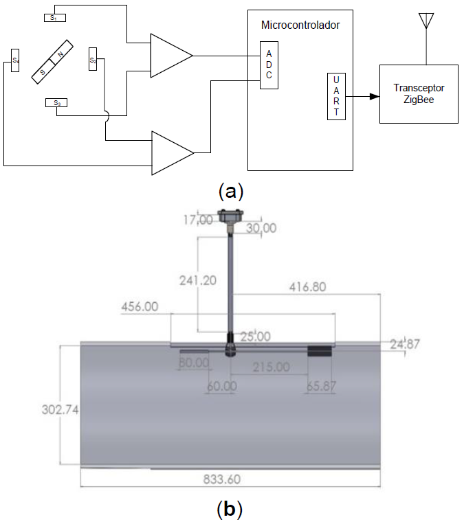
For the design of the liquid level measurement system, an array of four Hall A1324 (Allegro Microsystems) effect sensors was used. The sensors were placed in a circular arrangement spaced in quadrature, see figure 1a, in this way each sensor detects a magnetic field strength which depends on the relative orientation of the magnet coupled to the mechanical system of the float.

Fig. 1 Experimental arrangement of the measurement system for liquids. (a) Electronic system for conditioning and transmission of the signal via ZigBee protocol, (b) Coupling of the measuring system in the cylindrical container
For the signal conditioning, the differential voltage detected by each pair of sensors located 90 degrees apart was obtained. The scheme of the signal conditioning stage for the liquid level meter is shown below, as well as the simulated coupling in the cylindrical tank (Figure 1b).
The signal of the voltage conditioning amplifiers is applied to a PIC18F1320 microcontroller (Microchip Inc.) that digitizes the signal and executes the algorithm corresponding to the liquid level value adjustment function. A ZigBee Xbee ZB24 (Digi International) transceiver was used to display the information transfer.
2.2. Theoretical Calculations and System Calibration
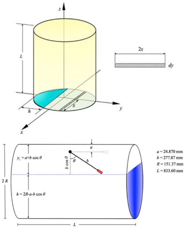
A system based on a cylinder with the dimensions shown in Figure 2b was used. The volume of a cylinder whose base is the semicircular region shown in Figure 2a is calculated. Where the differential volume element is given by the following expression (Eq. 1):

Fig. 2 Model used for theoretical calculation of volume. (a) Volume of a cylinder with semicircular base, (b) Actual approximation of the volume meter embedded in the cylindrical container
where
The voltage records to obtain the behavior of the float angle versus the voltage that the system emits, were carried out in triplicate. Its arithmetic mean and standard deviation of the readings were determined.
2.3 Data Analysis and Acquisition Software
The MPLABX development environment was used for the firmware implementation of the microcontroller responsible for the acquisition, and signal processing. For theoretical and experimental analysis, software tools such as SolidWorks v2018, Mathematica 10.0, Matlab R2015b and OriginLab v 8.0 were used.
3 Results and Discussion
For the determination of the volume contained in the cylinder as a function of the angle θ shown in Figure 2b, we note that:
Taking Eq. (5) and substituting in Eq. (4), the volume of the cylindrical container was obtained as a function of the angle (Eq. (6)). Where θ must be expressed in radians:
Experimentally, the angle was measured as a function of the voltage (ε). Table 1 summarizes the recorded readings, and where we can verify the angle and voltage correlation.
Table 1 Voltage readings recorded from the triplicate detection system. Abbreviations are as follows, θ: float angle, ε: measurement system voltage, μ: arithmetic mean, σ: standard deviation
| Θ | ε1 | ε2 | ε3 | μ | σ |
|---|---|---|---|---|---|
| 0 | 0.755 | 0.77 | 0.762 | 0.762 | 0.008 |
| 5 | 0.74 | 0.739 | 0.721 | 0.733 | 0.011 |
| 10 | 0.709 | 0.687 | 0.665 | 0.687 | 0.022 |
| 15 | 0.625 | 0.589 | 0.558 | 0.591 | 0.034 |
| 20 | 0.49 | 0.465 | 0.461 | 0.472 | 0.016 |
| 25 | 0.362 | 0.332 | 0.333 | 0.342 | 0.017 |
| 30 | 0.29 | 0.196 | 0.199 | 0.228 | 0.053 |
| 35 | 0.18 | 0.04 | 0.047 | 0.089 | 0.079 |
| 40 | -0.095 | -0.064 | -0.118 | -0.092 | 0.027 |
| 45 | -0.184 | -0.221 | -0.235 | -0.213 | 0.026 |
| 50 | -0.326 | -0.357 | -0.368 | -0.350 | 0.022 |
| 55 | -0.43 | -0.458 | -0.473 | -0.454 | 0.022 |
| 60 | -0.581 | -0.548 | -0.578 | -0.569 | 0.018 |
| 65 | -0.657 | -0.645 | -0.676 | -0.659 | 0.016 |
| 70 | -0.75 | -0.712 | -0.73 | -0.731 | 0.019 |
| 75 | -0.792 | -0.772 | -0.773 | -0.779 | 0.011 |
| 80 | -0.813 | -0.797 | -0.793 | -0.801 | 0.011 |
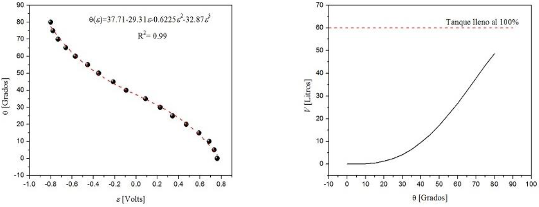
The behavior of the experimental measurements is shown in Figure 3a, where the spherical symbols represent the experimental data and the solid dotted line is an adjustment of a polynomial of order 3. The polynomial that best fitted this behavior was:

Fig. 3 Behavior of the readings and adjustment function found. (a) Adjust to a polynomial of order 3 for experimental angle data as a function of voltage, (b) Theoretical volume behavior as a function of angle
It is important to note that this last expression allows us to calculate the angle in degrees as a function of voltage. On the other hand, in Eq. (6) the angle in radians is required, therefore, Eq. (7) must be multiplied by a factor π/180.
Finally, substituting Eq. (7) in Eq. (6) we obtain the volume as a function of the voltage recorded by our remote system (Figure 3b).
In Figure 4, the printed circuits corresponding to the sensing stages (arrangement of the 4 Hall-effect sensors A1324 in the form of quadrature) and signal conditioning are observed.
4 Conclusions
In this paper, a liquid volume measurement system of a container was developed by monitoring the magnetic field strength to determine the position of a float. This system, unlike those based on variable resistance measurement, does not show loss of accuracy caused by transducer wear; and with respect to those that use ultrasonic sensor, errors in the measurement by reflection of ultrasonic beam in the walls of the tank are avoided when this is very narrow.
The electronic hardware is compact allowing its coupling to the mechanical system of the float arm, and together with the Zigbee transceiver, it allows to have a very complete measurement system with low energy consumption and compatible for integration as part of a variable measurement network.
On the other hand, the correlation of the angular position of the float arm with the contained volume was also determined. This correlation function can be applied to systems such as the one described above and when the dimensions of the cylindrical container and the length of the float arm are defined. The mathematical expression to determine the content volume can be implemented in the microcontroller firmware. Finally, this detection system can be coupled to different cylindrical tanks, as long as their dimensions for a, b, R and L are modified proportionally and in addition to their firmware update for these constants.


 nueva página del texto (beta)


