Introduction
The rise of 5G wireless standard boosts the interest for developing compliant transceivers, motivated by their appealing potential characteristics: increased electromagnetic compatibility, more reliability, more integration with other communication systems, wide bandwidths, low latency, among others (Kimery, 2017). Such features can be achieved by exploiting 4G legacy technology, particularly multi-antenna schemes, e.g. multiple-input multiple-output (MIMO) communications, beamforming arrays, space division multiple access (SDMA), and so on. However, the usage of multiple antennas on both sides of the channel implies the mandatory reduction of the electromagnetic mutual coupling among radiators and the measurement of several propagation-related parameters featured by the antennas. To maximize the capacity of the communications channel, each element of the array should receive a signal completely uncorrelated to the remaining signals arriving at the rest of the radiators. Thence, a metric to measure as straightforwardly as possible this phenomenon is needed.
A widespread metric found in the state-of-the-art to characterize the diversity performance of a pair of antennas is the Envelope Correlation Coefficient (ECC or ρ eij ). An adequate determination of the ECC is relevant to Research and Development (R&D) projects because it gives certainty about the behavior of a system of antennas, by establishing a measurable and a comparison point between prototypes. If the ECC is low, the proposed design is considered as “appropriate for MIMO applications”. Otherwise, mutual coupling reduction techniques become the kernel of the work, and their efficacy is proved by measuring the ECC before and after the implantation of the decoupling method. Thence, a novel mutual-coupling-reduction technique is publicized. Therefore, ECC and other multi-antenna parameters are fundamental to grant certainty to microwave and mm-wave related investigations.
However, the calculation and measurement of the ECC is a devious task. The so-called “exact method” or “far-field method” (Choi, 2019) needs the integration of the radiated electric field (
In the literature about RF and microwave theory and techniques, several alternatives have emerged to ease the computation of ECC, by simplifying Eq. (1) through many assumptions, some of them are not valid for every case. If simplified equations are applied to compute the ECC, inequitable comparisons between characterized prototypes may occur. As well, if two antenna models are characterized by using different ECC equations, which follow distinct assumptions, an inequitable confrontation could arise. In both cases, wrong conclusions may be drawn, and a methodological error could be made.
In this paper, an easy-to-program algorithm that allows computing the ECC by means of their simulated
State-of-the-art of calculation of the ECC
The correlation coefficients are used in the microwave and mm-wave literature to quantify the similarity of two communication channels (Chen, 2015a), by mathematically relating the incoming signals at the ports of a MIMO antenna (Ying, 2015). Mainly, three metrics are used to measure the correlation: power correlation coefficient, signal correlation coefficient, and envelope correlation coefficient (ECC) (Chen, 2015b; Rahmat, 2005). The latter is the most popular among antenna designers because it allows quantifying the orthogonality between radiation patterns of two antennas in the vicinity (Clauzier, 2015; Sharawi, 2017). The ECC decreases inversely proportional to the isolation among two ports, thence, if two nearby antennas are adequately decoupled, the ECC is expected to below (Wang, 2016). Recent literature considers ECC = 0.5 as an adequate limit for MIMO systems, in particular, for antenna arrays used on cellular telephony (Ying, 2015; Tsouslos, 2006).
The far-field radiation pattern method (Choi, 2019) to calculate the ECC utilizes the radiated field components from the i-th and j-th antenna following (1):
Where:
|
= complex vector function that describes the k-th 3D radiation pattern at the Fraunhofer zone |
〈,〉 = |
Hermitian product |
dΩ = |
the solid angle differential |
The integration over the complete sphere of the electric field radiated on the far-field region from the antennas, for all the frequencies over the whole operational bandwidth can be an expensive and cumbersome task since all values must be measured inside an appropriate facility. Several more cost-effective alternatives to compute the ECC has been developed in order to avoid this exact but devious method, as shown below.
For instance, (2) describes the same coefficient by applying the cross-polarization ratio (XPR), the components on θ and φ of the polarized electric field (Ek (Ω)), and the average power of the vertical P θ and horizontal P 𝜙 components (Andersen, 2003). However, its use is restricted to describe the performance of communication links in Rayleigh-fading channels (Ying, 2015).
Blanch, et al. (2003) derived (3), based on the scattering parameters of high-efficiency single-mode antenna systems. It does not require the measurement of the radiation pattern of the antennas under evaluation and it provides a clearer insight into the mutual coupling of two antenna ports. Its simplicity to evaluate over any given bandwidth induced its quick acceptance among the antenna designers.
However, some important drawbacks have been pointed out:
Equation (3) does not consider the total efficiency of the radiators, causing a strong deviation between the results obtained from it and from (1) when low-efficient radiators are evaluated (Sharawi, 2017). An expression that sets a lower limit or “guaranteed coefficient” was developed in (Hallbjorner, 2005), but large uncertainties are presented when the total efficiency is low, causing that the expression does not provide useful information for those cases.
Equation (3) can be only applied to lossless antennas, which is not the case for many applications. In (Li, 2013), a method based on the insertion of a shunt or series resistor, which represents the dielectric and conductor losses in the equivalent circuit of the antenna, was proposed. Simulations and measurements proved the high convergence of the technique compared to the far-field method, but its intricate procedure and difficulty to identify the appropriate equivalent circuit for every antenna complicate its application. Besides, it is only applicable for single-mode antennas that exhibit strong currents near the excitation port (Li, 2013).
An even more complex method using the cross-correlation Green’s function was elaborated in Antar (2015) and combined with the finite-difference time-domain method in (Srivastava, 2017), obtaining upstanding results, but at the expense of embroiling, even more, the calculation of the correlation coefficient. Recently, a method based on Spherical Near Field measurements was presented in (Cornelius, 2017), but its adoption has been not widely accepted till the date (Alieldin, 2018).
There is a direct trade-off between accuracy and complexity of the calculation method; moreover, the antenna array under study must meet the specified conditions which justify the simplifications of the ECC calculation, otherwise, the calculated value may lack physical sense.
State-of-the-art of computer-assisted calculation of ECC
ANSYS HFSS and CST Studio Suite are two widely accepted programs among investigators focused on R&D of microwave and mm-wave components and devices. Both applications can compute essential data involved in the design process of antennas, filters, transmission lines, and so on. Their solvers are based on the finite-element method (FEM) and the FDTD method, respectively. They can calculate relevant parameters, such as input impedance, the magnitude of radiated fields, attenuation, surface currents, among others. The most recent versions of both applications offer more specialized results obtained by post-processing, but they must be managed by the user after their solvers converge. Amidst these semiautomatic options, the calculation of multiport parameters is found.
HFSS contains a subroutine, referred to as “toolkit”, which returns the calculated ECC and diversity gain of a solved array of antennas but does not clarify the computing procedure (ANSYS, 2017). Such calculations must be performed for every frequency. Besides, this program does not offer any other alternative to compute the ECC.
On the opposite side, CST Studio Suite calculates by default the ECC between antennas using the scattering matrix method of (3) and offers a post-processing tool that calculates the coefficient using (2). Both methods of ECC evaluation can be performed over a frequency interval, without the necessity of setting monitors for each frequency, and their results are coincident if and only if three conditions are met:
The Gaussian distributions which describe the average power on vertical and horizontal components (P θ and P 𝜙 respectively) are equal (P θ = P 𝜙 = 1).
Cross-polarization radiation is zero (XPR = 0 dB).
The model under study is lossless (Computer Simulation Technology AG, 2010).
Both HFSS and CST offer the radiated E-field values of any simulated prototype in the Fraunhofer region, conveniently as real and imaginary parts over the θ and ϕ directions; however, on HFSS a Setup must be established for every frequency, or Discrete sweep must be performed, and a monitor must be set on CST per frequency of calculation. Therefore, if the interval of frequencies is extended, as in wideband and UWB antennas, the calculation time and required computational resources grow.
Mathematical derivation of the new method
The expression appearing in (Blanch, 2003) to determine the envelope correlation coefficient of two antennas by means of their radiated electric fields in the far-field region is shown in this paper as (1).
The Hermitian product of two different complex vector functions is calculated using Equation (5):
In which * denotes the complex conjugate function. It must be remarked that the squared modulus of a complex vector function can be expressed as a Hermitian product, as displayed in (6).
The Hermitian product of a function
Thence, (1) can be written in the more compact fashion of (8):
by defining B ij as (9):
Equation (9) can be used to represent the denominator of (8) by substituting i for j and vice versa. By defining the integration limits and substituting the differential dΩ=sinθ dθdϕ (9) can be rewritten as (10):
To apply the current method in a measurement or simulation process, (10) must be discretized since both simulated and measured electric fields radiated from an assembly of antennas are always a finite number of samples. For the most general case, closed-form expressions for the radiated field from an assembly of antennas are not always available; therefore, the integrations on (10) cannot be performed analytically. Following the procedure explained by Balanis (2001), section 2.7, a series approximation of (10) can be deduced as (11):
Where N uniform partitions of θ are obtained by means of (12):
Making the discreet variable θ n equals to:
Similarly, M uniform partitions of ϕ are obtained using (14):
Obtaining a discrete variable ϕ m :
By substituting (12-15) in (11), the approximation of B ij is given by:
Substituting (16) in (6) in terms of the electric fields, the Envelope Correlation Coefficient can be approximated by using (17):
Applying (3-5), the components of functions
Where:
The calculation method exposed here features more application generality than many of the procedures listed on the Introduction section, because it is not subject to radiation efficiency, total efficiency, port matching, and other characteristics of the antennas under test (AUT). This procedure establishes, directly the interaction of both radiated electric fields, instead of deducing it from the relations among other parameters, as other methods of calculation do (ANSYS, 2017) (Computer Simulation Technology AG, 2010).
Comparing results to commercial electromagnetic simulators
In order to prove the accuracy of the approximation made by Equations (18-19), a comparison of the results obtained by the presented numerical method, FDTD and FEM-solver solutions was performed. For demonstration purposes, two arrays consisting of two microstrip patch antennas were designed in HFSS 15 and CST Studio Suite 2016, on a Rogers RT/duroid 5880 substrate with thickness h = 1.27 mm, relative permittivity ε r = 2.2 and tan δ = 0.0004, as pictured on Figure 1, tuned to a center frequency of 2.45 GHz. Model “a” or “orthogonal” consists of two identical and independent patches placed perpendicularly one to each other, driven by a coplanar microstrip; model “b” or “copolar” places such patches collinear to each other, excited by means of an SMA connector. Microstrip patch antennas were selected since, as stated before, Eq. (3) is restricted to high-efficiency radiators, and this equation is going to be considered in the total analysis.
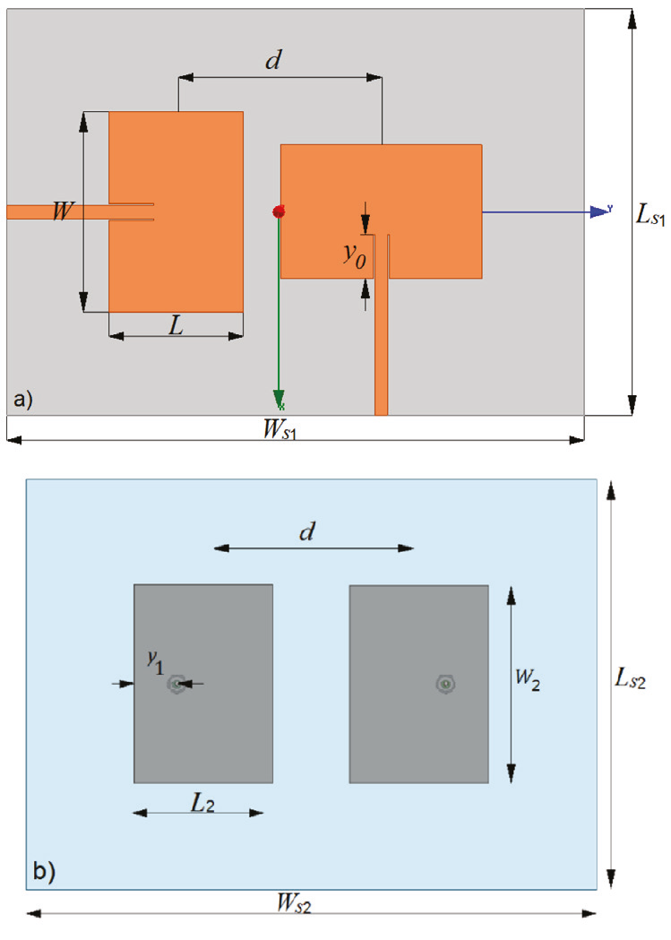
Figure 1 a) Model of orthogonal antennas and b) Model of collinear (copolar) antennas used along in this paper. Dimensions listed in Table 1
By using the classic microstrip patch antenna design and following the equations given in (Garg, 2001), the dimensions of the AUT were found and tuned by using the commercial electromagnetic simulation programs under test. Optimal dimensions are listed in Table 1, and the simulated S-parameters are shown in Figure 2. This figure also shows that the -10 dB impedance bandwidth of each element is approximately 30 MHz, from 2.43 to 2.46 GHz.
Table 1 Dimensions of antenna arrays pictured on Figure 1
| Dimension | Magnitude [mm] |
| d | 61.1825 |
| h | 1.27 |
| L1 | 40.1 |
| L 2 | 39.5 |
| L s1 | 101.2825 |
| L s2 | 118.22 |
| W 1 | 60.15 |
| W2 | 59.25 |
| Ws1 | 162.465 |
| Ws2 | 161.95 |
| y0 | 13.32 |
| y1 | 12.25 |
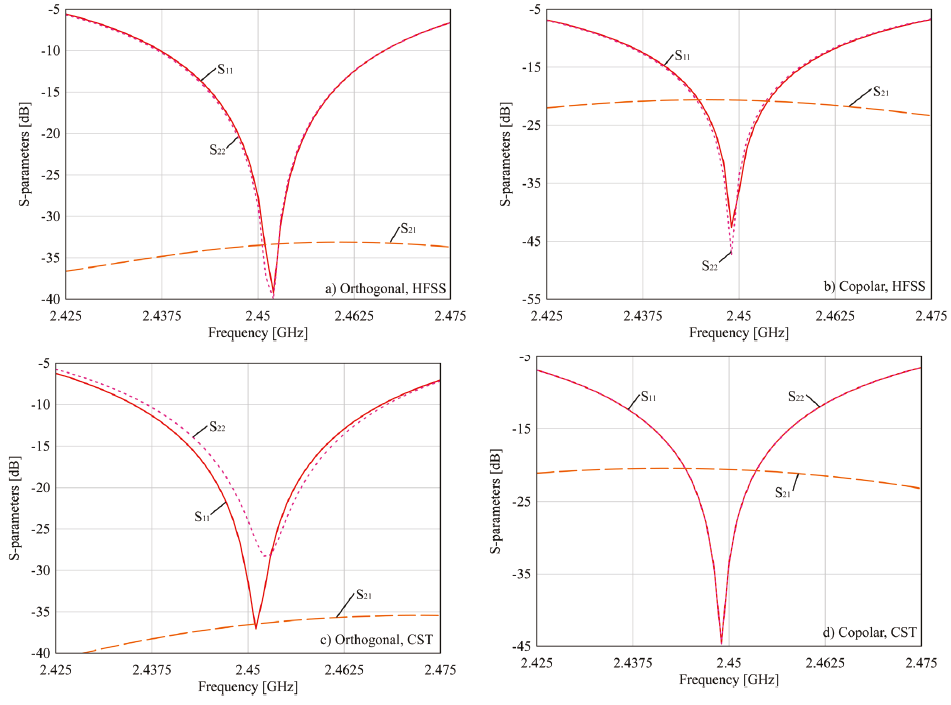
Figure 2 Magnitudes of the S parameters (in dB), calculated for the models “a” and “b” described on Figure 1, using HFSS and CST Studio Suite
In order to create comparable simulation conditions, the simulated results from both programs needed to be as similar as possible. This condition is almost accomplished for all parameters in both configurations, except for the S22 parameter, shown in Figure 2c, which magnitude diverges from that obtained with HFSS for the orthogonal configuration. To assure these results, every simulation on this paper was performed using a PC with 48 GB RAM, dual-core Intel Xeon processor with a 2.4 GHz internal clock. In HFSS, the convergence criterion (given by the parameter “Maximum Delta S”) was established on 0.015. In CST, the convergence criterion is influenced by the number of hexahedral cells per wavelength, established as 40, and is determined by the reflected wave “accuracy”, which was determined to be -40 dB. These conditions allowed obtaining an elevated similitude of the calculated S-parameters, as Figure 3 shows. This figure presents the high similarity of the real and imaginary parts of the scattering coefficients obtained from both EM simulators.
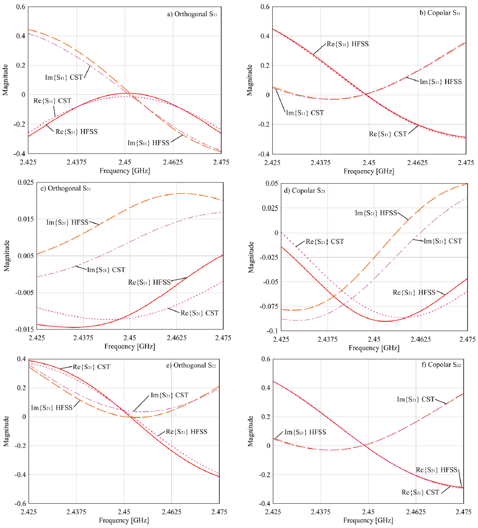
Figure 3 Comparison of the magnitudes of the real and imaginary parts of the scattering parameters for models orthogonal and copolar described on Figure 1, calculated by HFSS and CST Studio Suite
Figure 4 shows that the radiation efficiency and the total efficiency of the AUT, calculated by CST. These parameters exceed 80 % over their impedance bandwidth. Therefore, the use of Eq. (3) is also valid for these models.
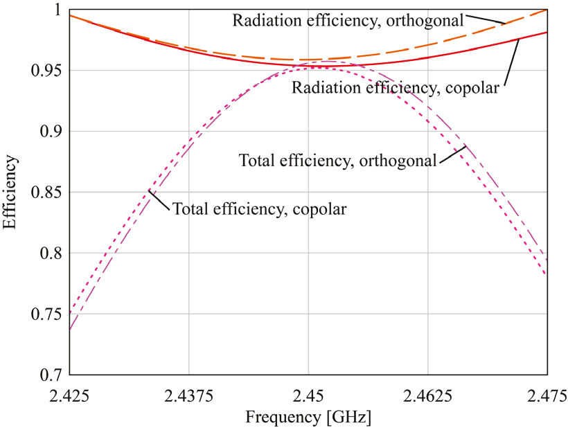
Figure 4 Radiation efficiency and total efficiency vs frequency of the antenna arrays depicted on Figure 1
For the purposes of this study, the spatial sampling step, over θ and ϕ coordinates, is called “angular resolution”. An angular resolution of 1 means that the spatial samples were registered every degree all over the infinite sphere, and so on.
Figure 5 shows the calculation of ECC every 1 MHz over the 2.425-2.475 GHz interval, obtained by the HFSS toolkit for both models of the AUT, using angular resolutions of 1°, 2°, 3°, 4°, 5°, 6° y 10°. As determined in recent literature, both arrays are acceptable to be used on MIMO communication, because the ECC values are considerably lesser than 0.5. Figure 5a, reveals that the ECC values for the orthogonal array exhibit more convergence than for the copolar array. A likely reason is that this is caused by the elevated mutual coupling between copolar patches, as S21 reveals in Figure 2. The trend shown in Figure 5 allows deducing that the accuracy of ECC calculation grows when the spatial sample size is reduced. However, the simulation time is increased, as Table 2 shows.
Table 2 Relation between angular resolution and simulation time exhibited by HFSS toolkit and CST post-processing tool, for orthogonal and copolar arrays
| Angular resolution [o] |
No. of samples |
HFSS Simulation time [s] |
CST Simulation time [s] |
||
| Orthogonal array |
Copolar array |
Orthogonal array |
Copolar array |
||
| 1 | 64800 | 1887 | 2015 | 886 | 910 |
| 2 | 32400 | 455 | 478 | 268 | 306 |
| 3 | 7200 | 205 | 218 | 160 | 186 |
| 4 | 4050 | 129 | 133 | 115 | 124 |
| 5 | 2592 | 83 | 86 | 97 | 110 |
| 6 | 1800 | 62 | 66 | 85 | 86 |
| 10 | 648 | 30 | 33 | 65 | 69 |
The results of applying the post-processing tool of CST to compute ECC, considering P θ = P 𝜙 = 1 and XPR = 0 dB, are shown in Figure 6, which induces to conclude that this method is not sensible to the angular resolution. By examining Table 2, it is shown that HFSS doubles the simulation time of CST for similar conditions.
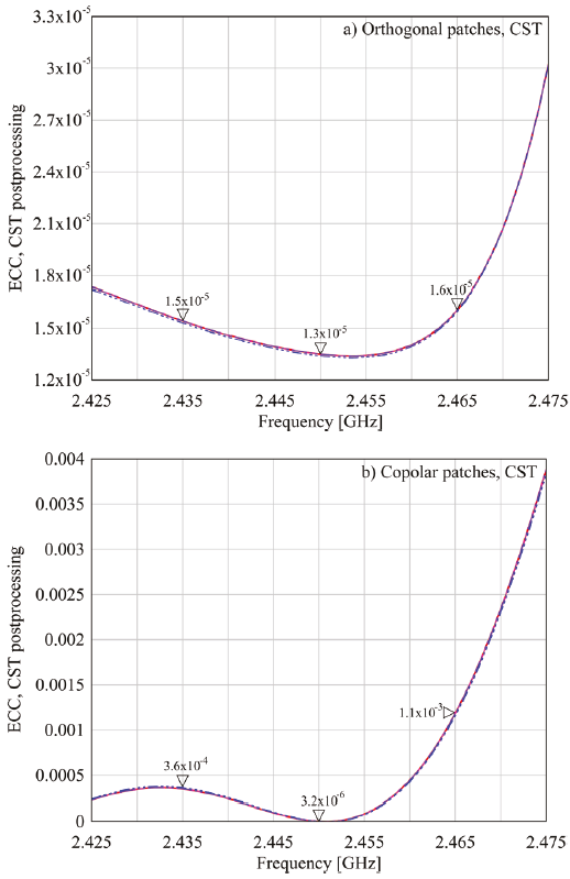
Figure 6 ECC curves calculated for a) Orthogonal and b) Copolar models by means of the CST post-processing tool
The complex-valued electric fields on the Fraunhofer region for both models were obtained by means of HFSS and CST, and (18-19) were applied to obtain the ECC. The proposed method was programmed on C language, due to its high efficiency on the dynamic memory allocation, compared to Matlab or Python. The algorithm is described on Appendix A. For each angular resolution, the
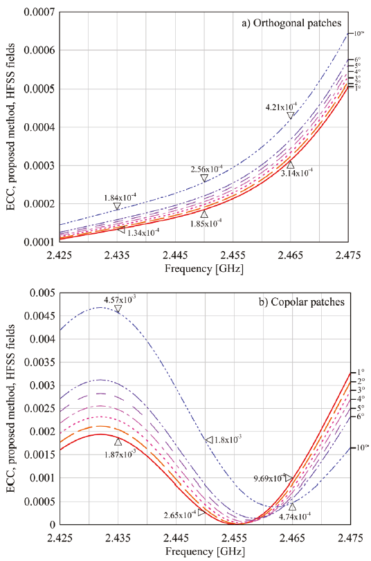
Figure 7 Calculated ECC values depending on the angular resolution, using (18-19) and HFSS for the a) Orthogonal and the b) Copolar models
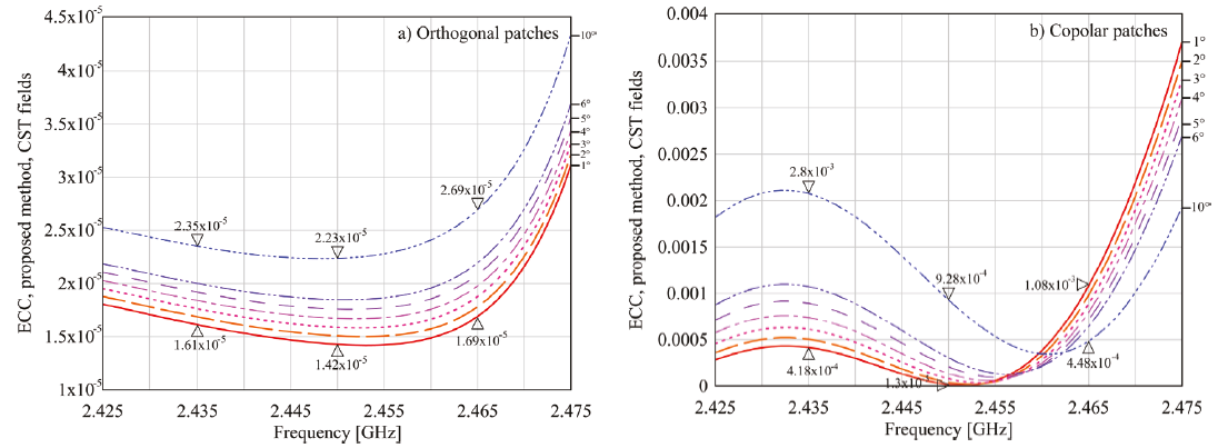
Figure 8 Calculated ECC values depending on the angular resolution, using (18-19), and CST for the a) Orthogonal and the b) Copolar models
As observed in Figures 7 and 8, the angular resolution has more impact on the performance of the proposed method when using the
As Table 2 reveals, HFSS exhibits the largest simulation time, which doubles CST calculation time for the angular resolution of 1°. On the other hand, the proposed method shows little sensibility to the geometry of the AUT, unlike is observed on commercial solvers. Moreover, as seen by comparing the results displayed in Table 2 and Table 3, the proposed algorithm is between 39 and 49 times faster than the HFSS toolkit, and 12 to 13 times compared to CST postprocessing tool on the calculation time. It is remarked that the simulation time of the proposed procedure becomes more competitive to CST post-processing tool as the spatial step is enlarged: for an angular resolution of 4°, the proposed algorithm is 27 times faster than CST semiautomatic tool, but when the resolution is changed to 10°, the proposed algorithm gets the ECC results 77 times faster than CST.
Table 3 Relation between angular resolution and simulation time exhibited by the proposed method
| Angular resolution [o] |
Proposed method, HFSS fields, 1°, orthogonal [s] |
Proposed method, HFSS fields, 1°, copolar [s] |
Proposed method, CST fields, 1°, orthogonal [s] |
Proposed method, CST fields, 1°, copolar [s] |
| 1 | 52.89 | 51.55 | 69 | 68.52 |
| 2 | 13.11 | 12.67 | 23 | 17.32 |
| 3 | 5.965 | 5.753 | 8 | 7.863 |
| 4 | 3.577 | 3.271 | 4.606 | 4.568 |
| 5 | 2.266 | 2.236 | 3.092 | 3.053 |
| 6 | 1.562 | 1.58 | 2.214 | 2.197 |
| 10 | 0.7137 | 0.6653 | 0.921 | 0.895 |
The comparison of applying the proposed algorithm, HFSS, and CST post-processing tools, and the S-parameters method described by Eq. (3), is found in Figure 9. It is revealed that the algorithm calculates very similar values to the commercial semiautomatic tools when their respective computed
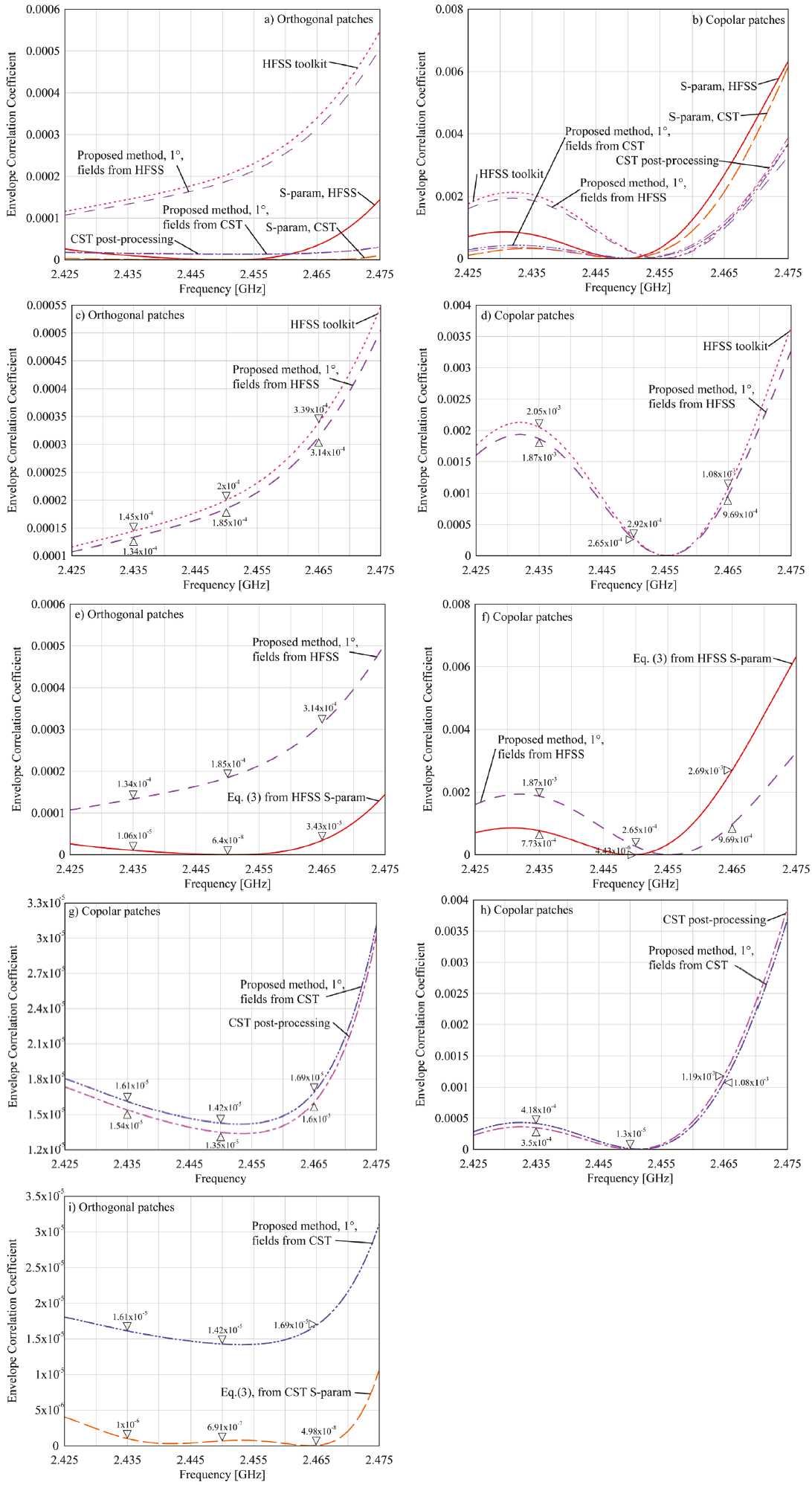
Figure 9 Comparison of ECC calculations from different equations and solvers. a) Comparison of all the available methods for the orthogonal patches, b) Comparison of all the available methods for the copolar patches, c) Proposed method vs HFSS toolkit on the orthogonal patches, d) Proposed method vs HFSS toolkit on the copolar patches, e) Proposed method vs (3) from HFSS on orthogonal patches, f) Proposed method vs (3) from HFSS on copolar patches, g) Proposed method vs CST post-processing tool on the orthogonal patches, h) Proposed method vs. CST post-processing tool on the copolar patches, i) Proposed method vs (3) from CST on orthogonal patches, j) Proposed method vs (3) from CST on copolar patches
Conclusions
In this paper, an easy to program accurate algorithm to compute the Envelope Correlation Coefficient from the computed radiated electric fields on the Fraunhofer region is proposed. The novel procedure is applied to a study case, obtaining the ECC values up to 77 times faster than the commercial software tools without losing any accuracy. The developed algorithm was compared to two of the most used electromagnetic simulator software, and the computing time of the ECC is greatly enhanced by several magnitudes. On the other hand, it is demonstrated that this process does not need special care regarding cross-polarization levels, radiation efficiency, or any other factor that can increase the complexity of the calculation of the metric. All these algorithm features are obtained without compromising the exactness of the results. The relative error of the method compared to the other two ones, changed from some percent units when the angular resolution was set to the smallest value, close to 1°, and tends to increase to some percent tens as the angular resolution rises. For example, for HFSS goes from 3 % to 39 % at the center frequency when the angular resolution changes from 2° to 10°, respectively. For CST, considering the same case, the error changes from 6 % to 57 %, taking the same angular resolution.
This procedure is proposed to ease the computation of ECC, for the sake of reducing certain methodological errors indicated in this work.


 nueva página del texto (beta)


