SciELO - Scientific Electronic Library Online

 
vol.59 número1Photometric Observations of Minor Planets with the Tonantzintla Schmidt Camera I. Light curve Analysis of Main-Belt and Near-Earth AsteroidsSome Predictions of Scaling Relations: The Case of the Black Hole in M87 índice de autoresíndice de materiabúsqueda de artículos
Home Pagelista alfabética de revistas  

Servicios Personalizados

Revista

Articulo

Indicadores

Links relacionados

  • No hay artículos similaresSimilares en SciELO

Compartir


Revista mexicana de astronomía y astrofísica

versión impresa ISSN 0185-1101

Rev. mex. astron. astrofis vol.59 no.1 Ciudad de México abr. 2023  Epub 21-Oct-2024

https://doi.org/10.22201/ia.01851101p.2023.59.01.05 

Articles

Numerical Investigations of the Orbital Dynamics Around a Synchronous Binary System of Asteroids

L. B. T. Santos1 

Allan Kardec de Almeida Jr1  2 

P. A. Sousa Silva3 

M. O. Terra4 

D. M. Sanchez5 

S. Aljbaae1 

A. F. B. A. Prado6  7 

F. Monteiro8 

1 Division of Space Mechanics and Control. National Institute for Space Research, INPE. São José dos Campos, Brazil.

2 Instituto de Telecomunicações, Portugal.

3 São Paulo State University, UNESP, Brazil.

4 Technological Institute of Aeronautics, ITA. São José dos Campos, Brazil.

5 The University of Oklahoma, Norman OK, USA.

6 Postgraduate Division - National Institute for Space Research (INPE), São Paulo, Brazil.

7 Professor, Academy of Engineering, RUDN University, Moscow, Russia.

8 National Observatory, ON. Rio de Janeiro, Brazil.


ABSTRACT

In this article, equilibrium points and families of periodic orbits in the vicinity of the collinear equilibrium points of a binary asteroid system are investigated with respect to the angular velocity of the secondary body, the mass ratio of the system and the size of the secondary. We assume that the gravitational fields of the bodies are modeled considering the primary as a mass point and the secondary as a rotating mass dipole. This model allows to compute families of planar and halo periodic orbits that emanate from the equilibrium points L 1 and L2. The stability and bifurcations of these families are analyzed and the results are compared with the results obtained with the restricted three-body problem (RTBP). The results provide an overview of the dynamical behavior in the vicinity of a binary asteroid system.

Key Words: celestial mechanics — minor planets; asteroids; general

RESUMEN

En este artículo, se investigan los puntos de equilibrio y las familias de ´orbitas periódicas en la vecindad de los puntos de equilibrio colineal de un sistema binario de asteroides con respecto a la velocidad angular del cuerpo secundario, la relación de masa del sistema y el tamaño del secundario. Suponemos que los campos gravitatorios de los cuerpos se modelan asumiendo el primario como punto masa y el secundario como dipolo de masa giratorio. Este modelo permite calcular familias de ´orbitas planas y periódicas de halo que emanan de los puntos de equilibrio L 1 y L2. Se analiza la estabilidad y bifurcaciones de estas familias y se comparan los resultados con los obtenidos con el problema de los tres cuerpos restringido (RTBP). Los resultados brindan una descripción general del comportamiento dinámico en la vecindad de un sistema binario de asteroides.

1 Introduction

In recent years, the investigation and analysis of small celestial bodies have become fundamental to deep space exploration. Thus, understanding the dynamical behavior in the vicinity of small bodies is of great interest for the design of exploration missions and also for planetary science.

However, describing how a particle behaves around these objects is a challenging subject in astrodynamics, mainly due to the combination of the rapid rotation of the asteroids around their axis together with the non-spherical shapes.

In particular, an increasing number of binary asteroid systems has been observed throughout the Solar System and, in particular, among the near-Earth asteroids (NEAs). It is estimated that about 15% of NEAs larger than 0.3 km are binary systems Pravec et al.(2006), Margot et al.(2015). Most of these binaries are formed by a more massive primary component, usually with a nearly spherical shape, and a small secondary component, generally referred to as satellite Pravec et al.(2006), Pravec & Harris(2007), Walsh et al.(2008), Zhang et al.(2020).

There are several types of binary asteroid systems, which have been grouped according to their physical properties (e.g. size, rotation, mass ratio, diameter; Pravec & Harris 2007). The characteristics of these groups also suggest different formation mechanisms. As shown by Pravec & Harris(2007), the Type A binary asteroids are composed of small NEAs, Mars crossers (MC), and Main-Belt Asteroids (MBA), with primary components less than 10 km in diameter and with a component size ratio (Ds/Dp) less than 0.6. The Type B, in turn, consists of small asteroids with nearly equal size components (Ds/Dp>0.7) and with primary diameters smaller than 20 km. The Types L and W are, respectively, composed of large asteroids (D>20 km) with relatively very small component size ratio (Ds/Dp<0.2) and of small asteroids (D<20 km) with relatively small satellites (Ds/Dp<0.7) in wide mutual orbits.

Most Type A binary asteroids are synchronous systems, that is, the rotation period of the secondary component is equal to the orbital period around the center of mass of the system Pravec et al.(2006), Pravec et al.(2016). Numerical simulations revealed that binary systems are likely to undergo a chaotic process of energy dissipation involving tidal forces that allows the system to evolve to a fully synchronous end state Jacobson & Scheeres(2011). According to Jacobson & Scheeres(2011), the higher the mass ratio of the binary system, the faster the synchronization can be achieved. This happens because each member of the system exerts tidal forces with the same proportion over each other. Thus, as most systems have mass ratios less than 0.5, we find in the literature a larger number of systems with only the secondary component coupled with the orbital movement Pravec et al.(2016).

Performing semi-analytical and/or numerical investigations of the orbits and equilibrium solutions around asteroid systems using simplified models can be useful to provide some preliminary understanding of such systems Werner(1994), Liu et al.(2011). Simplified models can be used to approximate the gravitational field of irregularly shaped bodies, requiring less computational effort and generating considerable results in a short period of time. Another advantage of using a simplified model is that we can easily investigate the effects of a given parameter on the dynamics of a spacecraft around asteroids, such as, the distribution of stable periodic orbits Lan et al.(2017), the stability of the equilibrium points Zeng et al.(2015), Barbosa Torres dos Santos et al.(2017), as well as the permissible parking regions Yang et al.(2015), Zeng et al.(2016). In addition, simplified models can be used to support the orbit design Wang et al.(2017) and feedback control Yang et al.(2017).

Due to their advantage and considerable results, several simplified models have been proposed to study the orbital dynamics of a particle in the vicinity of irregular bodies. For example, Riaguas et al.(1999), Riaguas et al.(2001) analyzed the dynamics of a particle under the gravitational force of an asteroid modeled as a straight segment. Zeng et al.(2016) analyzed the influence of the parameters k (angular velocity) and μ (mass ratio) on the equilibrium solutions using the rotating mass dipole model and observed that there are always 5 equilibrium points when considering the primary bodies as points of mass. Other works have investigated the dynamics around small irregular bodies using a simplified model given by an homogeneous cube Liu et al.(2011), a simple flat plate Blesa.(2006), a rotating mass dipole Zeng et al.(2015), Barbosa Torres dos Santos et al.(2017)), dos Santos et al.(2017), the dipole segment model Zeng et al.(2018), a rotating mass tripole Lan et al.(2017), dos Santos et al.(2020), Santos et al.(2021), and many others.

In particular, aiming to understand the dynamical environment in the vicinity of irregular bodies, Aljbaae et al.(2020) investigated the dynamics of a spacecraft around the asynchronous equal-mass binary asteroid (90) Antiope; the authors applied the Mascon gravity framework using the shaped polyhedral source Chanut et al.(2015), Aljbaae et al.(2017) to consider the perturbation due to the polyhedral shape of the components. The perturbations of the solar radiation pressure at the perihelion and aphelion distances of the asteroid from the Sun were also considered in that study. In order to investigate the stability of periodic orbits, Chappaz Howell(2015) considered the asynchronous binary asteroid system using the triaxial ellipsoid model and observed that the non-spherical shape of the secondary body significantly influences the behavior of the halo orbit around L 1 and L 2 .

As said before, simplified models are useful to provide some preliminary understanding of the motion around binary systems, and the circular restricted three-body problem is suitable and often used to investigate the dynamics around small bodies de Almeida Junior Prado (2022). Furthermore, even landing trajectories have been evaluated using a spherical shape for the gravitational field of the primaries in the circular restricted three-body problem Tardivel Scheeres (2013), Celik Sanchez (2017), Ferrari et al. (2016). Although the orbit-attitude coupled equations of motion for a binary asteroid can be obtained using a more sophisticated model, which takes into consideration a potential for a non-spherical distribution of mass Scheeres et al.(2021), Wen Zeng (2022), they are only essential for very close encounters, such as for landing approaches. In this study, the dynamics is investigated for orbits around the binary system of asteroids. Thus, in this contribution, a more simplified model is used, whose results capture the essential parts of the physics of the problem, although its accuracy depends on the parameters of the specific mission. Therefore, we carry out a numerical investigation using the simplified model called a Restricted Synchronous Three-Body Problem, as introduced by Barbosa Torres dos Santos (2017). The practical advantage of using this model is that we can, in a relatively simple way, analyze the influence of the dimension of the secondary body on the dynamics of a spacecraft in the neighborhood of M 2.

We focus on the behavior of a particle of negligible mass in the vicinity of a binary system of Type A (NEAs and MBAs). The reason for choosing this class of asteroids is that the NEAs, in particular, are asteroids that pass near the Earth and most of the systems that are part of this class are synchronous systems. Our aim is to understand how the parameters of the dipole, the dimension (d) and the mass ratio (μ*) of the system, influence the stability, period and bifurcation of the periodic orbits around the equilibrium points. In § 2 we provide the equation of motion of the three-body synchronous restricted problem. In § 3, we investigate the influence of the force ratio (k) on the appearance of the equilibrium points, keeping the values of μ* and d fixed. Then, in § 4, we investigate the influence of μ* and d on periodic orbits (planar and halo) around the equilibrium points L 1 and L 2, considering k fixed (k = 1). Finally, in § 5, we provide the final considerations that were obtained in this article.

2 Equations of motion

Consider that the motion of a particle with negligible mass, P(x, y, z), is dominated by the gravitational forces of the primary bodies M 1 and M 2. As already mentioned, the distance between M 1 and M 2 is assumed to be D = 12 km, which will be the normalization factor in the rest of this work. The larger primary is considered to be a point mass with mass m 1 and the secondary is modeled as a rotating mass dipole formed by m 21 and m 22, as shown in Figure 1.

Figure 1: Representative image of the geometric shape of the system considered (not in scale). 

In canonical units, the sum of the masses of the bodies M 1 and M 2 is unitary. In this work, for all numerical simulations, we assume that m1>m21=m22 and that the mass ratio is defined by μ*=m21/(m1+m21+m22). By analogy, μ*=μ/2, with μ being the usual mass ratio used in the classical restricted three-body problem.

The angular velocity, given by ω = ωz, is aligned with the z-axis of the system. Here, the unit of time is defined such that the orbital period of the primary bodies around the center of mass of the system is equal to ω-1. Because the system is synchronous, the orbital period of M 2 around the center of mass is the same as its orbital period around the axis of the dipole.

With respect to the barycentric rotating frame, the masses m 1, m 21 and m 22 are fixed along the x-axis with coordinates x1=-2μ*, x21=-2μ*-d2+1 and x22=-2μ*+d2+1, respectively, where d, given in canonical units, is the distance between m 21 and m 22.

Using the generalized potential

Ω=x2+y22+k1-2μ*r1+μ*r21+μ*r22, (1)

we can write the equations of motion of P in a rotating frame centered on the barycenter of the system (M 1- M 2) as follows:

x˙y˙z˙x¨y¨z¨=x˙y˙z˙2y˙+DxΩ-2x˙+DyΩDzΩ, (2)

with

r1=(x-x1)2+y2+z2,r21=(x-x21)2+y2+z2,r22=(x-x22)2+y2+z2,

where DxΩ denotes the partial derivative of Ω with respect to x and the same notation is used for y and z. The dimensionless parameter k represents the ratio between gravitational and centrifugal accelerations, k=G(M)/(ω*2D3), where M is the total mass of the system in kg, ω* is the angular velocity of the M 2 in rad/s, D is the distance, in meters, between M 1 and the center of mass of M 2 and, finally, G = 6.67408×10⁻¹¹m3kg-1s-2 Zeng et al.(2015), Feng et al.(2016).

The free parameters of the system are d, μ* and k, which correspond, respectively, to the size of M 2, the mass ratio and a parameter accounting for the rotation of the asteroid. When k is equal to 1, the bodies orbit the center of mass of the system without any internal forces in the dipole. On the other hand, when k < 1, the dipole is stretching, while it is compressing when k > 1. Therefore, depending on the class of the binary system being analyzed, we need to consider the force ratio value (k). A particular case occurs when d (distance from the mass dipole) is equal to zero, causing the bodies of mass m 21 and m 22 to overlap, becoming a point of mass, with mass ratio 2 μ*. The classical Restricted Three-Body Problem corresponds to the particular case d = 0 and k = 1 McCuskey(1963), Szebehely(1967). Also, when d 0 and k = 1, we have the Restricted Synchronous Three-Body Problem Barbosa Torres dos Santos et al.(2017).

2.1 Equilibrium Point and Stability Analysis

Let x=(x, y, z, x˙, y˙, z˙) R6 be the state vector of a massless particle and f:R6  R6 be

f(x)=f1f2f3f4f5f6=x˙y˙z˙2y˙+DxΩ-2x˙+DyΩDzΩ. (3)

The equilibrium points L i , i = 1,2,3,4,5 are defined as the zeros of f(x). To determine the linear stability of each equilibrium, one needs to translate the origin to the position of this equilibrium point and linearize the equations of motions around this point. Thus, the linearization over any of these equilibrium points is

x˙=DLix, (4)

where DLi is the derivative of f(x) computed at the equilibrium point L i .

To determine the linear stability of the equilibrium points (L i , i = 1,2,3,4 and 5), it is necessary to transfer the origin of the coordinate system to the position of the equilibrium points (x0,y0,z0) and then to linearize the equations of motion around these points, obtaining the results shown below.

ξ¨-2η˙=Ωxx(x0,y0,z0)ξ+Ωxy(x0,y0,z0)η+Ωxz(x0,y0,z0)ζ , (5)

η¨+2ξ˙=Ωyx(x0,y0,z0)ξ+Ωyy(x0,y0,z0)η+Ωyz(x0,y0,z0)ζ , (6)

ζ¨=Ωzx(x0,y0,z0)ξ+Ωzy(x0,y0,z0)η+Ωzz(x0,y0,z0)ζ , (7)

where the partial derivatives in (x0,y0,z0) mean that the value is calculated at the equilibrium point being analyzed. Partial derivatives are shown in equations 8 - 13.

Ωxx=1+k.3(1-2μ*)(x-x1)2((x-x1)2+y2+z2)5/2-1-2μ*((x-x1)2+y2+z2)3/2)+3μ*(x-x21)2((x-x21)2+y2+z2)5/2-μ*((x-x21)2+y2+z2)3/2-3μ*(x-x22)2((x-x22)2+y2+z2)5/2+μ*((x-x22)2+y2+z2)3/2., (8)

Ωyy=1+k.3(1-2μ*)y2((x-x1)2+y2+z2)5/2-1-2μ*((x-x1)2+y2+z2)3/2+3μ*y2((x-x21)2+y2+z2)5/2-μ*((x-x21)2+y2+z2)3/2+3μ*y2((x-x22)2+y2+z2)5/2-μ*((x-x22)2+y2+z2)3/2., (9)

Ωzz=k.3(1-2μ*)z2((x-x1)2+y2+z2)5/2-1-2μ*((x-x1)2+y2+z2)3/2+3μ*z2((x-x21)2+y2+z2)5/2-μ*((x-x21)2+y2+z2)3/2+3μ*z2((x-x22)2+y2+z2)5/2-μ*((x-x22)2+y2+z2)3/2., (10)

Ωxy=Ωyx=k.3(1-2μ*)(x-x1)2y((x-x1)2+y2)5/2+3μ*(x-x21)2)y((x-x21)2+y2)5/2+3μ*(x-x22)y((x-x22)2+y2)5/2., (11)

Ωxz=Ωzx=k.3(1-2μ*)(x-x1)z((x-x1)2+y2+z2)5/2+3μ*(x-x21)z((x-x21)2+y2+z2)5/2+3μ*(x-x22)z((x-x22)2+y2+z2)5/2., (12)

Ωyz=Ωzy=k.3(1-2μ*)yz((x-x1)2+y2+z2)5/2+3μ*yz((x-x21)2+y2+z2)5/2+3μ*yz((x-x22)2+y2+z2)5/2.. (13)

In equations 5 - 7, ξ, η and ζ represent the position of the particle with respect to the equilibrium point. Through numerical analysis, we observed that the equilibrium points exist only in the xy plane, regardless of the values assigned to d, μ* and k. Due to the fact that the equilibrium points for the rotating mass dipole model are in the xy plane, the equation 7 is decoupled (it does not depend on ξ and η); therefore, the equation of motion 7 becomes

ζ¨=-ϑζ, (14)

where ϑ is constant and depends on the values assigned to d, μ* and k. Equation 14 shows that the motion perpendicular to the xy plane is periodic with frequency ω = ϑ. Motion in the z direction is therefore limited with

ζ=c3cos(ϑt)+c4sin(ϑ)t, (15)

where c3 and c4 are integration constants.

When the motion is in the xy plane, the non-trivial characteristic roots of the equations 5, 6 were obtained in Barbosa Torres dos Santos et al.(2017) (considering k = 1.). The linearization around L1 and L2 provides a pair of real eigenvalues (saddle), corresponding to one-dimensional stable and unstable manifolds, and one pair of imaginary eigenvalues, suggesting a two-dimensional central subspace in the plane xy, which accounts for an oscillatory behavior around the equilibrium point of the linear system Howell(1982), Haapala et al.(2015). Hence, in general, for L1 and L2, the stability type is saddle×center×center for the problem studied here and also for the CRTPB considering 0 < μ 0.5. The Lyapunov Center Theorem guarantees, for the planar case, the existence of a one-parameter family of periodic orbits emanating from each of the collinear equilibrium points. Thus, for the spatial case, two one-parameter families of periodic orbits around L1 and L2 are expected. It was observed that the nature of the eigenvalues of the collinear equilibrium points is not altered when we vary d, μ* and k.

Consider the linearized dynamics around the L1 equilibrium point. We will adopt the coordinates x'=(ξ; η; u; v), where u and v are the velocities in the x and y direction, respectively, for the physical variables in the linearized planar system. To differentiate, we will use the coordinates x0=(x;y;x˙;y˙) for the physical variables in the nonlinear system and, finally, y = (y1; y2; y3; y4) for the variables in the diagonalized system. We know that if we choose an initial condition anywhere near the equilibrium point the real components of the eigenvalues (stable and unstable) will dominate the particle’s behavior. But instead of specifying any initial condition for the system, we want to find an orbit around the equilibrium point L1, for example, with some desired behavior, such as a periodic orbit. This becomes easy if we use the diagonalized system (y0) to determine the initial conditions. As we want to minimize the component in the unstable direction of the non-linear path, we must choose the initial conditions that correspond to the harmonic motion of the linear system. Thus, we choose the initial condition in the diagonalized system as y0 = (0; 0; y3; y4), where the non-zero initial values can be complex numbers and are intended to amplify the oscillatory terms. Null terms have the function of nullifying exponential (unstable) terms. In fact, if we want to get real solutions at the x' coordinates, we must consider y3 and y4 as complex conjugates. Transforming these conditions back to the original coordinates of the linear system, from the transformation x0 = Ty0, we find the initial conditions in the linearized system x'0 = (x', y', u, v), where T is the matrix of the eigenvectors of the state transition matrix A. The Jacobian matrix A contains the Hessian pseudo potential derived from the truncated Taylor series expansion over the reference solution.

Due to the fact that these initial conditions were chosen to nullify the unstable and stable eigenvectors, they provide a harmonic movement in the linear system.

Now that we have the initial conditions for the linear system, we want to find a periodic planar orbit in the nonlinear system.

We note that the potential function for the system studied here depends only on the distances that a spacecraft are from the primary bodies, that is, it has symmetry with respect to the x-axis. Taking advantage of the fact that the planar orbits are symmetrical with respect to the x -axis, the initial state vector takes the form x0 = x0 0, 0, y˙0 T. These symmetries were used to find symmetric periodic orbits. This was done by determining the initial conditions, on the x-axis, where the initial velocity is perpendicular to this axis (y˙) and then the integration is done until the path returns by crossing the x-axis with the speed orientation y˙f opposite to the initial condition. This orbit can be used as an initial guess to use Newton’s method, where the target state is quoted above; that is, that the orbit returns to x-axis with normal velocity. The equations of motion and the state transition matrix are incorporated numerically until the trajectory crosses the x-axis again. The final desired condition has the following form: xf = xf 0, 0, y˙f T.

3 Collinear equilibrium points as a function of the ratio between gravitational and centrifugal accelerations

In this section, we analyze the influence of the parameter k on the position of the collinear equilibrium points, since the influence of d and μ* on the collinear points has already been performed in the work of Barbosa Torres dos Santos et al. (2017).

To determine how k affects the positions of the collinear equilibrium points, we consider μ* = 1×10⁻³ and d = 1/12 canonical units.

Figure 2 shows the x coordinates of L1, L2 and L3 as a function of k. Because they are at both ends of the x axis, the positions of L2 (right curve) and L3 (left curve) are more affected than the position of L1. Consider that there are three forces acting on the system: (i) the gravitational force of M1; (ii) the gravitational attraction of M2; and (iii) the centrifugal force, which is directly proportional to the angular velocity of the system around the center of mass and the distance between the equilibrium point and the center of mass of the system. Thus, by decreasing the angular velocity of the asteroid system around the center of mass, as k becomes larger, it is necessary to increase the distance between P and the center of mass, such that the centrifugal force remains at the same value and it counterbalances the gravitational forces from M1 and M2, which remain unchanged. Thus, L2 and L3 move away from the center of mass of the system. Although L1 also moves away from the center of mass of the system, it does so in a more subtle way. This is because, when moving away from the center of mass of the system, L1 approaches M2. Regarding the gravitational force increases, a balancing force is needed to prevent L1 from going too close to M2.
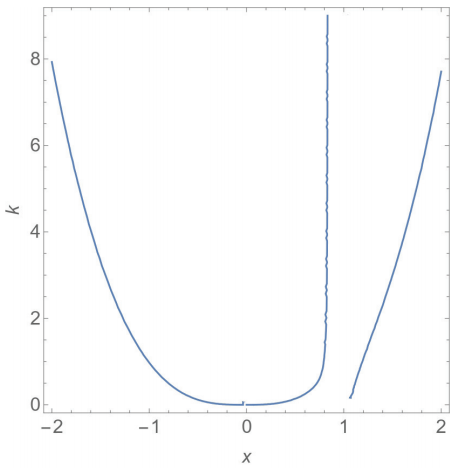
Figure 2: x-coordinates of the equilibrium points L1, L2 and L3 for different values of k. The color figure can be viewed online. 

As shown in Figure 2, the x coordinates of L2 and L3 tend to ± , respectively, when k  , that is, when the asteroid system ceases to rotate. This implies that L2 and L3 cease to exist when the asteroids are static. On the other hand, the equilibrium point L3 continues to exist when k  , due to the balance between the gravitational forces between M1 and M2.

4 Periodic orbits around the first and second collinear equilibrium points as a function of the mass parameter and the size of the dipole

Based on previous knowledge about Type A asteroids, we consider that the most massive primary is spherical in shape and with a diameter of 5 km Pravec Harris(2007), Walsh Jacobson(2015). Also, knowing that, on average, the mutual orbit of type A binary asteroids has a semi-major axis of about 4.8 primary component radii Walsh & Jacobson(2015), we consider that the distance between the bodies is 12 km, which is the normalization factor for the distances. Finally, type A asteroids are known to have moderately sized secondaries, ranging from 4% to 58% of the size of the primary; the mass ratios m2/(m1+m2) vary from 6.4×10⁻⁵ to 2.0×10⁻¹. Based on this evidence, we will consider in this analysis the dimension of the secondary from 0 to 2 km, where we vary it in steps of 500 meters, and a range of the mass ratios from 1×10⁻⁵ to 1×10⁻¹, where we vary them in steps of 10-1.

Periodic orbits are of special interest to explore the dynamical behavior of a massless particle in the vicinity of two primary bodies.

The results below were obtained by calculating approximately 3500 orbits from each family, starting from an initial condition with very low amplitude, and continuing the families until the orbits obtained came near the surface of the asteroids. To find symmetric periodic orbits, we consider k = 1, that is, the bodies orbit the center of mass of the system without any internal forces.

Each family was calculated for different values of μ* and d to highlight the effect of the mass ratio of the system and of the elongated shape of the secondary body on the dynamical behavior of a space vehicle in the vicinity of the binary system. To analyze the influence of the elongation of the secondary body on the periodic orbits, we determined the periodic orbits considering the values d = 0; 0.5; 1; 1.5 and 2 km. Also, aiming to understand the influence of μ* on the periodic orbits, we determined the periodic orbits considering the values μ* = 10-5; 10-4; 10-3; 10-2 and 10-1.

We are interested in the stability of the periodic solutions, which can be determined by analyzing the eigenvalues of the monodromy matrix. Given the sympletic nature of the dynamical system, if λ is a characteristic multiplier, then 1/λ also is, as well as λ¯ and 1/λ¯. Thus, the periodic solutions investigated have six characteristic multipliers that appear in reciprocal pairs, with two of them being unitary Meyer Hall(1992), Bosanac(2016). The other four may be associated with the central subspace or with the stable/unstable subspace. In general, a particular orbit has six characteristic multipliers of the form 1, 1, λ1, 1/λ1, λ2 and 1/λ2.

The stability indices offer a useful measure of orbital stability. Following Broucke (1969), the stability index is defined as si = |λi + 1/λi|, i=1,2. A periodic orbit is unstable and there is a natural flow out and into the orbit if any stability index is greater than 2, that is, if si > 2. On the other hand, a periodic orbit is stable and has no unstable subspace if si < 2 Zimovan-Spreen et al.(2020). The magnitude of the stability index is directly related to the arrival/departure flow rate. The higher the value of si, the more unstable is the periodic orbit and bifurcations can occur when si=2.

Given that the periodic orbits growing from the collinear points inherit the stability properties of L1, L2, and L3, the eigenvalues of the monodromy matrix of these orbits and corresponding stability indices appear as: (i) a trivial pair of unitary values, resulting in s0 = 2; (ii) a real pair of reciprocals , resulting in s1> 2; and (iii) a pair of complex conjugate eigenvalues with unitary absolute value, implying s2 < 2. Thus, for the subsets of the periodic orbit (PO) families near the equilibria, s1 is related to the stable/unstable subspace (λWs/λWu), while s2 is the stability index corresponding to the pair accounting for the central subspace.

4.1 Planar Orbits

Figure 3 shows a family of planar orbits around L1 with μ*=10-5 and d = 0. The orbits obtained do not intersect the asteroid although, as seen in Figure 3, as the amplitude increases along the family, the orbits expand from the vicinity of the equilibrium point towards the surface of the secondary body (black asterisk).
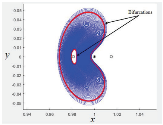
Figure 3: Planar orbits around of the equilibrium point L1 considering μ*=10-5 and d = 0. The color figure can be viewed online. 

In Figure 3, the red orbits indicate where bifurcations occur, that is, when one of the stability indices s1 or s2 reaches the critical value 2. Note in Figure 3 that the maximum position reached by the infinitesimal mass body in the x component, when the second bifurcation occurs, is greater than the position of the secondary body.

Although many bifurcations exist in dynamical systems, only two types of bifurcation are of particular interest for the focus of this work; the pitchfork and period-multiplying bifurcations.

A family of periodic orbits undergoes a pitchfork bifurcation when the stability of the periodic orbit changes as a parameter evolves, which in our case is the energy constant. During this type of local bifurcation, a pair of eigenvalues (non-trivial) of the monodromy matrix pass through the critical values λ1=1/λ1 (or λ2=1/λ2) = + 1 of the unit circle. Consequently, the stability index passes through s1 (or s2) = 2 Bosanac(2016). In addition, the stability of the periodic orbits changes along a family, and an additional family of a similar period is formed. This new family of orbits has the same stability as the members of the original family before the bifurcation arose. On the other hand, a period-doubling bifurcation is identified when a pair of non-trivial eigenvalues (λ1,2 and 1/λ1,2, where λ1,2 means λ1 or λ2), passes through λ1,2=1/λ1,2=-1 of the unit circle. Therefore, it represents a critical value of the stability index, such that s1,2 = -2 Bosanac(2016).

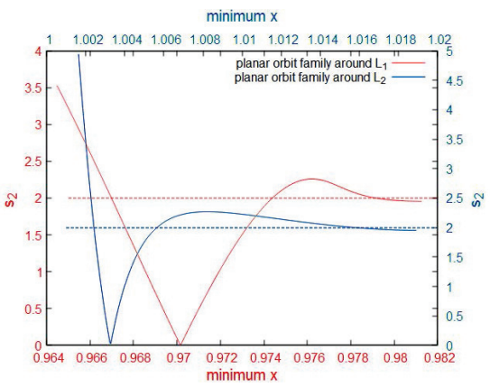
When building the families of planar orbits, with d = 0 and μ* = 10-5, we observe that the stability index (s2) reaches the critical value three times for planar orbits around L1 and L2, as seen in Figures 4. In both figures, the horizontal axis displays the minimum x value along the orbits. The stability index s1 does not reach the critical value for this μ* and d.

For μ*=10-5, the equilibrium point L1 is located at x = 0.981278, y = 0 and z = 0, while L2 is at position x =1.01892, y = 0 and z = 0. The orbits with smaller amplitudes are close to the equilibrium point (right side of Figures 4) and the first bifurcation occurs for a small amplitude orbit (x  0.97583 for L1 and x  1.01577 for L2). As we continue the planar family, the stability index s2 shown in Figure 4 continues to increase, reaches a maximum, decreases and reaches the value 2 again, where another bifurcation occurs, with x  0.99408 for L1 and x  1.0056 for L2. As we continue the families of planar orbits around L1 and L2, the stability index decreases, reache a minimum, increases and again and reaches the critical value 2, where another bifurcation occurs. After the third bifurcation, the stability index further increases and we did not detect additional bifurcations given that, as the orbits are very close to the center of mass of the secondary body, our Newton method looses track of planar orbits, converging to a completely different family of orbits.

Figure 4: Stability index (s2) around L1 (red) and L2 (green) considering d = 0 and μ*=10-5. The color figure can be viewed online. 

Figures 5 (a), (b) and (c) provide information about the types of the bifurcations that occur along the family of planar orbits. For μ*=10-5 and d = 0, analyzing the path of the characteristic multipliers in Figures 5 (a) and (b), we find that the first bifurcation is a supercritical pitchfork bifurcation, while the second one corresponds to a subcritical pitchfork case. This suggests that new families of periodic orbits appear in those regions when the bifurcation occurs Feng et al.(2016). In fact, after the first bifurcation (low amplitude periodic orbit), it is possible to detect halo orbits, while after the second bifurcation the family of axial orbits appears Grebow(2006). Unlike the planar Lyapunov orbits, halo and axial orbits are three-dimensional.
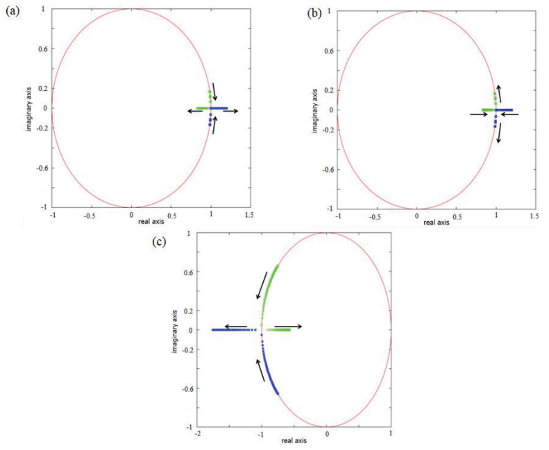
Figure 5: (a) Behavior of the characteristic multipliers at the first pithckfork bifurcation around L1 and L2. (b) Behavior of the characteristic multipliers at the second pithckfork bifurcation around L1 and L2. (c) Behavior of the characteristic multipliers that leads to the period-doubling bifurcation around L1 and L2. In these cases we consider d = 0 and μ* = 10-5. The color figure can be viewed online. 

Figure 5 (c) shows the behavior of the eigenvalues at the third bifurcation. The characteristic multipliers start in the imaginary plane and move until they collide on the negative real axis and start to reach only real values on the negative axis. Thus, the eigenvalues indicate a period-doubling bifurcation.

Figure 6 and 7 provides information about the stability index (considering the values of s2), around L1 and L2, respectively, when we increase the dipole dimension from 0 meters, that is, the body is modeled as a mass point, up to the dimension of 2000 meters. In this analysis we consider the constant mass ratio in the value of μ* = 10-5. When we consider the dipole as a point mass body (d = 0), it is possible to observe three bifurcations (the red curve passes through the critical value three times). We can observe that as we increase the dimension of the secondary, the second bifurcation points in the planar orbits around L1 and L1 cease to exist because the trajectories collide with the secondary body. This is because, as the dimension of the dipole varies and the planar orbits approach the secondary body, our Newton method looses track of the planar orbits, converging to a completely different family of the orbits. Note that, the larger the dipole size, the smaller the planar orbit family found.
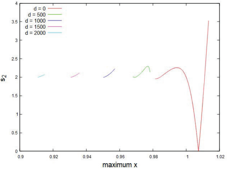
Figure 6: Planar orbit stability index around L1 for different values of d. The color figure can be viewed online. 

Figure 7: Planar orbit stability index around L2 for different values of d. The color figure can be viewed online. 

4.2 Influence of the Mass Parameter and the Size of the Dipole on the Planar Orbits

Now, we investigate how the planar orbits evolve as a function of the dipole size and mass ratio in canonical units. With the normalization factor being D = 12000 meters, the dipole sizes used in our study were d = 0, 500, 1000, 1500 and 2000 meters.

Figures 8 provide information about the stability index s1 of the planar orbits around L1, respectively, as a function of d and μ*. In both figures, the color code accounts for the size of the dipole (d).
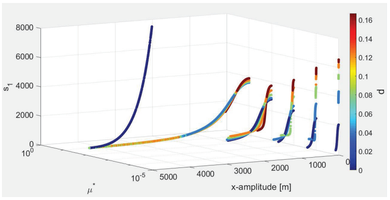
Figure 8: Stability index (s1) of the planar orbits around L1 for different values of d and μ*. The color figure can be viewed online. 

First, we investigate the solutions as d varies and μ* is kept constant. Note that, in Figures 8, in general, when the size of the dipole increases, the planar orbits become more unstable. This means that the larger the secondary body, the more unstable the planar orbits are.

If we consider d = 0, which corresponds to the CRTBP, we observe that as μ* increases, the orbits become increasingly unstable. On the other hand, when the elongated form of the secondary body is taken into account, s1 becomes smaller as μ* increases, and it only increases again after μ* = 10-1. This information is important for space missions, since a high value in the stability index (s i ) indicates a divergent mode that moves the spacecraft away from the vicinity of the orbit quickly. In general, the stability index is directly related to the space vehicle’s orbital maintenance costs and inversely related to the transfer costs. This same analysis was performed around the L2 equilibrium point, where we found similar results.

Next, we analyze the period of the planar orbits in terms of d and μ* around L1. As shown in Figures 9, for low amplitude, as d increases, with μ* kept constant, the period of the planar orbits decreases. This is because the mass distribution of the secondary body allows part of the mass of the asteroid to be closer to the negligible mass particle, causing the gravitational attraction to become larger, thus increasing the acceleration in the vicinity of the secondary body and decreasing the orbital period. On the other hand, when the x-amplitude is large, the results can be inverted, as shown in Figure 9. In general, when the amplitude of the orbit increases, the orbital period becomes longer. Similar results were found in the vicinity of L2.
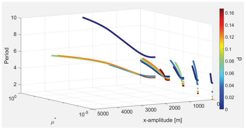
Figure 9: Period of planar orbits around L1 for different values of d and μ*. The color figure can be viewed online. 

Considering the family with d = 0, when μ* increases the period of the orbits remains similar, except when μ* = 10-1. Conversely, when the elongation of the secondary body is considered, in general, for a given value of d the larger the mass ratio, the longer the orbital period.

Finally, we analyze the energy of the system in terms of d and μ*, as shown in Figure 10.
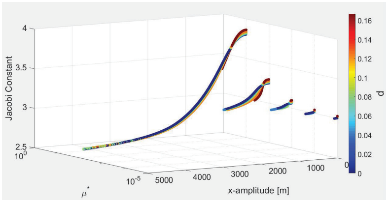
Figure 10: Jacobi constant of planar orbits around L1 for different values of d and μ*. The color figure can be viewed online. 

We find that when d or μ* increase, the energy required to orbit a given equilibrium point decreases. That is, the more elongated the secondary body and the larger the value of μ*, the less energy is needed to orbit a given equilibrium point. This also means that, as the size of the dipole increases or as the mass ratio of the system increases, the bifurcations occur at lower energies. The same analysis performed for L1 can be done for L2.

4.3 Computing Halo Orbits

Halo orbits are a three-dimensional branch of planar orbits that appear when the planar orbit stability index reaches the critical value s2 = 2. Figure 11 shows a family of halo orbits around L1 with μ* = 10-5 and d = 0. The orbits are in three-dimensional space and as the amplitude increases along the family, the halo orbits expand from the vicinity of the equilibrium point towards the surface of the secondary (black asterisk).
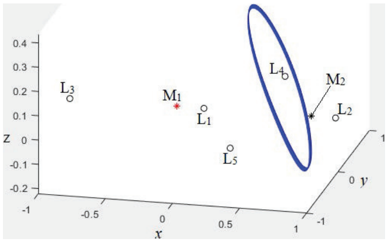
Figure 11: Halo orbits around the L1 equilibrium point considering μ*=10-5 and d = 0. The color figure can be viewed online. 

To find the initial conditions of the halo orbit, we keep the coordinate x0 fixed and search for z0*, y˙0* and T/2* such that x˙*(T/2*), z˙*(T/2*) and y*(T/2*) are all null. Then, to find the halo orbit, we use as initial guess the position x0, velocity (y˙) and period (T) of the planar orbit when the stability index s2=2. Knowing these initial conditions, all that remains is to determine the initial guess of the position on the z axis, such that we can find the halo orbit. Because the halo and planar orbit are similar (when s2=2), the position on the z axis of the halo orbit must have a very small value (almost planar orbit). Thus, in this work, the value of z0 = 0.0001 canonical units was used as the initial guess for the position on the axis z. A Newton method for this problem is

xn+1=xn-Df(xn)-1f(xn), (16)

with x = (z,y˙, T/2) and x0 = (z0,y˙0, T0/2). Here (z0, y˙0, T0/2) is the initial guess of the halo orbit.

The differential is

Df(x)=ϕ4,3ϕ4,5g4(x0,0,z(T/2),0,y˙(T/2),0)ϕ6,3ϕ6,5g6(x0,0,z(T/2),0,y˙(T/2),0)ϕ2,3ϕ2,5g2(x0,0,z(T/2),0,y˙(T/2),0), (17)

where ϕi,j are elements of the monodromy matrix, g:UR6R6 is the vector field of the restricted synchronous three-body problem, z(T/2)=ϕ3(x0,0,z,0,y,0,T/2) and y˙(T/2) = ϕ5(x0,0,z,0,y,0,T/). With this information, we expect that if x0 is close enough to the halo orbit, then xn x* as n. g is given by equation 18.

g(x,y,z,x˙,y˙,z˙)=g1(x,y,z,x˙,y˙,z˙)g2(x,y,z,x˙,y˙,z˙)g3(x,y,z,x˙,y˙,z˙)g4(x,y,z,x˙,y˙,z˙)g5(x,y,z,x˙,y˙,z˙)g6(x,y,z,x˙,y˙,z˙)=x˙y˙z˙2y˙+DxΩ-2x˙+DyΩDzΩ. (18)

All the information we need to start Newton’s method is shown above.

From the cylinder theorem, it was possible to find a halo orbit family. Thus, having found a halo orbit and noticing that it has exactly two unit eigenvalues, we can use that as a starting point to move along the cylinder. We use the initial conditions from the previous halo orbit as a starting point to find the next halo orbit at a slightly larger value of x (x coordinate closer to the secondary asteroid). If we find another halo orbit here, we iterate through the process. In this way it was possible to calculate a halo orbit family. The x coordinate step to determine each halo orbit was x = 0.00002.

4.4 Halo Orbits

Figures 12 and 13 illustrate how the halo orbits appear at the tangent bifurcations of the planar orbits around L1 and L2 when μ*=10-5 and d = 0. As we built the family of halo orbits, we observed that the amplitude of the orbits increases as the halo orbits move towards the secondary.
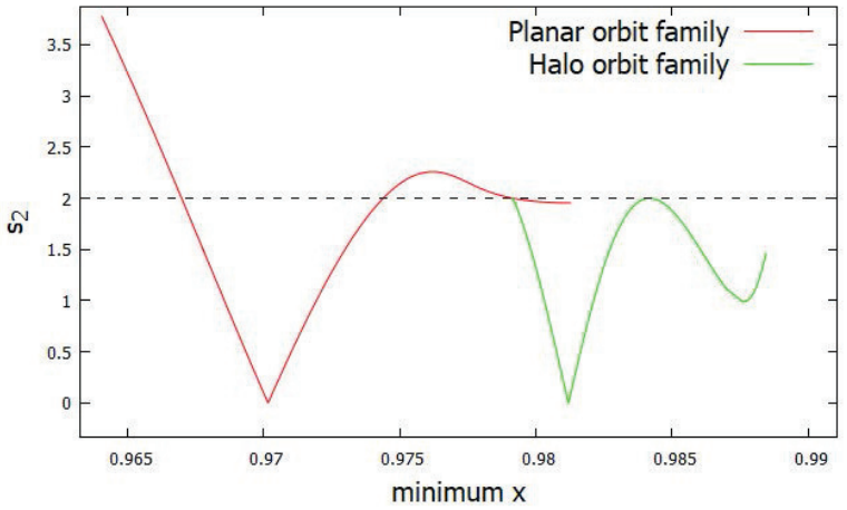
Figure 12: Stability index (s2) of the planar and halo orbit families around L1 considering d = 0 and μ* = 10-5. The color figure can be viewed online. 
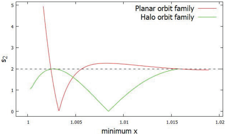
Figure 13: Stability index (s2) of the planar and halo orbit families around L2 considering d = 0 and μ* = 10-5. The color figure can be viewed online. 

For the conditions considered here, the halo orbit appears at x 0.98418 for L1 and at x 1.01575 for L2. Figure 14 shows the path of the characteristic multipliers over the unit circle to the halo orbit around L1 and L2. Initially, the characteristic multipliers move in the direction shown by the purple arrows until they collide with the negative real axis, configuring a periodic doubling bifurcation. After moving subtly along the real negative axis, the characteristic multipliers return, moving in the direction of the red arrows, colliding again at -1 and then assuming imaginary values, configuring another periodic doubling bifurcation.
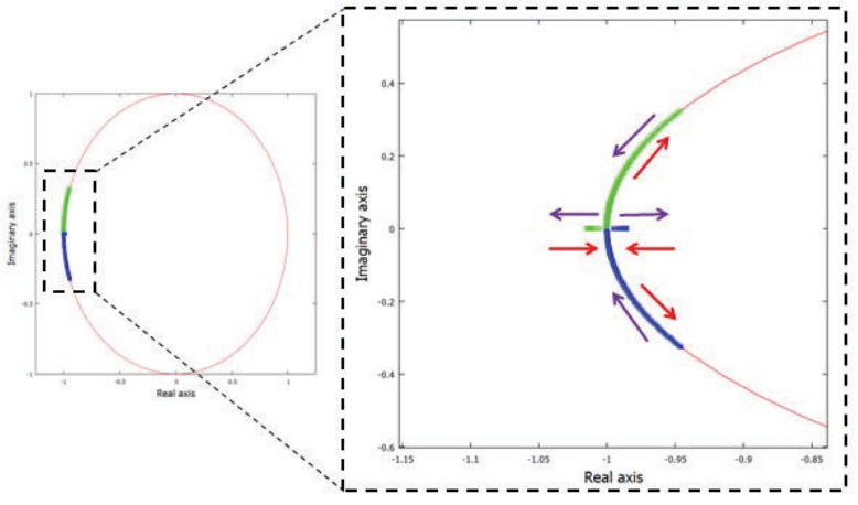
Figure 14: Behavior of the of characteristic multipliers at the period doubling bifurcation. The color figure can be viewed online. 

Figures 15 and 16 provide information about the s1 stability index as a function of d and μ*. Note that the smaller the amplitudes of the halo orbits, the larger the value of the stability index s1, when considering fixed d and μ*. As the amplitude of the halo orbit increases, the stability index decreases. If we set d = 0, we still detect stable halo orbits for small values of μ*. These orbits were also found by several authors using the restricted three-body problem and are called near rectilinear halo orbits (NRHO) Howell(1982), Zimovan-Spreen et al.(2020). NRHOs are defined as the subset of the halo orbit family with stability indexes around s i ± 2 and with no stability index considerably greater in magnitude than the others.
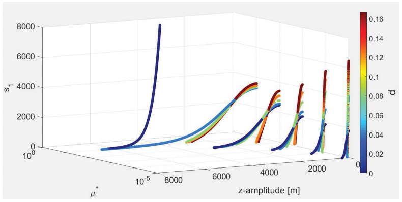
Figure 15: Stability index (s1) of halo orbits around L1 as a function of d and μ*. The color figure can be viewed online. 
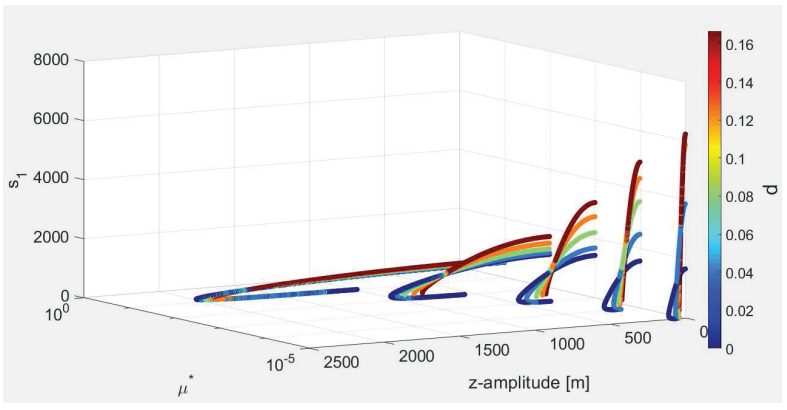
Figure 16: Stability index (s1) of halo orbits around L2 as a function of d and μ*. The color figure can be viewed online. 

Figures 17 and 18 provide information about the stability index s1 as the size of the dipole increases from 0 to 2000 meters and the mass ratio is kept constant at μ* = 10-5. The influence of the dimension of the secondary body on the stability of the halo orbits is clear in the plots. Note that, as the size of the secondary increases, the values of s1 become larger in the vicinity of the equilibrium point L1 and L2.
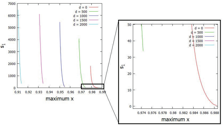
Figure 17: Halo orbit stability index around L1 for different values of d. The color figure can be viewed online. 
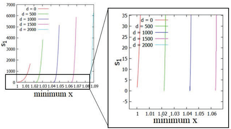
Figure 18: Halo orbit stability index around L2 for different values of d. The color figure can be viewed online. 

Note that it is unlikely to detect NRHOs around L1 when we take into account the elongated shape of the secondary body and assume small values of μ*. On the other hand, there are several NRHOs around L2. In this work, we found NRHOs up to d = 1500 meters, as shown in Figure 18.

However, as shown in Howell(1982), the stability index also depends on the mass ratio of the system. Considering d = 0 and increasing μ*, the stability index s1 increases. We did not detect any NRHO for values of μ* 10-1 and d = 0. However, we find NRHO for μ* 10-1 and d = 0 around L2. These results are similar to those obtained by Howell(1982). However, taking into account the elongation of the secondary and assuming large values of μ* (μ* 10-1), it is possible to find family members of stable halo orbits around L1 and L2. Thus, in the model used in this article, stable periodic orbits in the vicinity of irregular bodies exist, even when the secondary has a non-spherical shape. This agrees with the results obtained by Chappaz Howell(2015), who found stable orbits around L1 and L2 taking into account the elongated shape of the secondary body and considering μ = 0.4 with the triaxial ellipsoid model.

Now we analyze how the period of the halo orbits around L1 and L2 is affected by d and μ*. As d increases and μ* is kept constant, the periods of the halo orbits decrease, as shown in Figures 19 and 20.
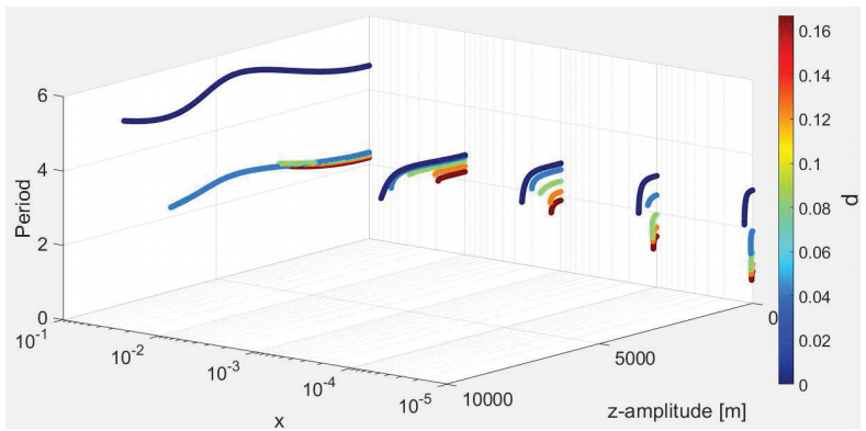
Figure 19: Period of the halo orbits around L1 as a function of d and μ*. The color figure can be viewed online. 
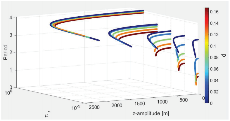
Figure 20: Period of the halo orbits around L2 as a function of d and μ*. The color figure can be viewed online. 

This is because the gravitational attraction is stronger near the particle, due to the mass distribution of the secondary body, causing the acceleration to increase and the orbital period to decrease. As the amplitude of the halo orbit increases, its orbital period becomes shorter.

Considering the elongated shape of the asteroid, but keeping d constant and increasing μ*, we notice that the period of the halo orbits become longer. This is because, as μ* increases, the equilibrium point move away from the secondary body, thus the halo orbits are further away from the secondary body, which causes the gravitational acceleration to decrease, and thus the orbital period of the particle along the orbit to increase.

Figures 21 and 22 provide information on the behavior of the Jacobi constant of the halo orbits as a function of d and μ*. Note that when d or μ* increase, the range of value of the Jacobi constant also increases. This is important information in terms of the application to space missions. Note that the larger the mass ratio of the system, or the longer the secondary body, the less energy is needed for the halo orbits to branch from the planar orbits.
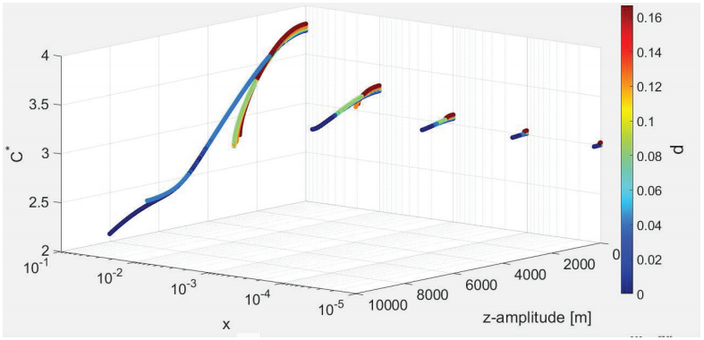
Figure 21: Jacobi constant of the halo orbits around L1 with respect to d and μ*. The color figure can be viewed online. 

Figure 22: Jacobi constant of the halo orbits around L2 with respect to d and μ*. The color figure can be viewed online. 

5 Conclusion

In this paper, the general dynamical environment in the vicinity of binary asteroid systems is explored. Based on the physical and orbital parameters of type A asteroids, the positions of the collinear balance points as a function of angular velocity were computed. We found that the locations of the collinear equilibrium points L3 and L2 are more sensitive to changes in the rotation rate, compared to L1.

Families of planar and halo orbits were computed around these equilibrium points and we found that the closer the periodic orbits are to the equilibrium point, the more unstable they are.

Numerical evidence shows that the stability of the periodic orbits around the equilibrium points depends on the size of the secondary body and on the mass ratio of the system. We observed that, the more elongated the secondary body, the more unstable the planar orbits are. Additionally, we detected unstable and stable halo orbits when d = 0 and when d  0.

Finally, we observed that, keeping the mass ratio constant, the more elongated the secondary body, the lower the orbital periods of planar and halo orbits around the equilibrium points.

Thus, if a spacecraft were to be placed in the vicinity of an equilibrium point, fuel consumption required for orbital maintenance would be higher around more elongated secondary bodies.

Acknowledgements

The authors wish to express their appreciation for the support provided by: Grants 140501/2017-7, 150678/2019-3, 422282/2018-9 and 301338/2016-7 from the National Council for Scientific and Technological Development (CNPq); Grants 2016/24561-0, 2016/18418-0, 2018/06966-8 and 2018/07377-6 from São Paulo Research Foundation (FAPESP); Grant 88887.374148/2019-00 from the National Council for the Improvement of Higher Education (CAPES); Grant E-26/201.877/2020, from Rio de Janeiro Research Foundation (FAPERJ) and to the National Institute for Space Research (INPE). This publication has been supported by the RUDN University Scientific Projects Grant System, Project No 202235-2-000

References

Aljbaae, S., Chanut, T. G. G., Carruba, V., et al. 2017, MNRAS, 464, 3552, https://doi.org/10.1093/mnras/stw2619 [ Links ]

Aljbaae, S., Prado, A. F. B. A., Sanchez, D. M., & Hussman, H. 2020, MNRAS, 496, 1645, https://doi.org/10.1093/mnras/staa1634 [ Links ]

Barbosa Torres dos Santos, L., Bertachini de Almeida Prado, A. F., & Merguizo Sanchez, D. 2017, Ap&SS, 362, 61, https://doi.org/10.1007/s10509-017-3030-2 [ Links ]

Blesa, F. 2006, Monografías del Seminario Matemático García de Galdeano, 33, 67 [ Links ]

Bosanac, N. 2016, Leveraging natural dynamical structures to explore multi-body systems, Ph-D Thesis, Purdue Universitaty [ Links ]

Broucke, R. 1969, AIAA Journal, 7, 1003, https://doi.org/10.2514/3.5267 [ Links ]

Celik, O. & Sanchez, J. P. 2017, JGCD, 40, 1390, https://doi.org/10.2514/1.G002181 [ Links ]

Chanut, T. G. G., Aljbaae, S., & Carruba, V. 2015, MNRAS, 450, 3742, https://doi.org/10.1093/mnras/stv845 [ Links ]

Chappaz, L. & Howell, K. C. 2015, CeMDA, 123, 123, https://doi.org/10.1007/s10569-015-9632-5 [ Links ]

de Almeida Junior, A. K. & Prado, A. F. B. A. 2022, NatSR, 12, 4148, https://doi.org/10.1038/s41598-022-08046-x [ Links ]

dos Santos, L. B. T., de Almeida Prado, A. F. B., & Sanchez, D. M. 2017, Ap&SS, 362, 202, https://doi.org/10.1007/s10509-017-3177-x [ Links ]

dos Santos, L. B. T., Marchi, L., Sousa-Silva, P. A., et al. 2020, RMxAA, 56, 269, https://doi.org/10.22201/ia.01851101p.2020.56.02.09 [ Links ]

Feng, J., Noomen, R., Visser, P., & Yuan, J. 2016, AdSpR, 58, 387, https://doi.org/10.1016/j.asr.2016.04.032 [ Links ]

Ferrari, F., Lavagna, M., & Howell, K. 2016, CeMDA, 125, 413, https://doi.org/10.1007/s10569-016-9688-x [ Links ]

Grebow, D. J. 2009, Master of Science in Aeronautics, Thesis, Purdue University [ Links ]

Haapala, A. F., Howell, K. C., & Folta, D. C. 2015, AcAau, 112, 1, https://doi.org/10.1016/j.actaastro.2015.02.024 [ Links ]

Howell, K. C. 1982, AsDyn, 1981, 528 [ Links ]

Jacobson, S. A. & Scheeres, D. J. 2011, Icar, 214, 161, https://doi.org/10.1016/j.icarus.2011.04.009 [ Links ]

Lan, L., Yang, H., Baoyin, H., & Li, F. 2017, Ap&SS, 362, 169, https://doi.org/10.1007/s10509-017-3148-2 [ Links ]

Liu, X., Baoyin, H., & Ma, X. 2011, Ap&SS, 333, 409, https://doi.org/10.1007/s10509-011-0669-y [ Links ]

Margot, J.-L., Pravec, P., Taylor, P., Carry, B., & Jacubson, S. 2015, Asteroids IV, ed. P. Michael, F. E. De Meu, & W. F. Bottke (Tuczon, AZ: UAP), 355, https://doi.org/10.48550/arXiv.1504.00034 [ Links ]

McCuskey, S. W. 1963, Introduction to celestial mechanics (Reading, MA: Addison-Wesley Pub. Co) [ Links ]

Meyer, K. R. & Hall, G. R. 1992, Sci, 255, 1756 [ Links ]

Pravec, P., Scheirich, P., Kušnirák, P., et al. 2006, Icar, 181, 63, https://doi.org/10.1016/j.icarus.2005.10.014 [ Links ]

Pravec, P. & Harris, A. W. 2007, Icar, 190, 250, https://doi.org/10.1016/j.icarus.2007.02.023 [ Links ]

Pravec, P., Scheirich, P., Kušnirák, P., et al. 2016, Icar, 267, 267, https://doi.org/10.1016/j.icarus.2015.12.019 [ Links ]

Riaguas, A., Elipe, A., & Lara, M. 1999, Impact of Modern Dynamics in Astronomy, Colloquium 172 of the International Astronomical Union, 169 [ Links ]

Riaguas, A., Elipe, A., & López-Moratalla, T. 2001, CeMDA, 81, 235 [ Links ]

Santos, L. B. T., Marchi, L. O., Aljbaae, S., et al. 2021, MNRAS, 502, 4277, https://doi.org/10.1093/mnras/stab198 [ Links ]

Scheeres, D. J., Van wal, S., Olikara, Z., & Baresi, N. 2019, AdSpR, 63, 476, https://doi.org/doi:10.1016/j.asr.2018.10.016 [ Links ]

Szebehely, V. 1967, Theory of orbits. The restricted problem of three bodies (New York, NY: Academic Press) [ Links ]

Tardivel, S. & Scheeres, D. J. 2013, JGCD, 36, 700, https://doi.org/10.2514/1.59106 [ Links ]

Walsh, K. J., Richardson, D. C., & Michel, P. 2008, Natur, 454, 188, https://doi.org/10.1038/nature07078 [ Links ]

Walsh, K. J. & Jacobson, S. A. 2015, Asteroids IV, ed. P. Michel, F. E. DeMeo, & W. F. Bottke, University of Arizona Press, 375, https://doi.org/10.48550/arXiv.1506.06689 [ Links ]

Wang, W., Yang, H., Zhang, W., & Ma. G. 2017, Ap&SS, 362, 229, https://doi.org/10.1007/s10509-017-3206-9 [ Links ]

Wen, T. & Zeng, X. 2022, AdSpR, 69, 2223, https://doi.org/10.1016/j.asr.2021.12.021 [ Links ]

Werner, R. A. 1994, CeMDA, 59, 253, https://doi.org/10.1007/BF00692875 [ Links ]

Yang, H.-W., Zeng, X.-Y., & Baoyin, H. 2015, RAA, 15, 1571, https://doi.org/10.1088/1674-4527/15/9/013 [ Links ]

Yang, H.-W, Baoyin, H., Bai, X., & Li, J. 2017, Ap&SS, 362, 27, https://doi.org/10.1007/s10509-017-3007-1 [ Links ]

Zeng, X., Jiang, F., Li, J., & Baoyin, H. 2015, Ap&SS, 356, 29, https://doi.org/10.1007/s10509-014-2187-1 [ Links ]

Zeng, X., Gong, S., Li, J., & Alfriend, K. T. 2016, JGCD, 39, 1223, https://doi.org/10.2514/1.G001061 [ Links ]

Zeng, X., Baoyin, H., & Li, J. 2016, AJ, 361, 14, https://doi.org/10.1007/s10509-015-2598-7 [ Links ]

Zeng, X., Zhang, Y., Yu, Y., & Liu, X. 2018, AJ, 155, 85, https://doi.org/10.3847/1538-3881/aaa483 [ Links ]

Zhang, R., Wang, Y., Shi, Y., & Xu, S. 2020, AcAau, 177, 15, https://doi.org/10.1016/j.actaastro.2020.07.006 [ Links ]

Zimovan-Spreen, E. M., Howell, K. C., & Davis, D. C. 2020, CeMDA, 132, 28, https://doi.org/10.1007/s10569-020-09968-2 [ Links ]

Received: May 15, 2022; Accepted: October 05, 2022

S. Aljbaae, Allan Kardec de Almeida Jr, & L. B. T. dos Santos: Division of Space Mechanics and Control. National Institute for Space Research, INPE. São José dos Campos, Brazil.

Allan Kardec de Almeida Jr: Instituto de Telecomunicações, 3810-193 Aveiro, Portugal (allan.junior@inpe.br).

P. A. Sousa-Silva: S˜ao Paulo State University, UNESP. São João da Boa Vista, Brazil (priscilla.silva@unesp.br).

M. O. Terra: Technological Institute of Aeronautics, ITA. São Paulo dos Campos, Brazil (maisa@ita.br).

D. M. Sanchez: The University of Oklahoma, Norman OK, USA.

A. F. B. A. Prado: Postgraduate Division - National Institute for Space Research (INPE), São Paulo, Brazil (antonio.prado@inpe.br).

A. F. B. A. Prado: Professor, Academy of Engineering, RUDN University, Miklukho-Maklaya street 6, Moscow, Russia, 117198 (antonio.prado@inpe.br).

F. Monteiro: National Observatory, ON. Rio de Janeiro, Brazil (filipeastro@on.br).

Creative Commons License This is an open-access article distributed under the terms of the Creative Commons Attribution License