Introduction
Total Hip Arthroplasty (THA), is one of the most successful surgical treatments for osteoarthritis [1] [2]. More than half a million THA procedures take place in the United States and United Kingdom per year. The surgery involves the resection of the neck and head of the femur and part of the acetabulum cup in order to introduce an implant to replace the structure and function of the joint [3] [4].
Bones are exposed to frequent mechanical stimulation and they have the ability to reorganize their own topology and adapt to the loads applied over osseous structure. This principle, known as the Wolff Law, states that the osseous remodelling (deposition or reabsorption of bone tissue) depends on the amount of mechanical stimulation [5]. However, when an implant is introduced in the femur, bone resorption (loss of adjacent bone) may appear due to stress shielding. Stress shielding is an undesirable result of the difference in stiffness between the prothesis and the natural material they replace [6].
Mechanically speaking, it is necessary that the hip implant withstands the mechanical loads inside the hip during daily activities. To avoid progressive and allocated damage, various design techniques have surfaced to create a new type of hip implant made with microstructure of a cell-like array. This means that instead of being a totally solid implant, it is a material manufactured by layers with pores. Modifying the structural properties of the implant causing a reduction of the stiffness. This will reduce stress shielding and prevents osteolysis. In addition, the optimization of pore size in the implant could improve the deformation interface between bone and implant [7].
The life expectancy of young patients who undergo TCA is a problem when it does not match the lifetime of commercial implants, this is due to the difference in the value of modulus of rigidity between implant (femoral stem) and bone tissue, which results in an increase of stress shielding and bone resorption, which in time leads to implant loss and therefore a revision surgery is needed. The rigidity of metallic stem implants could be reduced by using porous structures. These porous structures could also promote osseointegration, and achieve a long term fixation which would avoid the problems of a revision surgery [8] [9].
Finite Element Analysis (FEA) is a very powerful tool that enables exploring possible solutions to biological problems. FEA makes it possible to predict the mechanical behaviour of hip implants. The computational simulation by finite element depends on several parameters such as: geometry, material properties, boundary conditions and constraints [10].
Additive manufacturing (AM) is the process of creating a three-dimensional object layer by layer by deposition of material. Usually, additive manufacturing techniques melt powder material to create parts with an internal network as structure. Two techniques are currently used: SLM (Selective Laser Melting) and EBM (Electron Beam Melting) [11].
Metodology
For this study a 3D scan geometrical model from a Sawbones® composite synthetic left femur was used. The geometry possessed two types of tissue; cortical and trabecular bone. The numerical analysis was performed in 3 models: healthy femur, femur implanted with a commercial prosthesis (Corail DePuy®, size 11), and femur implanted with a modified prosthesis with lattice structure. For the implantation, a cut was made in the healthy femur where the head and neck of the femur was dissected at 1.5-2 cm above the great trochanter towards the level of the piriform fossa, approximately at 35º of the longitudinal axis of the femur. The stem was virtually implanted according to the instructions of the company brochure and medical advice.
The solid femoral stem (DePuy® Corail size 11) shown in Figure 1, was used for the second analysis. For the third analysis, the stem geometry was modified with a creation of a lattice structure (Figure 2), through out a series of pores of diameter of 0.31 mm.
These porous series consisted in two lattice arrays. The first array was done in the frontal plane (XZ) at the proximal a zone of the femoral stem, just below the area that protrudes from the dissected region of the femur model. The second array arrangement was placed in the plane YZ so that they coincide with the pores made in the plane XZ resulting in the geometry shown in Figure 3.
Table 1 Mechanical properties of materials.
| Element Material |
Young's Modulus (GPa) |
Poisson's Ratio |
Density (kg/cm) |
|---|---|---|---|
| Cortical bone |
17 | 0.3 | 1740 |
| Trabecular bone |
0.07 | 0.2 | 730 |
| Implant Ti6Al4V |
114 | 0.3 | 4440 |
| Head of
implant CoCrMo |
220 | 0.33 | 8830 |
| Acetabular cup |
17 | 0.3 | 1740 |
Once the 3 FEA models were prepared, the properties of the materials and the boundary conditions used for the simulations were introduced in a CAE Software, ANSYS Workbench 16®. For this study, the properties of the materials were considered as elastic and isotropic. For the static analysis, each model had a set of forces acting on the biomechanical system, which represent in a simplified way the forces resulting from a person standing on his left leg. The boundary conditions are shown in Table 2 and Figure 4.
Table 2 Boundary conditions for the analysis.
| Condition | Description |
|---|---|
| Interactions |
|
| Body Weight |
|
| Muscle |
|
| Constants |
|
In the simulation the forces of body weight are applied on an acetabular cup and the force of the greater abductor muscle was located in the greater trochanter region in order to simplify the study [12]. The computational model was meshed with tetrahedral volumes, with a maximum size per element of 0.5 mm, resulting in 3587419 nodes and 2127813 elements on average for each of the 3 models.
Results and discusion
Displacement
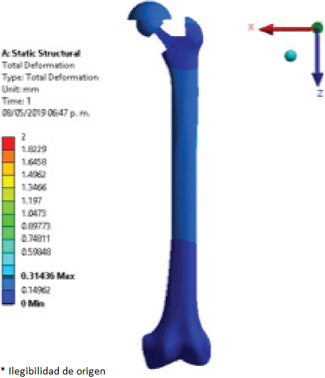
Femur deformation was evaluated for the three different models (healthy femur, femur implanted with commercial prosthesis, and femur implanted with modified prosthesis with lattice structure, shown in Figure 5 through to Figure 7 respectively). The displacement caused to the models was measured in millimetres which for the model of healthy femur a maximum displacement of 0.281 mm was obtained. The displacement values of the models implanted with a commercial prosthesis and implanted with a modified prosthesis with a lattice structure were 0.314 mm for both cases.

Figure 7 Displacement (mm) of the femur implanted with modified femoral stem with lattice structure.
The close similarity of the results obtained for maximum displacement in the implanted models may be caused by the fact that the lattice structure did not have the most optimal pore size for this application, since most of the femoral stem still has a solid structure and identical to the commercial stem, in addition to the lattice geometry used, i.e. circular pores, which might have not been the most suitable geometrical shape for this application and mechanical transfer of loads.
Elastic Strain
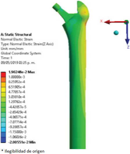
To compare the elastic strain in the different regions of interest, the surfaces of the femur were divided using the Gruen zones, established as shown in Figure 8 through to Figure 11 show the elastic strain obtained in the characteristic tension and compression areas in each model studied. The average values of the elastic strain found in the Gruen zones can be seen in Table 3, Table 4, and Table 5.

Figure 11 Elastic strain (mm/mm) of femur implanted with modified femoral stem with lattice structure.
Table 3 Average values of elastic strain (mm/mm) in the healthy femur.
| Zones | Elastic Strain (mm/mm) |
|---|---|
| I | 3.98e-4 |
| II | 1.91e-4 |
| III | 2.36e-4 |
| IVA | 2.01e-4 |
| IVB | -4.65e-4 |
| V | -4.23e-4 |
| VI | -4.11e-4 |
| VII | -7.65e-4 |
Table 4 Average values of elastic strain (mm/mm) of femur implanted with commercial prosthesis.
| Zones | Elastic Strain (mm/mm) |
|---|---|
| I | 6.17e-4 |
| II | 3.01e-4 |
| III | 3.84e-4 |
| IVA | 3.06e-4 |
| IVB | -3.69e-4 |
| V | -3.35e-4 |
| VI | -2.34e-4 |
| VII | -1.8e-4 |
Table 5 Average values of elastic strain (mm/mm) in the femur implanted with the modified prosthesis with lattice structure.
| Zones | Elastic Strain (mm/mm) |
|---|---|
| I | 5.85e-4 |
| II | 3.49e-4 |
| III | 3.22e-4 |
| IVA | 3.37e-4 |
| IVB | -3.79e-4 |
| V | -2.47e-4 |
| VI | -2.23e-4 |
| VII | -1.55e-4 |
The values obtained in the present work for each of the regions of tension and compression are similar to those shown by Moya [12]. These values obtained for elastic strain, expressed by the tension and compression regions, are a characteristic behaviour in the structure of the femoral bone. The load distribution performed by the internal trabecular networks achieve this effect by directing the loads to the femur’s longitudinal structure (shaft), and to the external periphery [13].
Stress
Finally, the last point to evaluate was the equivalent stress to analyse the effect of the loads through their structures for the three models. For this, a point at the compression area and at the middle of the proximal region of the femur was selected, the maximum value of stress was compared with the results obtained in the work of Moya [12]. The results obtained by Moya, for the healthy femur and femur implanted with a commercial prosthesis were of 16 MPa and 13 MPa respectively.
The intact model seen in Figure 12 showed a superficial stress of 8.9 MPa at the zone of interest. The resulting stress for the model implanted with a commercial prosthesis was of 7.51 MPa, and the model implanted with a modified prosthesis with a lattice structure showed a superficial stress of 7.17 MPa at the zone of interest.
The implanted models achieved a considerable reduction of superficial stress compared to the healthy femur. The model implanted with a lattice structure was expected to reduce the superficial stress much more than the model implanted with the commercial prosthesis, but the results are similar to those obtained with the commercial femoral stem. Nevertheless, the model implanted with a modified prosthesis with lattice structure presents a small reduction of stress.
Conclusions
The search to create a better design of femoral stem for total hip arthroplasty has led to the implementation of innovative design and manufacturing methods with new geometries, structures and materials. in order to have a closer approach to the mechanical characteristics of a healthy femur, and to improve the implantation of the hip prosthesis, promote osseointegration and prolonging the life of the implant and therefore, to improve the quality of life of the patient.
The results obtained were very similar between the model implanted with a commercial prosthesis and the model implanted with a modified prosthesis with a lattice structure. For this reason, it is necessary to continue making tests with different lattice structures of smaller dimensions in the ranges of 500 microns, and if possible, betting on -nano dimensions. To achieve the objective that the properties of the femoral stem resemble the properties of the osseous tissue of the femur, to avoid high shielding stress, bone resorption and consequently loosening of the implant.
As future work, the objective is to design through lattice structures, an arrangement of artificial trabeculae to efficiently transport and direct the loads through the walls of the femoral shaft.


 nueva página del texto (beta)


