


 text new page (beta)
 English (pdf)
 Article in xml format
 Article references
 Send this article by e-mail
 Cited by SciELO
  Similars in
SciELO
Similars in
SciELO 
 Permalink
1. Introduction
DC-DC converters are usually employed to convert DC voltage from one level to lower or higher level. Recently, the DC-DC converters have been widely used in various applications (Kanimozhi & Rabi, 2019; Méndez-Díaz, Pico, Vidal-Idiarte, Calvente, & Giral, 2018; Rashmi & Uplane, 2019;). In (Rashmi & Uplane, 2019), the authors studied the advantages and disadvantages of converter topologies for maximum power-point tracking applications. In (Nanwani & More, 2018), the authors proposed a novel buck-boost converter for photovoltaic systems with a transformerless inverter. In (Chen, Pise, Elmes, & Batarseh, 2019), the authors proposed a high efficient buck-boost converter for portable battery devices. In (Jamshidpour, Poure, & Saadate 2019), the authors utilized the two-stage DC-DC converters for energy harvesting applications. In (Sekhar, 2019), the authors implemented the buck converter for low power applications. In (D'Antonio, Chuan, Wu, & Khaligh, 2019), the author designed and optimized the buck converter for space exploration applications. In (Babu, Chary, Abdullah, Elangovan, & Karuppa, 2019), the authors discussed applications of buck converters for electrical vehicle systems.
In order to provide reliable performance, it is necessary to design an efficient and robust controller for the buck-converter system. For example, In (Yuan, Chang, Zhou, Huang, & Xu, 2015), the authors designed a fuzzy PID controller based on the genetic algorithm for a buck converter. In (Kanzian, Agostinelli, & Huemer, 2016), the authors designed a digital controller for the DC-DC converter. In (Cheng et al., 2016), the output voltage of the DC-DC converter was regulated to the desired voltage through the fast and finite-time adaptive method. In (Abdissa & Chong, 2017), the model predictive control method is proposed to control the output voltage of the DC-DC converter. In (Bhattacharyya, Padhee, & Pati, 2019), the authors utilized the feedback linearization method to control the output voltage of the step-down converter. In (Nizami, Chakravarty, & Mahanta, 2017), the authors designed an efficient controller based on the neural network back stepping controller for a step-down converter fed permanent magnet DC motor.
Because of the simple structure and robust behavior against parametric uncertainty and external disturbances, the sliding mode control (SMC) has become a popular method. SMC has been applied successfully to a variety of systems such as medical systems (Badfar & Ardestani, 2019; Badfar, Ardestani, & Beheshti, 2020), mechanical systems (Amirkhani, Mobayen, Iliaee, Boubaker, & Hosseinnia, 2019; Bessa, Otto, Kreuzer, & Seifried, 2019; Peza-Solis, Silva-Navarro, & Castro-Linares, 2015) and electrical converters (Asgari, 2019; Li, Liu, & Su, 2019). Recently, the terminal sliding mode control (TSMC) has been introduced to guarantee the finite-time convergence and higher precision of tracking error (Du, Chen, Wen, Yu, & Lü, 2018). The main drawback of this scheme is the singularity problem in the control input signal (Feng, Yu, & Han, 2013). In other words, when the system states approach the origin in the phase plane, the control input signal becomes infinitely large. The nonsingular terminal sliding mode control (NTSMC) is suggested to overcome the singularity issue (Corradini & Cristofaro, 2018). In order to reduce the chattering problem, intelligent methods are utilized to prevent it. For example, the genetic (Farahmandrad, Ganjefar, Talebi, & Bayati, 2020) and neural network (Rahmani, Ghanbari, & Ettefagh, 2018) algorithms are used to reduce the chattering problem.
According to the authors’ best knowledge, this is the first attempt to design an adaptive NTSMC using supervisory fuzzy control to control the output voltage of the buck converter. Compared to the previous studies on this issue (Ma, Zhang, Yang, Ding, & Dong, 2018; Pandey, Patil, Ginoya, Chaskar, & Phadke, 2019; Wang, Li, & Li, 2020), this research attempts to avoid the singularity problem in the control input signal and also proposes the hysteresis modulation and fuzzy supervisory method to prevent high frequency of MOSFET switching. Motivated by the above discussions, the contributions of this research are summarized as follows
The finite-time convergence is ensured in the proposed method.
The singularity problem is avoided under NTSMC.
The chattering phenomenon is reduced under a fuzzy logic system.
The proposed method adaptively tracks the output voltage when the resistance load varied.
The proposed method provides faster transient response and lower steady-state error.
The hysteresis modulation is suggested to avoid a high frequency of switching.
The rest of this paper is organized as follows: The model description is discussed in Section 2. Section 3 is devoted to the design of the controller including FTSM, NFTSM and AF-NFTSM. The simulation results, including the parametric uncertainties and measurement noise, are presented in Section 4. The concluding remarks are presented in Section 5.
2. Model description
The topology of the buck converter is depicted in Fig. 1. In this topology, the Vin is DC voltage source, SW is MOSFET transistor, D is a diode, R is resistance load, and L,C are inductor and capacitor of the output filter. If the MOSFET transistor is in the ON condition, the following equations are obtained by using Kirchhoff’s voltage and current laws as follows:

Similarly, when the MOSFET transistor is in the OFF condition, the operation of the converter is governed by the following equations
With the help of state-space averaging, the operation of a DC-DC buck converter is obtained as follows:
where u is the duty cycle of the PWM signal. In order to employ the control approaches, it is recommended to express the governing equations of the buck convertor in state-space form. For this purpose, the state variables of the system are defined as follows:
Substituting (5) and (6) into the above equations yields,
Since the uncertainty is an inherent part of the dynamical system, the state-space form is written as follows
where f_n (X) and g_n (X) present the nominal values and L(X,t) presents the Lumped uncertainty which satisfies the following condition
where δ is a positive constant.
3. Control Objectives
Our main control objectives provide faster transient response and lower tracking error.
It is also desirable to regulate the output voltage of the converter to the desired voltage in the finite time, i.e.,
where t is the simulation time.
3.1. SMC
As shown in Fig. 2, the SMC consists of two phases. In the first phase, the state variables of the system move toward the sliding line in the phase plane. The equivalent control law is responsible for the first phase. In the second phase, the state variables of the system slide along the sliding line towards the origin in the phase plane. The switching control law is responsible for the second phase.

The traditional sliding surface is defined as follows:
where λ>0 is a design parameter
Remark 1. When the sliding mode occurs (STra=0), the finite-time convergence of the state variables is not ensured under the traditional sliding mode control.
Proof. The dynamics of the sliding surface in the sliding mode is obtained as follows:
Substituting from (13) into (14) yields:
The solution of (14) is achieved as follows:
It is understood that the finite-time convergence is not achieved in this method. In order to tackle this problem, the terminal sliding mode is suggested in the next sub-section.
3.2. TSMC
In order to guarantee the finite-time convergence, the terminal sliding mode is proposed. In this method, the nonlinear sliding manifold is introduced as follows:
where λ>0 is a design parameter, the constants p>q>0 are positive odd integers.
Remark 2. When the sliding mode occurs, the state variables of the system converge to the zero in the finite-time as follows:
Proof. When the sliding mode occurs:
Substituting (17) into the above equation yields:
Equation (20) can be written as:
Taking the integral of both sides along the time yields:
The proof is complete.
Definition1. The sufficient condition for the existence of terminal sliding mode is
where η is a positive constant.
Theorem 1. The output voltage of the buck converter converges to the desired voltage asymptotically if the sliding surface is chosen as (17) and the control input signal is adopted as follows;
where KT>0 switches gain.
Proof. The positive-definite Lyapunov candidate function is considered as follows:
Taking its derivative along the time yields:
Substituting (17) into (26) yields
Substituting (9) into the above equation yields:
Substituting (24) into (28) yields:
where η is a positive constant. According to the Lyapunov theorem, the control input signal (24) regulates the output voltage of the buck converter to the desired voltage if the following equation is hold:
The proof is complete.
Remark 3. As shown in Fig. 3, if the system states are within set {(x1, x2)| x1→0,x2≠0}, the control input signal is unbounded. In this case, the stability and safety of the system cannot be guaranteed. This condition appears by the singular term in the control input signal (24) as follows:

In the next subsection, the nonsingular terminal sliding mode control is proposed to overcome the singularity problem in the control input signal.
3.2. NTSMC
In this subsection, a novel approach is proposed to satisfy both finite-time convergence and singularity avoidance. The nonlinear sliding manifold is selected as follows:
Taking its derivative along the time yields:
Substituting (9) into (33) yields:
The equivalent control law is obtained by ignoring the uncertain term and checking the invariance condition (SNTSMC (X)=0) as follows:
The switching control law is selected as follows:
where KN>0 switches gain.
The control input signal (u(t)=uEQU(t)+uSW (t)) converges the state variables of the buck converter to the desired values in the finite-time under the nonsingular sliding manifold (32).
3.2.1. Stability analysis
In this subsection, the stability of the closed-loop system is investigated by the Lyapunov theorem. The positive-definite Lyapunov candidate function is considered as follows:
Taking its derivative along the time yields
Substituting (32) into (38) yields:
Substituting (9) into (39) yields:
Substituting (35) and (36) into the above equation yields:
In other words, the proposed method controls the output voltage of the buck converter to the desired voltage in the finite-time in the presence of parametric uncertainty and external disturbances if the switching gain is adopted as follows:
Remark 4. Similarly, to the TSMC, the state variables of the system converge to the zero in the finite-time as follows:
Remark 5. The singularity problem in the nonsingular sliding mode controller (28) will be avoided as long as the following condition holds:
Remark 6. The converter exhibits an adaptive performance when the resistance load is changed if the value of λ is selected as follows:
Remark 7. The switching action can be defined as:
where h is the bandwidth of hysteresis modulation.
3.2.2. Fuzzy Logic System
The fuzzy logic system is suggested to reduce the chattering problem. In this novel method, the switching gain is scheduled according to fuzzy rules. The structure of the fuzzy logic system is depicted in Fig. 3. In this method, the sliding surface and its differential are selected as the inputs and the switching gain is selected as the output. As shown in Fig. 4 and Fig. 5, the triangle membership function with 50% of overlapping is suggested. The fuzzy variables are defined as NB (Negative Big), NS (Negative Small), Z (Zero), PS (Positive Small), PB (Positive Big). Next, the rules of the fuzzy system are developed with the sliding surface and its derivative as a premise and switching gain as a consequent. A typical fuzzy rule is defined as follows


where
The fuzzy rules of the AFGS method are presented in Table 1. Finally, the method of center average defuzzification is employed to achieve the crisp value of the outputs.
Table 1 Fuzzy rules.
|
|
S(X) | ||||
|
|
NB | NS | Z | PS | PB |
| NB | PB | PB | PS | PS | Z |
| NS | PB | Z | PS | PB | PS |
| Z | NS | NS | Z | Z | PB |
| PS | NS | Z | NS | NS | Z |
| PB | Z | NS | Z | NS | PB |
Remark 8. According to Fig. 4, the control input signal in this approach is expressed as:
4. Results and Discussion
In this section, some simulation results are carried out to demonstrate the efficiency of the proposed method. The simulation results are performed by Matlab/Simulink with the step size of 2μs.
The list of parameters of the buck converter is presented in Table 2. The controller coefficients are selected as q=3, p=5, λ=.6.
Table 2 Parameters of the buck converter.
| Parameter | Value |
| Input Voltage (V) | 10 |
| Desire voltage (V) | 5,2.5 |
| Resistance load (Ω) | 10 |
| Inductance (mH) | 1 |
| Capacitor (μF) | 1000 |
In the first scenario, the desired output voltage is set to 5 (V). The response of the output voltage is presented in Fig. 6.

Clearly, the proposed controller regulates the output voltage to the desired voltage. The output voltage error (7) and its derivative (8) are presented in Fig. 7. The sliding surface (32) is depicted in Fig. 8. It is concluded that the proposed fuzzy algorithm effectively reduces the amplitude of chattering.
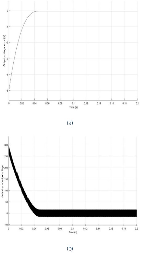
Figure 7 Response of the state variables of the system: (a) output voltage error; (b) derivative of the output voltage error.

In the second scenario, the desired output voltage is set to 2.5 (V). According to Fig. 9, the proposed controller is able to control the output voltage. Similarly, the output voltage error (7) and its derivative (8) are presented in Fig.10. The sliding surface (32) is presented in Fig. 11. In the third scenario, the performance of the controller is evaluated in the presence of parametric uncertainties and measurement noise.

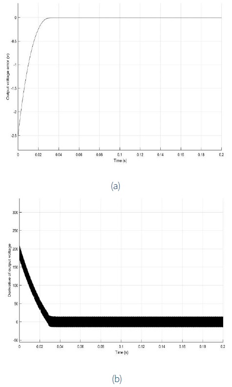
Figure 10 Response of the state variables of the system: (a) output voltage error; (b) derivative of output voltage error.

At first, the values of the capacitor, the inductor and the resistance load are deviated from the nominal values by 10%. According to Fig. 12, the proposed method shows a robust behavior in the presence of parametric uncertainties. Next, the state variables are contaminated with sinusoidal noise with amplitude .01 mv and the sampling time of 0001 s. As shown in Fig. 13, the proposed method is able to regulate the output voltage to the desired radius in the presence of measurement noise.
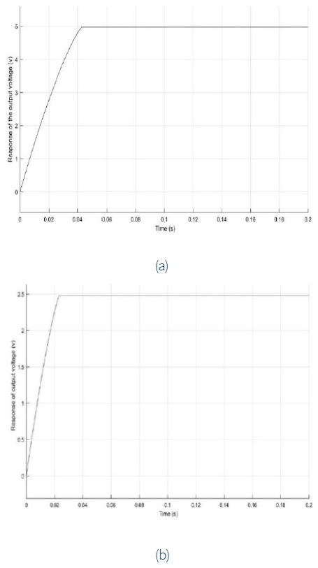
Figure 12 Performance of the controller in the presence of parametric uncertainty: (a) output voltage is set to 5v; (b) output voltage is set to 2.5v.
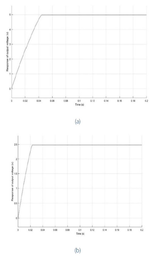
Figure 13 Performance of controller in the presence of measurement noise, (a) output voltage is set to 5v, (b) output voltage is set to 2.5v
Finally, the steady-state error is analyzed. For this purpose, three different indexes are introduced as follows:
According to Table 3, the proposed controller efficiently regulates the output voltage to the desired voltage with high precision.
Table 3 Steady-state error analysis.
| Error Indexes | Desired Voltage | ||
| Vref=2.5v | Vref=5v | ||
| IAE | 2 x 10⁻² | 1.5 x 10⁻² | |
| ISE | 1.3 x 10⁻³ | 1.42 x 10⁻³ | |
| ITEA | 1.3 x 10⁻³ | 1.14 x 10⁻³ |
Finally, a comparative study is carried out to demonstrate the efficiency of using the adaptive fuzzy gain scheduling method. For this purpose, the proposed controller is compared with the sliding mode controller (Naik & Mehta, 2017), the fast terminal sliding mode controller (FTSM) (Komurcugil, 2012) and the nonsingular fast terminal sliding mode controller (NFTSMC) (Komurcugil, 2013). According to Table 4, the use of the proposed method improved the performance of the buck converter. The time response properties were clearly improved and the steady state error decreased. it can be easily concluded that the proposed method offers a more efficient solution to control the buck converter.
Table 4 Comparison of the performance indexes of various control methods.
| Performance Index |
Method | |||
| SMC | FTSM | NTSMC | AFNTSM | |
| Rise time | .078 | .043 | .023 | .018 |
| Setting time | .085 | .066 | .045 | .023 |
| Steady-State Error |
.143 | .0143 | .0034 | .0012 |
| Over shot | .135% | .088% | .043% | .012% |
In order to verify the simulation results, the experimental results under various working conditions are presented. The experimental setup is presented in Fig. 14. In the first scenario, the voltage of the input is 20 (V) and the desired voltage is 12 (V). As shown in Fig. 15, the proposed method is successful in tracking the desired voltage. In the second scenario, the input voltage is set to 15 (V) and the desired voltage is set to 12(V). According to Fig. 16, the proposed method is able to converge to the desired voltage with high accuracy.


5. Conclusions
In this paper, we tackled the challenging problem of output voltage regulation of the buck converter through a novel control approach. At first, the governing dynamics of the buck converter are achieved and then expressed to the state-space form. Next, the nonsingular sliding mode control is adopted to control the output voltage of the buck converter. In order to prevent the chattering problem, the switching gain is adaptively scheduled according to the fuzzy rules. The coefficient of the nonlinear sliding manifold is selected according to the resistance load. The simulation and experimental results indicate the efficiency of the proposed method. This research can be developed in several directions. For example, it is possible to design the fractional-order controller and estimate the states of the converter by sliding observer. The results of this research are of immediate interest in many applications such as photovoltaic systems, satellites, and battery chargers.

