


Services on Demand
Journal
Article
 text in
  English (pdf)
 Article in xml format
 Article references
 Send this article by e-mail
Indicators
-
 Cited by SciELO
 -
 Access statistics
Related links
-
 Similars in
SciELO
Similars in
SciELO
Share

 Permalink
Revista ALCONPAT
On-line version ISSN 2007-6835
Rev. ALCONPAT vol.6 n.2 Mérida May./Aug. 2016
https://doi.org/10.21041/ra.v6i2.134
Applied research
Influence of the thickness of the coating of the elements of reinforced concrete exposed to corrosion processes and subjected to external loads
1Departamento de Ingeniería, Universidad Nacional del Sur, Bahía Blanca, Argentina.
When carrying out corrosion studies on reinforced concrete, it is important to consider the action of external loads in the tests, as this situation is the most frequent in the structures. In this work, we show the results obtained from exposing beams of reinforced concrete subjected to flexional effects, materialized with loads that generate equal tensile stress on the corroded reinforcement, to an accelerated corrosion process. The beams were manufactured with different coating thicknesses on the reinforcement and with a concrete of 25 MPa characteristic resistance. This study evidences the influence of the coating thickness of the reinforcement on the corrosion process and its external manifestation (cracking of the coating), compared with the same mechanical requests.
Keywords: corrosion of tensile reinforcement; coating; cracking
Al realizar estudios sobre corrosión en hormigón armado, es importante considerar en los ensayos, la acción de cargas externas, pues esta situación es la más frecuente en las estructuras. En este trabajo, se presentan los resultados obtenidos al exponer a un proceso de corrosión acelerada, a vigas de hormigón armado sometidas a esfuerzos flexionales, materializados con cargas, que generan iguales tensiones de tracción en las armaduras corroídas. Las vigas se fabricaron con diferentes espesores de recubrimiento de las armaduras y con un hormigón de resistencia característica 25 MPa. Este estudio pone en evidencia la influencia del espesor de recubrimiento de las armaduras, sobre el proceso de corrosión y su manifestación externa (fisuración del recubrimiento), frente a las mismas solicitaciones mecánicas.
Palabras claves: corrosión de armaduras traccionadas; recubrimiento; fisuración
Ao realizar estudos sobre corrosão em concreto armado, é importante considerar nos ensaios a ação de cargas externas, pois esta situação é mais frequente nas estruturas. Neste artigo apresentam-se os resultados obtidos ao expor vigas de concreto armado a um processo de corrosão acelerada, submetidas a esforços de flexão materializados com cargas que geram tensões constantes de tração nas armaduras corroídas. As vigas foram elaboradas com diferentes espessuras de cobrimento das armaduras e com um concreto de resistência característica de 25MPa. Este estudo coloca em evidência a influência da espessura de cobrimento das armaduras, sobre o processo de corrosão e sua manifestação externa (fissuração do cobrimento), frente às mesmas solicitações mecânicas.
Palavras-chave: corrosão de armaduras tracionadas; cobrimento; fissuração
1. Introduction
Concrete is the material most used in construction worldwide. The structures built with this material have a certain useful life, where the processes that cause its degradation affect the aesthetic and, mainly, its functionality-which becomes apparent with the appearance of stains, cracks, chipping of the coating, etc.
One of the most common pathologies that manifest in reinforced or pre-stressed concrete is the corrosion of its metallic reinforcement. The steel of the reinforcement is protected from corrosion by a passive layer of cement hydration products, comprising an alkaline environment. In marine environments, however, the chloride ions accumulate in the surface of the concrete and slowly penetrate towards its interior, until reaching the metallic reinforcement so that, after a certain concentration, they dissolve the layer that protects the steel and thus a corrosion process is initiated. These products of corrosion have a much higher volume than that of the steel from which they originate; at first, they are housed in the pore structure of the concrete, but once this is filled, internal stress begins to build up (Peralta, 2009), which in turn ends up generating cracks in the coating (Alonso, 1996; Andrade, 1993).
This cracking of the coating favors the advance of the deterioration of the affected structures, as it allows the entry of external agents (chloride, water, and oxygen) towards the reinforcement, causing a decrease of the steel section and affecting the adherence between both materials (Al-Sulaimani, 1990; Almusallam, 1996; Rodríguez, 1993). In this manner, as the deterioration advances, the section modulus of the affected structural element decreases, having negative consequences on the bearing capacity and useful life of the affected structure (Melchers, 2001; Rodríguez, 1996; Rodríguez, 1998; Torres-Acosta, 2007).
There is a series of factors that control the cracking process of the coating (Alonso, 1998), among them, the following stand out: the environment to which the structure is exposed (Aveldaño, 2011) and the properties of the concrete, in terms of the mechanical structure of the coating (Rodríguez, 1998), as well as by the need to have a pore structure to provide tightness. Therefore, within the properties of the concrete, capillary absorption (related to the pore structure) plays a rather important role, which has led to various countries dictating standards that stablish maximum values for it (Instituto Argentino de Normalización y Certificación, 2005). In previous works with beams developed with different concretes and free of external loads, carried out in the laboratory where these investigations materialized (Schierloh, 2001; Schierloh, 2003), it was established that the capillary absorption influences in the appearance of the first cracks caused by corrosion and the evolution of the corrosion potentials; during the time of the accelerated corrosion tests, no significant correlations were found between the cracking frame produced by the corrosion with the electrochemical behavior registered during the tests. Other factors to be considered in the corrosive process and its effects, are related to the manner in which the reinforcement of the structure is distributed (Aveldaño, 2009; Hariche, 2012) and the mechanical requests to which the reinforcement in the corrosion process is subjected, which are inevitably associated to the stressed state of the concrete that surrounds it (Aveldaño, 2013).
Regarding the stress state of the reinforcement, it could be said that it introduces a certain uncertainty in the corrosive processes and their consequences. Despite the importance of the topic, which in the case of the reinforcement subject to tensile stress could cause the phenomenon known as “corrosion under stress”, research on concrete structures is scarce. However, there have been some works in recent years (Calabrese, 2013; Elfergani, 2012; Fumin, 2011; Ortega, 2011). Although the reinforced concrete structures in service normally corrode under static and/or dynamic loads (for example, bridges), there have been few studies in this regard in comparison with those that analyze structures undergoing corrosion without external loads.
The expected behavior of a structure subject to the effects of corrosion and at the same time under the effects of external loads (both static and dynamic), is different from the evolution of corrosion when there are no such loads; therefore, some research was directed to the study of this topic. (Hariche et al., 2012) studied reinforced concrete beams exposed to accelerated corrosion, where the main parameters that varied in their investigations were the arrangement of the reinforcement and the magnitude of the external loads (Hariche et al., 2012; Yu et al., 2015). They analyzed the evolution of the corrosion and the cracking in beams cracked under the constant effect of external loads and exposed in a saline chamber, carrying out two sets of beams with differing casting directions, in relation to the tensile reinforcement. (Linwen, 2015 and Malumbela et al., 2009) studied beams under accelerated corrosion with applied loads well under the breaking point, where they monitored the variation of the depth of the neutral axis, the curvature, and the moment of inertia.
In this work, we present the results of tests carried out on reinforced concrete beams with different coating thicknesses, subjected to a process of accelerated corrosion and under the effect of static external loads. Said tests were meant to evaluate the behavior of the same, from the point of view of the corrosion of its reinforcement and its external (cracking of the coating of the concrete) and internal (corrosion potentials) effects. Regarding this issue, there has been a lot of work done on beams without external loads, but we found no analogous work to the one presented in this paper.
2. Experimental procedure
2.1 Materials used
The materials used in the cement mixture were the following:
Cement: Ordinary Portland Cement (OPC40) was used, which came from a factory located in the Province of Buenos Aires (the central zone of Argentina).
Fine aggregate: composed of natural silica sand that came from a deposit located to the south of the Province of Buenos Aires, which complies with the quality specifications stablished by Standard IRAM 1627 (Instituto Argentino de Normalización y Certificación, 1997).
Coarse aggregate: composed of pebbles whose Maximum Nominal Size was of 25 mm, which complies with the granulometric limits establish in Standard IRAM 1627 (Instituto Argentino de Normalización y Certificación, 1997).
The cement was elaborated with a water/cement (w/c) ratio of 0.50, a value adopted by the Argentinian standard (Instituto Argentino de Normalización y Certificación, 2005) for resistant structures that are more than 1 Km from the coast, in a zone influenced by winds with sea salt. Details on the dosage used are shown in Table 1.
2.2 Elaboration of the samples
Four reinforced cement beams in which the coating/diameter of the bars relation varied were manufactured in order to simulate different degrees of protection of the reinforcement; in addition, cylindrical test pieces were molded with the objective of characterizing their mechanical (compression and tension) and physical (capillary absorption test) behavior.
The beams had a 8 x 16 cm section and a longitude of 220 cm, the longitudinal reinforcements were corrugated steel bars of natural hardness (ADN 420, IRAM-IAS U 500-528) (Instituto Argentino de Normalización y Certificación, 1989), which is the steel used for construction in Argentina-with a diameter of 4.2 mm (two bars in the upper face and two in the lower one), and closed smooth steel abutments of: 2.1 mm in diameter, separated every 10 cm, with a coating that varied between 10 mm and 25 mm. It must be made clear that the selection of the diameters used in the tests was due to wanting to maintain the geometrical likeness of the laboratory beams (to 1/3 the size of the real structure) to the means used in real structures, therefore, bars commercially available in the country in question were used. Table 2 shows the characteristics of the reinforcement.
Table 2 Characteristics of the reinforcement.
| Type of steel | Diameter (mm) | Elastic limit (MPa) | Breaking strain (MPa) | |
|---|---|---|---|---|
| Longitudinal reinforcement | Natural hardness | 4 x 4.2 | 680 | 690 |
| Abutments | Smooth | 2.1 | 640 | 640 |
The concrete was sieved in the caissons and mechanically vibrated, moistening it during the first 7 days. Subsequently, the curing continued in a laboratory environment (temperature ≈ 20ºC, relative humidity ≈ 50%) for approximately 60 days. Cylindrical concrete test pieces (15 x 30 cm) were also elaborated, which were used in the physical capacity and capillary suction speed tests (IRAM 1871) (Instituto Argentino de Normalización y Certificación, 2005), as well as in mechanical tests: resistance to compression (IRAM 1546) (Instituto Argentino de Normalización y Certificación, 1992) and indirect tension (IRAM 1658) (Instituto Argentino de Normalización y Certificación, 1992). They were molded and cured in accordance with the standard IRAM 1534 (Instituto Argentino de Normalización y Certificación, 1985).
2.3 Accelerated corrosion process
In order to obtain the tensile stress of the superior reinforcement (which would be the one that would have been subsequently subjected to a process of accelerated corrosion), loads were placed at the extremes of the beams, adopting an intermediate area as the area to be corroded, and leaving overhangs on the two lateral sides. Figure 1 shows the adopted structural outline. The area between the supports possesses an almost constant bending stress, therefore, the entire area of the bars affected by the corrosion is subject to a stress that is practically equal in intensity, by being subjected in each case to its own weight plus the effect of various loads that varied from 90 kg to 100 kg.

The elements were subjected to accelerated corrosion for approximately 160 days through the application of an external printed current, provided by a galvanostat connected between an exposed end of the upper reinforcement (anode) and a contra-electrode (cathode) comprised of a stainless-steel mesh (of 50 cm in length and of the same width as the beam), located in its upper face. A sponge (of equal dimensions) was placed on it, which was kept moist with a controlled quantity of an aqueous solution with 0.3% (in weight) of sodium chloride (NaCl) (3 g NaCl / litter of water). Prior to connecting the galvanostat, the moistening of the central area began for 2 days in order to ensure that the entire coating had the necessary humidity to allow the circulation of the current. In order to have a controlled moistening (reducing evaporation), an acrylic plate followed by a nylon canvas were placed. The density of the applied current was of 100 μA/cm2, which is around ten times the measure in highly corroded reinforced concrete structures (Rodríguez, 1993); it was chosen for having been adopted by various groups for their research in the issue (Acosta, 1998; Alonso, 1994; Alonso, 1998; Aveldaño, 2011) with the purpose that when the process in study was finalized, results of corrosion penetrations greater than 0.30 mm in the bars were obtained within a reasonable time.
It is worth clarifying that to achieve an accelerated corrosion with this method, the corrosion process is started simultaneously in all the beams by connecting them to the galvanostat, regardless of the coating they have. Therefore, what is being studied in this work is the corrosion process and the symptoms it generates from the implementation of the exterior current. Logically, in existing structures affected by an environment with chlorides, the reinforcement that has a greater coating takes a longer time to depassivate (the start of corrosion) and this process, which precedes corrosion, is studied by researchers that work in the penetration of chlorides and in carbonation, lines of research different from that of this work. In the analysis presented in this work, we try to represent the period following the initiation (denominated the corrosion propagation period). The two periods mentioned are those studied and defined by Tuutti (Tuutti, 1982), in his well-known diagram of the useful life of reinforced concrete structures in terms of the corrosion of their reinforcement.
It is assumed that the reinforcement affected by corrosion has a surface of 162 cm2 (determined by the central 50 cm of the bars and by the 6 abutments that are located in this area, assuming that the corrosion extends up to a longitude in the vertical branch of the 1 cm abutments). In order to provide a current density of 100 μA/cm2, the galvanostats provided a current intensity of 16.2 mA. At the end of the test the reinforcement was uncovered, observing a non-uniform attack and showing pitting (which indicates that the chlorides act on the surface of the bars); it was established that in the longitudinal reinforcement, the corrosion had surpassed the central 50 cm by a couple of centimeters on each side of this area (up to where the humidity reached the coating), with a small corrosion depth (the corrugate of the bars was clearly visible) and, to a lesser extent, something similar occurred with the abutments.
Table 3 identifies the beams tested in accordance to the relation of the thickness of the coating / diameter of the reinforcement adopted for each beam (r/ϕ ) and the applied load (P), the magnitude of which varied so as to produce the same stress in the tensile reinforcement for all cases. The analyses were carried out using this ratio, as is the case for much of the bibliography on the subject and not just with the coating, in order to generalize the results obtained. On the other hand, it is worth remembering that regardless of the coating used, so long as the same r/ϕ ratio is maintained, the cracking process shall be practically identical. In (Peralta M.H. et al., 2006), a numeric study can be observed in which the evolution of the stress in various places of the cement coating, prior to cracking, is established; thus, determining the pertinence of carrying out the analysis using this ratio.
2.4 Determinations carried out during the tests
First of all, the beams were loaded and the initial cracking by flexion was measured prior to moistening. The follow-up of the surface of the beams was done by observing them daily and recording the moment the first stains and cracks appeared due to corrosion. From the emergence of these first cracks, the periodical measure of the width (by comparison with a graduated Vernier, with a minimum division of 0.05 mm (see Figure 2)) and length of the same (with a graduated ruler that possess a millimeter precision) was performed. This task was carried out in order to find the maximum crack widths and the cracking areas, which are obtained as the sum of the lengths of each crack, multiplied by their respective width.

At the same time, the corrosion potentials were recorded in order to carry out an electrochemical follow-up of the corrosion processes (Figure 3), in accordance with a standardized procedure (American Society for Testing and Materials, 1980). These were measured with a CANIN (PROCEQ) brand voltmeter, utilizing a Copper - Copper Sulfate (CSC) reference electrode especially built to carry out measures in concrete structures. The corrosion potentials in the central 50 cm of the central area affected by corrosion were determined in 5 equidistance points, averaging the values of the same.
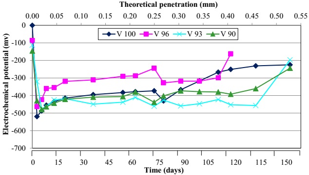
Figure 3 Average corrosion potentials (moistened area), in terms of the theoretical penetration and time
Before taking the measurements, it was moistened for 2 days with the aforementioned NaCl 0.3% solution in weight, until reaching constant moisture; subsequently, a constant current density was applied through a galvanostat for the duration of the test. Under these conditions, the evolution of the corrosion potential was followed-up at various characteristic points of the beam (on the dry and humid areas, coinciding or not with the abutments). All the measurements were carried out by previously disconnecting the galvanostat, and the cement was moistened in the areas where the determinations would be subsequently carried out, such that the measurements of the potentials would stabilize quickly. This moistening process normally lasted a couple of hours.
The theoretical penetration of the attack on the bars was determined using the Faraday law (Alonso, 1998), assuming a uniform corrosion of the reinforcement; therefore, it could be said that the determined penetration is an average value and could be estimated through the following expression:
Where: x: depth of the attack [mm];
0.0116: conversion factor of the units;
icorr: density of the corrosion current [μA/cm2];
t: duration of the attack [years].
This average depth of attack on the bars is obtained through the corrosion speed represented by icorr, which is kept constant by the galvanostat.
3. Results and discussion
3.1 Characterization
Table 4 shows details on the results obtained from the characterization tests of the properties of the concrete.
Table 4 Characteristics of the concrete used on the tested beams
| Compression (MPa) | Indirect tensión (MPa) | Capillary suction capacity (g/m 2 ) | Capillary suction speed (g/m 2 .s 1/2 ) |
|---|---|---|---|
| 27.0 | 2.5 | 2.773 | 3.45 |
According to the experimentally obtained results, the capillary suction speed is below 4 g/m2 s1/2, the maximum value for the capillary suction speed allowed by the Argentinian standard (Instituto Argentino de Normalización y Certificación, 2005); thus, the concrete is adequate for the structures located in environments with the presence of chlorides.
3.2 Electrochemical follow-up
Figure 3 shows the electrochemical behavior of the reinforcement, where the evolution of the corrosion potentials was graphed, representing the average of the measurements obtained on 5 points located in the central area affected by corrosion on each of the 4 tested beams. There are two scales on the abscissa axis, one represented by the time passed since starting the test and, in the upper part of this figure, the theoretical penetration of the attack, which is an average value fixed with the Faraday law (Equation (1)), applied to the material losses in the reinforcement located in the central area of the beams.
It is worth noting that while the test was prolonged for approximately 160 days, when reaching 140 days, beam V96 reached the point of collapse (Figure 4) due to a significant reduction of the cross-section of its reinforcement, produced by the depth of the pitting caused by the corrosion. Whereas beam V100 broke at 160 days, at which time the tests were finalized. This indicates that the corrosive process as is known, affects the residual life of the structural element affected, but that pitting, in particular, can decrease it even more.

The electrochemical behavior analyzed in the four beams, through the follow-up of their corrosion potentials, showed that in the course of the first 5 days, since connecting the accelerated corrosion process, the minimum potential value was reached; the beams with less coating (V96 and V100) were the ones that completed their activation period first (with minimum potentials between -478 and -531 mV). Subsequently, an increase of these potentials can be observed that could be considered as a pseudo-passivation process that is accompanied by the generalization of cracking (see Figure 5), which was similar on all the beams. Although the potentials of the two beams with lower coating / reinforcement diameter ratio are somewhat higher than the other two, it could be said that these are more passivated due to allowing an easier entry for oxygen from the exterior. This process was also found in previous works carried out in this laboratory (Aveldaño, 2011; Aveldaño, 2013; Schierloh, 2001).
3.3 Follow-up of the cracking areas
It is known that in reinforced concrete structures subjected to flexion, when the stress in the tension area surpasses the resistance of the concrete, cracks are formed, this is denominated “flexural cracking”, and which are identifiable by their cross-section direction to the main reinforcement of the beam. This is inevitable, whether or not there are corrosion problems. Furthermore, if the reinforcement are undergoing corrosion the cracking area is aggravated, as when both effects are present there is cracking due to flexion and corrosion.
Due to the fact that the products of corrosion possess a greater volume than the material from which they are derived, they generate internal pressure that cause part of these products to fill the pores of the concrete and to exit to the exterior through the flexural cracks (if there are any). As the corrosion advances and with the saturation of the pores, the oxides produce tensions that, when they surpass the rupture tensile stress of the concrete, it cracks in a longitudinal direction. These are known as “cracks by corrosion”. It is necessary to clarify that the division between cracking by flexion and by corrosion is not a very well defined concept, given that as the corrosion process evolves the progress of both of them becomes interrelated-possibly mutually strengthening each other. This difference in the direction of the cracks is what allows them to be classified in such a fashion.
The presence of flexural cracks (when the load is of a sufficient magnitude as to create them) accelerates the penetration of oxygen, water, and chlorides towards the reinforcement, thus favoring the corrosion process of the same (contributing to the increase of the cracking areas due to corrosion). On the other hand, by decreasing the section of the bars due to corrosion, the internal balance of the section causes an increase in the number of flexural cracks. Furthermore, with the flexural cracks being an exit to the exterior, a part of the corrosion products can grow in thickness and longitude which could increase even more the areas with flexural cracks. That is to say, the total growth of cracking implies a decrease of the resistant section of the beam (due to the section decline of the reinforcement and of the mechanically useful section of the concrete), so that, in the case of there being loads close to the breaking loads of the element, it could lead to the collapse of the structure as was the case with beam V96 at 140 days into the test.
The cracks were measured from the moment the external loads were placed. Figure 5 shows the evolution of the total cracking areas in each beam; that is to say, those obtained from the sum of the flex cracking areas, plus the areas of cracking by corrosion (in the same direction as the main reinforcement of the beam). It is worth remembering that the so-called cracking area is the sum of the products of the longitude by the width of each crack.

As predicted, the start of the cracking by corrosion manifested later on the beams with greater coating. Beams V90 and V93 had a similar evolution of the total cracking area throughout the duration of the test, taking into account the degree of dispersion that normally appears in most experimental works; whereas beams V96 and V100 showed a differentiated behavior, with total cracking areas greater than those of the remaining beams, this is due to having a lower r/ ratio of the reinforcement. However, if the flexural cracking area is analyzed separately (Figure 6), it can be observed that beam V96 showed higher values than the rest. This can be clearly observed with the state this beam reached, in which the deterioration by corruption presented itself to a greater extent in the area of the flexural cracks, whereas the rest of the beams showed a more generalized cracking. Evidently, this greater initial cracking due to flexion was a significant means of entry for the chlorides that reached all the way to the reinforcement, with beam V96 showing the largest total cracking area s (Figure 5) during the first 30 days of the test, after which their behavior was within the expected.

This behavior observed in beam V96 explains its collapse prior to that of beam V100. However, this evidences the influence of the lesser r/ ratio of beam V100, which, having the least flexural cracking during almost the entirety of the test, presented greater cracking by corrosion than the rest; as well as the importance that flexural cracking has in the deterioration of a structure subjected to corrosion, as is the case of beam V96.
In this work, we analyze the behavior of beams with a different r/ϕ ratio of their reinforcement, which are subjected to the same stress generated by external loads, in light of a corrosion process. A comparison can be made on the observed evolution of the cracking of the coating, with that obtained in other works carried out by the same research group (Moro, 2012) on beams made with concretes of similar qualities as the ones in this work, elaborated with or without recycled concrete aggregates and subjected to the same corrosive process, but without the application of external loads. In this case, the standard beam (without recycled aggregate) has a r/ ϕ ratio of 2.4 and is, therefore, comparable with beam V100 of this work. By carrying out a regression analysis of the total cracking areas in both beams, it can be observed that the slope is greater in V100 (y = 0.074 x -0.9502) than in the standard beam without external loads (y = 0.068 x -0.7688). This is due to the fact that the tensile stress in the bars of V100 causes flexural cracks, which facilitate the entry of aggressive agents from the exterior, causing an acceleration of the corrosion process.
It can be observed in Figure 7 that the appearance of the first visible cracks due to corrosion is delayed (the average depth of the attack is proportional to the time, expression (1)) as the thickness of the coating increases (greater r/ϕ ratio). The increase in the thickness of the coating causes a delay in the appearance of the first cracks due to corrosion (Figure 7), as well as slowing their evolution (see Figure 5) due to the fact that the aggressive external elements (chlorides, oxygen, and water) take longer to reach the reinforcement. This situation, in the case of the tensile reinforcement with lower r/ϕ ratios, is worrying due to the fact that this greater depth of attack on the bars, with less external symptoms (cracking), encloses a significant risk because it decreases the warning time in case of a structural collapse-more worrying still if there are chlorides that cause pitting. In Figure 7, a point corresponding to the standard beam (without external loads and a r/ϕ ratio = 2.4) of the aforementioned work (Moro, 2012) was incorporated, where it can be observed that a greater depth of attack is necessary for the appearance of the first visible cracks.
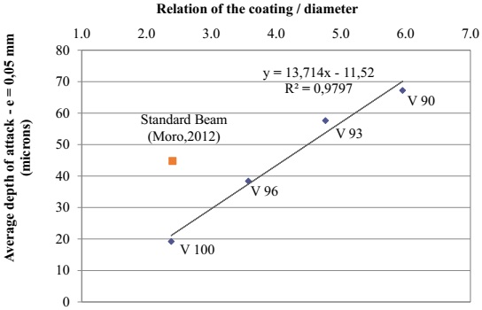
Figure 7 Relation between the average depth of attack on the reinforcement that produced the first visible crack (e = 0.05 mm) due to corrosion, and the relation of the coating / diameter of the bar.
The equation in Figure 7 obtained through a regression analysis (y = a + b x) can be compared with the one obtained in other researches (Alonso, 1998) where concretes made with water/cement ratios between 0.52 and 0.65 were used, while the rest of the test conditions are similar, among which the following stand out: a slightly broader variance range of the coating/diameter ratio than the one adopted in this paper, in both works the abutments were placed, and the same current intensity was utilized. The results achieved in the cited work were: a = 7.53 and b = 9.32, with R2 = 0.92. The slope of this line is much lower than the one obtained in this work (a= 13.71), therefore, it could be said that in structures subjected to external laws, the degradation generated by the corrosion of its reinforcement is accelerated, even for cements made with a water/cement ratio somewhat lower to that of the reference.
Once the test was finalized, the reinforcement was uncovered by removing the coating. In the visual inspection of the same, it could be observed that, due to the action of the chlorides (in spite of the low concentration adopted), the corrosion on the bars was, in general, not uniform. Rather, some areas of localized corrosion (pitting) could be observed, with no particular pattern. However, in some cases more pitting was found in areas close to the flexural cracks, as was the case of beam V96, in which the collapse section coincided with a flexural crack.
3.4 Follow-up of the maximum cracking width
Figure 8 shows the variation of the maximum cracking width in terms of time. It can be observed that the maximum cracking width, during the greater part of the test, was superior on beam V96 due to the influence of the flexural cracking. No great differences were observed in the evolution of the rest of the beams, which was due to the fact that the distribution of the cracking was developed differently on each beam, whether in a more generalized or localized manner, without generating evident differences between the different samples tested.

If the evolution of the maximum cracking width is compared with that of the cracking areas (Figure 5), it can be observed that the latter are a more representative indicator of the general evolution of the deterioration, due to the fact that it is common for the maximum width to vary in its location on the beam throughout the corrosion process. Furthermore, it tends to evolve in jumps in terms of the emergence of new cracks that cause the redistribution of the internal stress in the coating. For example, Figure 8 shows that beam V90 has the most cracking between days 40 and 90, when in reality it ought to be the one with the lesser values. This situation was also found in other works (Aveldaño, 2009; Aveldaño, 2013). Nevertheless, this figure is included due to the fact that it is common to introduce limitations on the maximum width of the cracks in the standards, and therefore it is used as a reference in many international bibliographies. It is worth noting that it would be necessary to carry out research to standardize the cracking area, so that valid comparisons between various deteriorated beams could be carried out, for example, in terms of the length of the affected element or the length of the corroded area, to later establish representative deterioration indicators and then limit it.
4. Conclusions
In this experimental work, it was found that the deterioration of beams exposed to external loads, due to the corrosion of its reinforcement, was greater than if said loads were not present and that the thickness of the coating influences this process; all of which affects the residual life and the bearing capacity of the affected structure. In particular, it was proven that:
In loaded beams with tensile reinforcement affected by accelerated corrosion, as the concrete coating / diameter of the reinforcement increases the longer it took for the first cracks to appear due to corrosion and their evolution became slower, evidencing the total cracking areas. The protection effect generated by greater coating makes the aggressive elements that come from the exterior (chlorides, oxygen, water) to require more time to reach the reinforcement, reducing the speed of the process;
The cracks of the concrete coating, caused by the flexion produced by external loads, favored the increase of cracking due to the corrosion of the reinforcement, thus increasing the total cracking and, therefore, influencing the subsequent degradation of the structure.
From a practical point of view, the aforementioned conclusions allow us to determine that in loaded reinforced concrete structures located in aggressive environments, it is worth it to decrease flexural cracking caused by the service loads as much as possible; as well as increase the ratio of the coating / diameter of the reinforcement in order to decrease the effects of corrosion in the same.
5. Acknowledgements
The authors would like to thank Ph.D. Carla Priano, engineer Lilia Señas, and the technicians J.P. Gorordo of the Laboratory of Structural Models and D. Smith of the Laboratory of Material Study and Testing, U.N.S., for their collaboration in the development of the tests. Furthermore, we thank the General Ministry of Science and Technology and the Engineering department of the Universidad Nacional del Sur for their financial and institutional support in the realization of these researches.
REFERENCES
Almusallam, A. A., Al-Gahtani, A. S., Aziz, A. R. (1996), “Effect of reinforcement corrosion on bond strength”, Construction and Building Materials, V. 10, No. 2, pp. 123-129. [ Links ]
Alonso, M. C., Andrade, C., Rodríguez, J., Diez, J. M. (1998), “Factors controlling cracking in concrete affected by reinforcement corrosion”, Materials and Structures, Nr. 31, pp. 435-445. [ Links ]
Alonso, M. C., Andrade, M. C., Rodríguez, J., Casal, J., García, M. (1994), “Evaluación experimental de la fisuración del hormigón producida por la corrosión de las armaduras”, Hormigón y Acero, No. 194, pp. 29-42. [ Links ]
Al-Sulaimani, J., Kaleemullah, M., Basunbul, I. A., Rasheeduzafar (1990), “Influence on corrosion and cracking on bond behaviour and strength of reinforced concrete members”, ACI Structural Journal, V. 87, Nr 2, pp. 220-231. [ Links ]
American Society for Testing and Materials: ASTM C876, “Standard test method for half-cell potential of reinforcing steel in concrete”, Philadelphia, U.S.A, (1980). [ Links ]
Andrade, M. C., Alonso, M. C., Molina, F. J. (1993), “Cover cracking as a function of bar corrosion: Part I - Experimental test”, Materials and Structures, Nr. 26, pp. 453-464. [ Links ]
Aveldaño, R. R., Ortega, N. F. (2009), “Influence of reinforcement distribution in the corrosive process of reinforced concrete beams”, Magazine of Concrete Research, Thomas Telford, V. 61, Nr. 3, pp. 213-220. [ Links ]
Aveldaño, R. R., Ortega, N. F. (2011),“Characterization of Concrete Cracking due to Corrosion of Reinforcements in Different Environments”, Construction and Building Materials,V.25, pp.630-37. [ Links ]
Aveldaño, R. R., Ortega, N. F. (2013), “Behavior of concrete elements subjected to corrosion in their compressed or tensed reinforcement”, Construction and Building Materials, Nr. 38, pp. 822-828. [ Links ]
Calabrese, L., Campanella, G., Proverbio, E. (2013), “Identification of corrosion mechanisms by univariate and multivariate statistical analysis during long term acoustic emission monitoring on a pre-stressed concrete beam”, Corrosion Science, V. 73, pp. 161-171. [ Links ]
Elfergani, H. A., Rhys, P., Holford, K. M. (2013), “Damage assessment of corrosion in prestressed concrete by acoustic emission”, Construction and Building Materials, V. 40, pp. 925-933. [ Links ]
Fumin, L., Yingshu, Y., Chun-Qing, L. (2011), “Corrosion propagation of prestressing steel strands in concrete subject to chloride attack”, Construction and Building Materials, V. 25, Nr.10, pp. 3878-3885. [ Links ]
Hariche, L., Ballim, Y., Bouhicha, M. Kenai, S. (2012), “Effects of reinforcement configuration and sustained load on the behaviour of reinforced concrete beams affected by reinforcing steel corrosion”, Cement and Concrete Composites, V. 34, Nr. 10, pp. 1202-1209. [ Links ]
Instituto Argentino de Normalización y Certificación “IRAM 1627: “Agregados. Granulometría de los agregados para hormigón”, Buenos Aires, (1997). [ Links ]
Instituto Argentino de Racionalización de Materiales - Instituto Argentino de Siderurgia, Norma U 500-528: “Barras de acero conformadas de dureza natural, para armadura en estructuras de hormigón”, Buenos Aires, (1989). [ Links ]
Instituto Argentino de Normalización y Certificación IRAM 1871: “Método de ensayo para determinar la capacidad y la velocidad de succión capilar de agua del hormigón endurecido”, Buenos Aires, (2005). [ Links ]
Instituto Argentino de Normalización y Certificación IRAM 1546: “Hormigón de cemento portland. Método de ensayo de compresión”, Buenos Aires, (1992). [ Links ]
Instituto Argentino de Normalización y Certificación IRAM 1658: Hormigón. “Método de ensayo de tracción simple por compresión diametral”, Buenos Aires, (1995). [ Links ]
Instituto Argentino de Normalización y Certificación IRAM 1534: “Hormigón de cemento portland. Preparación y curado de probetas para ensayos en laboratorio”, Buenos Aires, (1985). [ Links ]
Malumbela, G., Moyo, P., Alexander, M., (2009), “Behaviour of RC beams under sustained service loads”, Construction and Building Materials, V. 23, Nr. 11, pp. 3346-3351. [ Links ]
Melchers, R. (2001), “Assessment of existing structures, approaches and research needs”, Journal of Structural Engineering, ASCE, pp. 406-411. [ Links ]
Moro, J. M., Meneses, R. S., Ortega, N. F., Aveldaño, R.R., Señas, L., Priano C. V. (2012), “Corrosión de Armaduras en Estructuras de Hormigón Reciclado con Tratamientos Previos”, CINPAR 2012, VIII Congreso Internacional sobre Patología y Recuperación de Estructuras, 11 páginas. [ Links ]
Ortega, N. F., Alonso, M. C., Andrade, M. C., López, C. (2001), “Análisis de la fisuración ocasionada por la corrosión de las armaduras activas de elementos pretensados”, Coloquia, Madrid. [ Links ]
Peralta, M. H., Rivas, I. E., Ortega, N. F. (2006), “Análisis Numérico de la Fisuración Superficial de Estructuras de Hormigón Armado por Efecto de la Corrosión”, Informes de la Construcción, V. 58, No. 501, pp. 51-58. [ Links ]
Rodríguez, J., Ortega, L. M., Casal, J., Vidal, M. A. (1993), “Disminución de la adherencia entre hormigón y barras corrugadas debido a la corrosión”, Hormigón y Acero, No 189, pp. 49-65. [ Links ]
Rodríguez, J., Ortega, L. M., García, A. M. (1993), “Medida de la velocidad de corrosión de las armaduras en estructuras de hormigón, mediante un equipo desarrollado dentro del proyecto Eureka EU 401”, Hormigón y Acero, No. 189, pp. 79-91. [ Links ]
Rodríguez, J., Ortega Basagoiti, L. M., Casal, J., Diez, J. M. (1996), “Comportamiento estructural de vigas de hormigón con armaduras corroídas”, Hormigón y Acero, No. 200, pp.113-131. [ Links ]
Rodríguez, J., Ortega Basagoiti, L. M., Casal, J., Diez, J. M. (1998), “La corrosión de armaduras y la vida residual de las estructuras de hormigón”, Hormigón y Acero, No. 208, pp. 63-78. [ Links ]
Schierloh, M. I. (2003)., “Corrosión de armaduras. Características que debe tener el hormigón para aumentar la protección”, Tesis de Magíster en Ingeniería, Departamento de Ingeniería, Universidad Nacional del Sur, Director de Tesis: Ortega N.F. [ Links ]
Schierloh, M. I., Ortega N. F., Señas L. N. (2001), “Relación entre Algunas Propiedades del Hormigón del Recubrimiento y el Proceso Corrosivo de las Armaduras”, 14° Reunión de Asociación Argentina de Tecnología del Hormigón, pp. 125-132. [ Links ]
Torres-Acosta, A. A., Navarro-Gutierrez, S., Terán-Guillén, J. (2007), “Residual flexure capacity of corroded reinforced concrete beams”, Engineering Structures, V. 29, Nr. 6, pp. 1145-1152. [ Links ]
Tuutti, K. (1982); “Corrosion of steel in concrete”, Swedish Cement and Concrete Institute (CIB) pp. 4-82, Stockholm, Sweden. [ Links ]
Yu, L., François, R., Dang, V. H., L'Hostis, V., Gagné, R., “Development of chloride-induced corrosion in pre-cracked RC beams under sustained loading: Effect of load-induced cracks, concrete cover, and exposure conditions”, Cement & Concrete Research, Nº67, 2015, pp.246-258. [ Links ]
Received: February 02, 2016; Accepted: April 11, 2016
 Este es un artículo publicado en acceso abierto bajo una licencia Creative Commons
