


 nueva página del texto (beta)
 Inglés (pdf)
 Artículo en XML
 Referencias del artículo
 Enviar artículo por email
 Citado por SciELO
  Similares en
SciELO
Similares en
SciELO 
 Permalink
1. Introduction
From the seminal work by Pecora and Carroll [1] on synchronization in experiments of electrical circuits, numerous works on this theme have been published [2]. In particular, four systems of low dimensionality have been extensively studied in a systematic way to understand the chaotic behavior and the synchronization; namely, Lorenz and Rössler systems and Duffing and van der Pol oscillators. We can mention, for instance, that it has been observed that two coupled van der Pol oscillators show a rich fractal structure whenever they interact [3]. Other systems based on the forced Duffing oscillator [4-6], as well as the coupled Lorenz or Rössler systems [7,8] have also been analyzed. The dynamics of coupled nonlinear oscillators, identical or not, with the same kind of attractors is still under scrutiny. Nevertheless, the dynamics of these systems with different kind of attractors is hardly been studied and it could give rise to important information. In fact, a system of coupled oscillators could model real systems in nature [8], such as hysteresis or resonant phenomena like the found in biological or electromechanical systems.
As far as the coupling between two different oscillators is concerned, there exist three distinct basic schemes of coupling that have been used in the literature, namely: gyroscopic (coupling through acceleration), dissipative (coupling through speed) and elastic (coupling through solution) [9-15]. Among the diverse ways of coupling the van der Pol and Duffing systems, the most common are the elastic and dissipative ones [13-17]. However, up to our knowledge, there are no previous studies on how to mix different couplings between distinct dynamical systems. In this work, it is proposed to combine elastic and dissipative couplings into a dynamical system in order to achieve synchronization.
Previous studies on synchronization are only based on using a single type of coupling. There exist several proposals for synchronizing two dynamical systems, such as the adaptive method, the feedback method [2] and, more recently, the fuzzy control [18] or the bang-bang method [19,20]. One of the most used ways to check whether two dynamical systems are synchronized is through the error function [2] or equivalent by means of a straight line in the plane of the corresponding variables.
The study of synchronization is mainly motivated by the fact that the phenomenon is observed in many coupled systems ranging from biological to physical systems. Synchronization occurs in many natural and technological systems, from cardiac pacemaker cells to coupled lasers [21,22]. Therefore, understanding the mutual interactions of coupled oscillators and obtaining consensus and phase locking among corresponding states of these oscillators leading to their synchronization is a key challenge. Thus, the comprehension of how individual rhythm of oscillation in the systems adjust with each other such that the coupled systems oscillate with a common frequency, is yet a problem that needs attention [23]. There are several schemes to enforce synchronization on a pair of systems: The master-slave, the mutual, or the adaptive, just to mention a few [24,25].
Chaos in electrical circuits is a topic of current interest from both theoretical and experimental point of view. The synchronization of a chaotic system is of interest due to its applications in encrypting signals and in secure communication systems, in both stable and chaotic regions. The Chua circuit is the simplest electronic circuit exhibiting chaos, and many well-known bifurcation phenomena, as verified from numerous laboratory experiments, computer simulations, and rigorous mathematical analysis. This circuit consists of an inductor, a resistor, two capacitors, and a nonlinear element called Chua diode [26, 27]. The Chua diode provides the non-linearity to the circuit, the nonlinear part is represented a three-segmented piecewise linear function.
In a work by González et al., (GEA) [28] the chaotic dynamics was analyzed by means of circuits with nonlinear parts performed by three-segmented piecewise linear functions. This nonlinear function is different from the corresponding provided by the Chua diode, and it is generated by saturation of the operational amplifiers. The system presents a double-scroll located around the break point of the nonlinear function. We will be using this system for the subsequent analysis. The subject in this work is twofold: to propose a different way of coupling distinct low-dimensional dynamical systems and introduce a way of measuring the degree of synchronization through bifurcation diagrams varying the coupling constant between the coupled systems. To this end, we employ a modified system of that given by the GEA circuit, where the nonlinear function is used in the two equations describing the dynamical system. The modified circuit is coupled to the GEA circuit to illustrate the synchronization between the systems in terms of the bifurcations diagrams.
An outline of this paper is as follows. In Sec. 2, it is briefly studied the main features of the GEA circuit. In Sec. 3, it is presented a modified GEA circuit that will be used to study the synchronization. Section 4 is devoted to exemplify the proposed way of synchronization trough the use of bifurcation diagrams. In Sec. 5, some final remarks and an outlook are presented.
2. Forced nonlinear circuit
The GEA circuit [28] is shown in Fig. 1a). By applying Kirchoff’s laws and using as variables the voltage u c , on the capacitor, and the current in the inductance i L , it is found that the equations governing the dynamics are

where v = v(u c ) represents the nonlinear function, which is given by
and its behavior is displayed in Fig. 1b).
The external forcing is assumed periodic given by bsin(ωt), where b is the amplitude. This signal is injected into the node F (see Fig. 1a)). In the setup of the circuit it is used the components R 1 = 200 kΩ (potentiometer), R 2 = R 4 = R 5 = R 6 = R 7 = 100 kΩ, R 3 = 1 kΩ (potentiometer), R L = 1 kΩ (potentiometer), C = 100 nF, L = 100 mH, Z 1 ,Z 2 are Zener diodes of 4.7 V, A 1 and A 2 are operational amplifiers (OA’s) LM741CN. These OA’s are driven at ±12 V. The OA A 2 is used as unity gain, being their drivers the forcing and the output of the voltage limiter. The output signal from A 2 is used as a feedback through a RCL circuit as low-pass and it is injected into A 1 which acts as an inverse gain. The gain G 1 is
The nonlinear function is due to the voltage limiter connected to the output of the OA A 1, performed by the resistor R 3 and the Zenner diodes Z 1 y Z 2 at 4.7 V. The maximum output voltage of the limiter is V Z = 5.3 V, since the the Zenner diodes operate as regulators. In Fig. 1b) is displayed the voltage of the limiter as function of the voltage u c on the capacitor C, for the case in which R 3 is adjusted very small compared with respect to the others resistors in the circuit.
To carry out the dynamical analysis of the GEA circuit, it results useful working with a mathematical model with the minimum of parameters demanding the model describes the same dynamics. For this propose, it is convenient transform in Eqs. (1) and (2) into a set of dimensionless equations by means of the following change of variables. For the dynamical variables, we have:
while for the constants
In this manner, the dynamical system becomes
where the over dot stands for the derivative with respect to the τ variable and f(x) represents the dimensionless nonlinear function in Eq. (2) given by
An analysis of Eq. (4) considering it as an autonomous system (by setting γ 1 = 0) shows that the system has three fixed points, from which two are stable located at (±G 1 ,0). Notice that the stable points exist if G 1 > 1. The third fixed point is located at the origin and acts as a saddle point.
To study the evolution of the GEA circuit, we perform numerical simulations using Eq. (4), with the following values for the parameters: α 1 = 0.09,Ω1 = 0.254,γ 1 = 1.14 and G 1 = 3.25. In Fig. 2a) it is shown the resulting trajectory in the phase space, which is a double-scroll. Figure 2b) shows the bifurcation diagram with α 1 as a parameter of control, which vary from 0.04 to 0.13 with initial conditions x(0) = 0.0 and y(0) = 0.5. Looking at the bifurcation diagram, is to see some ranges where the double-scroll structure is maintained.

3. Proposed nonlinear oscillator
Taking into account the GEA circuit previously described, we propose a nonlinear oscillator based on the same nonlinear function of this circuit. The difference of the resulting nonlinear oscillator consists in the fact that it has two nonlinear piecewise functions with different amplitudes and slopes corresponding to ε 1 g(u) and ε 2 g(u) functions (see Eq. (6)), which give rise to an oscillator with a more complex dynamics. The advantage of the two piecewise functions, when we implement the synchronization with the GEA circuit, consists in that the system now comprises of three piecewise functions with different amplitudes and slopes, namely: ε 1 g(u), ε 2 g(u) and α 1 f(x). The schematic diagram of the new circuit is shown in Fig. 3a). The dynamics is governed by the equations:

being the nonlinear function g(u), the same as the given in Eq. (5), but, in general, with different gain G 2:
We calculate the fixed points of (6), by considering the system as an autonomous one (by setting γ 2 = 0). The resulting sulting system presents three fixed points, from which two of them are stable and located at (±(ε 2 G 2 /α 2),±ε 1 G 2). Again, these points exist if G 2 > 1. Again, these points exist if G 2 > 1. The third fixed point is located at the origin and, as in the case of the GEA system, it is a saddle point.
In order to study the dynamical behavior of the proposed system, we perform numerical simulations using the following values for the parameters:
With these particular values, the system presents the solution presented in Fig. 3b), which is also a double-scroll attractor.
4. Synchronization of the nonlinear oscillators
In this section we propose a different manner of coupling chaotic systems to reach the unidirectional coupling, this is done for the nonlinear oscillators previously studied. Let us stress that the synchronization between coupled forced systems has been hardly studied [29, 30], because there are few low-dimensional chaotic systems known in the literature. Three of the most studied oscillators are the Duffing, van der Pol, and Rayleigh, since much of the dynamical features embedded in the physical systems can be realized in these systems [31-33]. One important implication is that a two-dimensional continuous dynamical system cannot give rise to a strange attractor. In particular, chaotic behavior only arise in continuous dynamical systems whose phase space has three or more dimensions. Most of the research on synchronization is based on autonomous systems that satisfy the Poincaré-Bendixson theorem.
The dynamics of the resulting coupled system is governed by
where the nonlinear functions f(x) and g(u) are given in Eqs. (5) and (7), respectively, and we use t instead of the τ parameter. Firstly, notice that the coupling in Eq. (8) is between different dynamical systems. Secondly, the systems in question are under an external forcing. Finally, and more importantly, is that the way of coupling the circuits in this work is new: instead of using one coupling constant, we use two, namely: K and H. This way of coupling has the advantage that allows to choose one of the systems as the master and the other as the slave or conversely by putting one of the constants K or H to zero. For K = H = 0 case, both oscillators decouple. The coupling employed in the system is a kind of linear feedback that can be seen as a perturbation for each oscillator proportional to the difference of the position (elastic coupling) and the velocity (dissipative coupling). Let the system evolve toward a chaotic region. We will study the dynamical evolution.
In first place, we set H = 0 and take K as the parameter to be varied. In this case, we have an unidirectional coupling because the proposed nonlinear circuit acts as the master while the GEA circuit will act as slave. The synchronization scheme introduced here is indeed a modified version of the classical master-slave synchronization. The key difference is that we have two couplings, the elastic one corresponds to K(u − x), and the dissipative one represented by K(v − y). In this instance the synchronization scheme is given by
In general, the synchronization problem reduces to finding a suitable value of the coupling strength K, (denoted by K*) being in the range K ≥ K* > 0, such that the master and slave systems synchronize. Thus, for a coupling strength K*, when the synchronization is reached, the error function goes to zero:
For certain systems, it is not possible to achieve synchronization when using the classic master-slave system. Specifically, there are cases for which it is impossible to find a value of coupling strength K* such that the systems achieve the synchronization [34]. This work elaborates on a possible solution for the problem above described. In particular, we consider a modified master-slave scheme which may induce synchronization even in cases where the classical master-slave synchronization fails.
The bifurcation diagrams are obtained through the solutions of x(t), y(t), u(t), v(t), | u(t) − x(t) | and |v(t) − y(t) |, taking K as a control parameter which is varied in very small steps from 0 to 50. As it can be observed from Figs. 4a) and b), the bifurcation diagrams for the variables x(t) and u(t) coincide in most part of the range of the parameter K. This indicates that the systems are synchronized, except for values of K close to zero, for which the systems are partially synchronized. Notice that the coincidence is not only in the magnitude of the variables but also in the number of curves. The very same coincidence occurs in the bifurcation diagrams for the variables y(t) and v(t) shown in Figs. 4c) and d). As before, the coincidence is better for larger values of K. This means that the systems are coupled unidirectionally. In addition, it is observed that the synchronization is realized in both the x−u and the y−v channels. In the mentioned cases the synchronization is complete. However, in practical applications, such as the sending information, the channel x − u has a larger range of control [2].
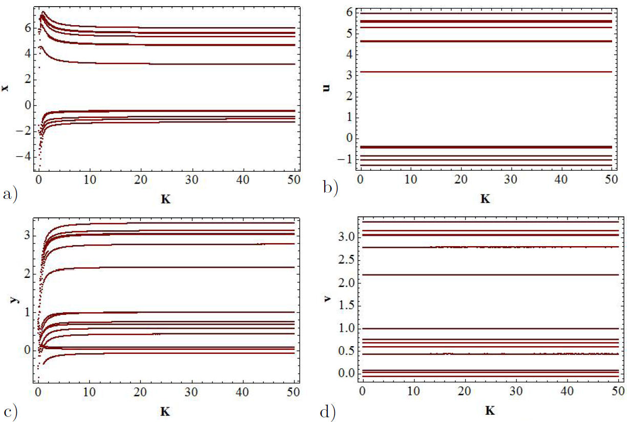
FIGURE 4 Bifurcation diagrams, the control parameter is K. a) The solution x(t) represents the function of GEA oscillator. b) The function u(t) is for the proposed oscillator. In c) and d) the bifurcations diagrams for the y and v variables are shown.
As it is well known, one of the most used ways of proving whether two dynamical systems are synchronized is through the error function. The bifurcation diagrams for the error functions |u(t) − x(t)| and |v(t) − y(t)| allow us to find the range of values of K for which the synchronization of the x − u and u − y channels take place, as it can be observed from Figs. 5a) and b).
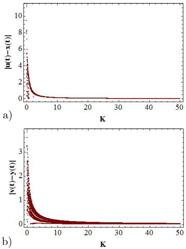
FIGURE 5 Bifurcation diagrams for the error signals: in a) is presented |u(t) − x(t)|, and in b) the |v(t) − y(t)| function.
In order to corroborate the fact that the level of synchronization can be analyzed through bifurcation diagrams, let us consider the graphs shown in Fig. 6, that were obtained by taking the value K = 50. For this value the master system (the proposed circuit) is in the regime of a double-scroll attractor. From this figure, it can be appreciated that in channels x − u and y − v the dynamics of the GEA oscillator is controlled by the proposed oscillator and that the systems in these channels, according to in Figs. 6c) and d), are synchronized.
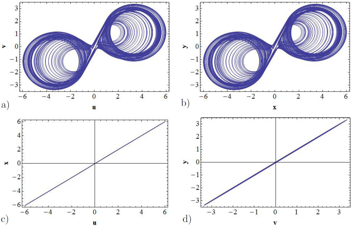
FIGURE 6 Unidirectional coupling, by using the parameter control K = 50. In a) it is displayed the double-scroll attractor for the proposed nonlinear oscillator. In b) is presented the corresponding attractor for the GEA circuit, while in c) and d) are shown the synchronization signals in the x − u and y − v channels.
Let us now take K = 0 in Eq. (8) and consider as control variable the coupling H. In this instance, we have an unidirectional coupling where the GEA oscillator acts as the master system and the proposed oscillator as the slave.
The elastic coupling corresponds to H(x − u), and the dissipative one to H(y−v). As before, the synchronization problem reduces to look for a suitable value of coupling strength (denoted in this case as H*), with H ≥ H* > 0 such that the master and slave systems synchronize. For this case the error functions read as
Again, the bifurcation diagrams, with H as control parameter, are obtained through the functions x(t), y(t), u(t), v(t), |u(t)−x(t)| and |v(t)−y(t)| by varying H in small steps along the interval from 0 to 50.
As it can be observed in Figs. 7a) and b), the bifurcation diagrams for the x(t) and u(t) variables, which are functions of H, coincide as the intensity of coupling H is increased. These functions agree not only in the respective values of the functions but also in the number of lines. Nevertheless, the bifurcation diagrams for the y(t) and v(t) functions coincide partially, as it can be appreciated from Figs. 7c) and d). The coincidence is better as the intensity of the coupling increases, being practically the same functions for rather larger values of H. Notice that, in this case, the number of lines generated does not coincide. This means that there exists only partial synchronization. The bifurcation diagrams of the error functions |u(t) − x(t)| and |v(t) − y(t)| allow us to find the range of values of H for which the synchronization of the x − u and y − v channels take place, as it can be observed from Figs. 8a) and b). Figure 8b) we can see that the error function is not zero, which implies that there is only partial synchronization in the y − v channel.
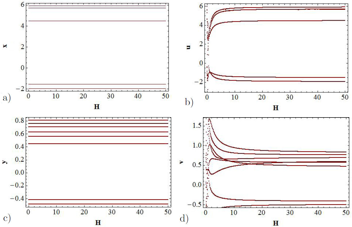
FIGURE 7 Bifurcation diagrams. The control parameter in this case is H. a) The function x(t) represents to the GEA nonlinear oscillator. b) The function u(t) represents proposed nonlinear oscillator. In c) and d) the bifurcations diagrams for the y and v channels are shown.
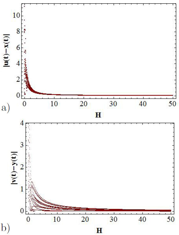
FIGURE 8 Bifurcation diagrams for the error functions as a function of H parameter. In a) it is shown |u(t) − x(t)|, while b) shows the |v(t) − y(t)| function.
In order to corroborate that in the x − u channel it is reached the complete synchronization, while in the y − v channel there is only partial synchronization, let us observe the double-scroll attractors for the GEA circuit and for the proposed circuit in Figs. 9a) and b) respectively. In Figs. 9c) and d) are displayed the corresponding error functions. Let us mention that for plotting these figures we have taken the value H = 50. Thus, we conclude that it is more simple to reach synchronization by coupling the position than coupling of the velocities.
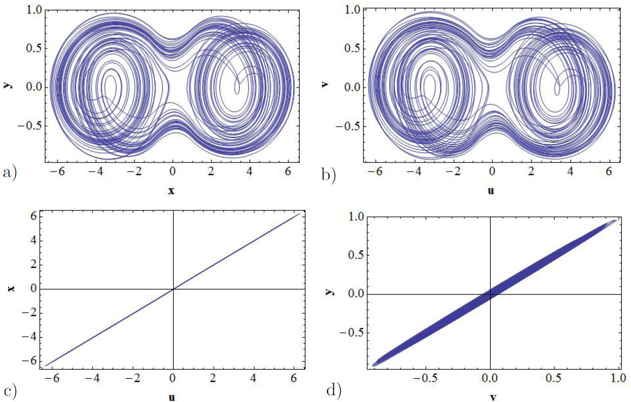
FIGURE 9 Unidirectional coupling for the value H = 50. In a) it is shown the double-scroll attractor generated by the GEA circuit and in b) it is shown the corresponding attractor for the proposed circuit. In c) and d) the corresponding synchronization signals of the x − u and the y − v channels are shown respectively.
5. Final remarks and outlook
The most common and used way of synchronization between nonlinear systems is through the analysis of the phase space in the channels to be studied by demanding that the corresponding error functions to be zero. In this work, a modified version of the classical master-slave synchronization scheme has been proposed, in which the synchronization can be induced in the slave system by using a first order dynamic controller. Therefore, in the proposed scheme, the master and slave systems have an indirect interaction, through the elastic and dissipative couplings. The study of synchronization through the bifurcation diagrams for the x(t), y(t), u(t), v(t), |u(t) − x(t)| and |v(t) − y(t)| functions, taking as a parameter the coupling constants, helps to identify the regions where there is a complete or a partial synchronization. To do that, we introduced a nonlinear oscillator based on the GEA oscillator and used two coupling constants instead of only one. We coupled both oscillators unidirectionally and identified the channels where it is obtained total synchronization. Whenever the proposed oscillator acts as the master there exists total synchronization in the x − u and y − v channels. Nevertheless, when the GEA nonlinear oscillator acts as the master, there only exists partial synchronization in the x − u channel. One important feature to be remarked is the fact that the synchronization is favored for rather larger values of the coupling. Accordingly, the employ of bifurcation diagrams to analyze the level of synchronization could be of worth. Up to our knowledge, this way of study the synchronization, although rather graphical, has not been previously reported in the literature. Finally, we will like to comment that this way of synchronize has been carried out successfully for others nonlinear systems. Moreover, with the way of coupling the dynamical systems, we have achieved bidirectional coupling. Our results will be presented in a separated communication. A potential application of the results presented here is in secure communication systems. For example, it is well known that a message can be encrypted at the transmitter by mixing it with a chaotic signal, in order to decode the message the receiver should be synchronized with the transmitter.
Finally, let us stress that the way of coupling presented in this work can also useful in systems such as the classical master-slave where it is used only one coupling and the synchronization cannot be reached. Further study in this direction will presented in future papers.

