


 nueva página del texto (beta)
 Inglés (pdf)
 Artículo en XML
 Referencias del artículo
 Enviar artículo por email
 Citado por SciELO
  Similares en
SciELO
Similares en
SciELO 
 Permalink
1 Introduction
Due to the dark condition of the road, driving at night is really tough. Other vehicles are also not visible properly. In the dark condition of the road overtaking is quite impossible.
Sometimes vehicle in front in the same direction, has a very slow speed. Therefore, we also had to move with very slow speed behind the slow vehicle. It wastes valuable time for a fast vehicle to run behind a slow vehicle unnecessarily.
Overtaking with rash driving in dark road increase the probability of road accidents. It is observed that, out of all road-accidental deaths, 44% are due to rash driving, which is likely due to over speed, overtaking, and driver's wrong prediction about other vehicles [1].
Almost 45% of traffic accidents happen at night. The maximum number of road accidents (18.6 %) recorded between 6:00 pm and 9:00 pm [2].
Real-time estimation of vehicle-to-vehicle distance followed by relative and actual speed from another moving vehicle is really difficult at night. Objects and vehicles are not visible properly, only taillights and headlights are visible at night (see figure 1).

The estimation becomes more difficult in the presence of oncoming vehicle from the reverse direction. By watching only the headlights of an oncoming vehicle, it is not possible to estimate a safe driving trajectory. Therefore, it is very tough to decide whether an overtake is safe or risky.
Few researchers tried to solve the problem of uncertainty while making a decision of overtaking during day time. The decision of overtaking whether it is safe or risky is comparatively easier during day time when the road has a clear view of sunlight. However, overtaking during the night is really difficult.
This condition creates confusion for a driver and if the driver takes the risk of overtaking, then it causes a pathetic road accident in maximum cases. It is not possible to understand the distance and speed of the oncoming vehicle from a far distance at night. This situation is very dangerous because by watching only headlights of an oncoming vehicle, it is not possible to estimate the gap between vehicles and acceleration required for safe overtaking. The primary contributions of this paper are summarized as follows:
— The proposed method can estimate vehicle-to-vehicle distance, relative and actual speed of any vehicle from a moving test vehicle at night.
— The approach is designed for complex traffic situations where oncoming and ongoing both vehicles are running on a two-lane road.
— The vision-based assistance is made by observing only the visual parameters of taillights and headlights.
— Sensitive vision-based parameters of headlights and taillights are used to estimate the exact distance and speed with actual and relative values.
— Parameters like road condition level, required speed and acceleration are used to take a safe overtaking decision for drivers.
— No high-cost sensors are used for estimations like state-of-the-art techniques. A low-cost 2D camera is used in the proposed method.
— The proposed approach aims to provide assistance in minimum processing time.
The rest of the article is structured as follows. Section 2 describes literature survey related to the proposed approach. Section 3 provides an ephemeral picture of the general overtaking maneuver. Section 4 presents the proposed approach. Section 5 represents an evaluation of real-time empirical performance. Lastly, Section 6 represents the conclusion and describes the next steps in future research.
2 Literature Survey
Few scholars attempted to estimate the distance and speed of vehicles on the road in real-time. However, most of the attempts are made in the daytime and used high-cost sensors in a fixed position. To our knowledge, no study is available to assist a driver in taking decisions for overtaking at night time. In this article, a novel and effective solution have been presented to assist a driver to take a perfect overtaking decision at night. Few studies of day time are discussed.
Great et al. [3] and Wicaksono et al. [4] used the Gaussian Mixture Model along with filtering techniques and post-processing steps to extract foreground image from recorded video. Finally, the location is determined in each frame to estimate the speed based on its distance between frames.
Hua et al. [5] combined modern deep learning with classic computer vision approaches to predict vehicle speed efficiently. The speeds of vehicles are estimated using a static camera from the corner point movement within the track associated with the vehicle.
Giannakeris et al. [6] introduced a fully automatic camera calibration algorithm to estimate the speed of vehicles.
Koyuncu et al. [7] detected speed of vehicles by using a simple camera and image processing software. The speed is calculated as the ratio of real distance covered by the camera field of view (FOV). Qi et al. [8] measured the distance between two vehicles based on the vehicle pose information by monocular vision.
Javadi et al. [9] presented a video-based speed estimation method of vehicles using the movement-pattern vector as an input variable.
Weber et al. [10] analyzed and discussed the influence of the road anomalies and the vehicle suspension for tracking and distance estimation of vehicles.
Kim et al. [11] estimated the distance of a vehicle driving in front by extracting the aggregated channel features of frames using a single black-box camera. Moazzam et al. [12] presented a vehicle speed determination method from video using the "boundary box" technique.
Bastos et al. [13] and Bell et al. [14] used Convolutional Neural Networks (CNNs) and the "You Only Look Once" (YOLO) algorithm to detect vehicles and their distances.
Liu et al. [15] introduced a lightweight network to amend the feature extraction layer of YOLOv3 to estimate the distance of vehicles.
Vakili et al. [16] and Ali et al. [17] presented a single view geometry-based relative distance estimation algorithm using a camera and the geometric information of the camera system.
Zaarane et al. [18] introduced an inter-vehicle distance estimation method for self-driving based on a camera view field angle using a stereo camera, installed behind the rear-view mirror of the host vehicle.
Few researchers attempted to solve the problem of overtaking decision for the two-lane road during day-time, are discussed here.
Milanés et al. [19], Naranjo [20] and Basjaruddin et al. [21] proposed a fuzzy logic based automatic overtaking system using artificial intelligence and computer vision.
Shamir [22] presented an overtaking maneuver method that provides a minimum trajectory for changing lane during overtaking. The overtaking trajectory depends on enough initial velocity, the minimum distance to cover and minimum time needed by explicit formulas.
Sezer [23] offered a new design to solve the overtaking problem for bi-directional roads using Markov Decision Procedure that works based on Mixed Observability.
Groza et al. [24] and Vieira et al. [25] used a warning alert for drivers during overtaking maneuvers. The system depends on vehicle-to-vehicle communication technologies based on a vehicular Adhoc network (VANETS) and multi-agent systems.
Yu et al. [26] and Ngai et al. [27] used reinforcement learning practices to solve the problem of cooperative overtaking.
Vasic et al. [28] presented an algorithm based on a sensor fusion technique and cooperative tracking to take an overtaking decision for intelligent vehicles that are connected with a network.
Patra et al. [29] introduced an ITS based overtaking assistance system for drivers that provides real-time live video streaming from the front vehicle. Even if the driver is unable to view the road view due to any blocked vehicle in the front, this system provides a clear vision of the road ahead.
Ghumman et al. [30] presented a novel overtaking approach by changing the lane for an autonomous vehicle based on the on-line trajectory-generation method.
Raghavan et al. [31] and Wang et al. [32] presented the solution of the classic car overtaking problem by a control algorithm which minimizes the probability of collision with cars.
Németh et al. [33] introduced an overtaking driver assistance system for autonomous vehicles using a hierarchical function.
Barmpounakis et al. [34] developed an unconventional overtaking pattern for drivers who use powered two-wheeler by using a decision tree that is meta-optimized.
Zhou et al. [35] introduced Gap Acceptance Based Safety Assessment of Autonomous Overtaking Function. Elleuch et al. [36] proposed numerous cooperative overtaking assistance systems based on Vehicular Ad hoc Networks (VANET) to prevent collisions.
3 General Overtaking Maneuver
A normal overtaking maneuver is usually used to cross a slower vehicle or a stationary vehicle present in the same lane. This process can be completed on bi-directional roads and also on the freeways, which is only one wide lane and vehicles run in both directions. An overtaking maneuver consists of three phases:
a) diverting from the actual lane,
b) driving forward in the attached adjacent lane until the overtaking vehicle has passed, and
c) returning to the actual lane (see figure 2(a)).
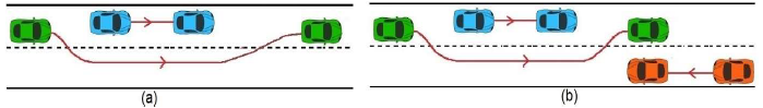
Fig. 2 Overtaking maneuver with new position of vehicle after overtake (a) Normal overtaking maneuver; (b) overtaking maneuver on difficult situation with another vehicle is coming from opposite direction
This three-phase overtaking maneuver is quite simple if we consider only one slow vehicle in front of the overtaking vehicle and there is no other vehicle in any direction. Whereas if there is another vehicle coming from the opposite direction (see figure 2(b)), then the decision of overtaking becomes difficult.
4 Proposed Approach
In this article, a novel overtaking assistance system is proposed for drivers. The proposed approach is completely vision-based and depends on the analysis of visual parameters of headlights and taillights at night.
This approach can help a driver to make perfect and safe decision of overtaking at night time under such a difficult situation where some other vehicle is coming from the opposite direction with a slow vehicle in the front. The overall framework is shown in figure 3.

4.1 Intensity and Color Level Slicing
A real-time frame at night is considered as the vision of a driver. A night time frame of a busy two-lane single carriageway consists of several headlights and taillights. To extract headlights and taillights from frames, intensity, and color level slicing is applied. Color level slicing is a process that segments area with a defined color and intensity level slicing is another process that segments a defined range of light intensities in a frame [37,38]. The graphical illustration of intensity level slicing is exposed in figure 4.

For headlights, a threshold of intensity T(int) = 220 is used. Similarly, for taillights a threshold amount of red in RGB frame T(red) = 200 is provided. The luminosity technique (for human perception) is applied to evaluate the intensity of a pixel where the green color is given a higher priority than the red and blue color. The luminosity is calculated as follows:
The output frame is calculated as follows:
Hence, the frame is transformed into a new frame that comprises only high-intensity lights (headlights) and red-colored lights (taillights).
4.2 Clustering of High Intensity and Red Pixels
After finding the bright and red-colored pixels, clustering is applied to extract the exact position of headlights and taillight with their corresponding centroid. Here, a traditional clustering method like K-Means is not applicable because the occurrence of headlights is unknown. Consequently, the cluster's quantity is also undefined. Therefore, the DBSCAN [39] clustering is chosen. To avoid ambiguity of false headlight (e.g.- street lights), the entire frame is divided into two zones through the skyline.
All the lights above the skyline are considered false light and the lights below the skyline are either taillight or headlight. In the region below the skyline of the frame, the DBSCAN is applied to the following conditions:
After clustering is done, three components are ready for use, viz: a) set of clusters for all headlights (S1) b) set of clusters of all taillights (S2) and c) centroid of all clusters. Two-lane single-carriageway in India (driving style: "drive on the left") are selected for real-time trials. Hence, it can be assumed that all the ongoing vehicles are in the left lane and all the oncoming vehicles are on the right lane of a road. Thus, to extract features from headlights and taillights, the focus should be on the right half portion and left portion of the frame respectively.
4.3 Feature Extraction
Some significant features are extracted from the clusters of headlights and taillight with their corresponding centroid. A pair of lights can be confirmed as either headlights or taillights when the movement of two lights of a vehicle is identical (i.e.: two lights should be nearly in a horizontal line and the direction movements of two lights should be the same). All pairs of lights are checked. If the horizontal distance changes < 10 pixels and vertical distance changes < 5 pixels between two light's centroids then the movement is called identical. Hence, the pair of lights is considered either a pair of headlights or taillights.
Now, a pair of lights can be identified explicitly as headlights by the following criteria:
-
i) The intensity of the lights should be very high (l>=T1, Where T1 = 220 is used as a Threshold value).
Likewise, a pair of lights can be identified explicitly as taillights by the following criteria:
-
ii) The color of light should be reddish (R in RGB>=T2, Where T2 = 200 is used as a Threshold value).
After distinguishing the headlights and taillights, the following three features are calculated as follows.
1) The horizontal distance (Euclidean distance between two centroids) between every pair of lights is calculated as:
where a = (ax, ay) and b = (bx, by) are two centroids. The greater the distance indicates closer the vehicle.
where baseline indicates a ground line. The r_max and r_centroid represents the extreme row and the row of the centroid respectively. Less height indicates closer to the vehicle.
A counter variable is used to count the high-intensity pixels in a headlight cluster. A larger count of pixels indicates the light occupied a bigger area in the frame and the vehicle is close by.
Three sets of rules are defined to calculate the stated features of headlights and taillights. The defined rules for estimating the distance of any vehicle that is coming from the opposite way using headlight position is shown in figure 5.
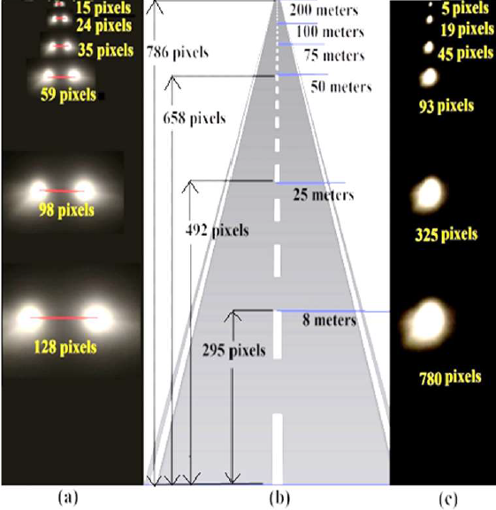
Fig. 5 Three defined rules for vehicle distance estimation in a frame with 1280×786 resolution; (a) Horizontal distance (centroid's Euclidean distance) between the two headlights; (b) Heights of two headlights in a frame and their equivalent distance from the baseline of the road; (c) Area of a headlight (i.e.-number of high-intensity pixels available)
4.4 Distance and Speed Estimation of Vehicles
After calculating the above three important features, the distance of an oncoming vehicle can be estimated. The following three different ways are defined to estimate the distance Viz:
i) d1 = estimated distance from way1 (i.e., from horizontal distance between the two headlights),
ii) d2 = estimated distance from way2 (i.e., from heights of two headlights from baseline),
iii) d3 = estimated distance from way3 (i.e., from the area of the headlight).
The estimated distance may not be the same in all the procedures. Therefore, normalization is done from the three estimations as follows.
where age_pair = average of the closest pair from (d1 ,d2 and d3), and single = the distance which is not in closest pair.
The speed of the vehicles is then estimated. To compute the relative speed of two vehicles, vehicle-to-vehicle distance is estimated at last ten frames with an interval of ten frames. The difference between two distance obtained in nth frame (current frame) and (n+10)th frame is estimated as follows:
Relative speed
where D(n0)difference indicates a change of distance in every 10th frame. The relative speed is calculated considering 30fps video and its unit is km/hr. The actual speed of ongoing and oncoming vehicles are calculated as follows:
where β and αT indicates the relative speed and actual speed of test vehicle respectively.
Let us consider the complex traffic situation of three vehicles at night. Vehicle "A" and "B" is in the same direction and "C" is oncoming vehicle in the adjacent lane as projected in figure 4. So, the actual speed of 'B' and 'C' is calculated as follows:
Similarly, the actual speed of 'C':
4.5 Features Formulation
After calculating all the distance and speed, the mathematical formulation of the decision of overtaking is constructed as follows.
Let us consider the adverse situation of three vehicles (one vehicle is in the front in the same direction and another vehicle is coming in the adjacent lane from the opposite direction of the test vehicle) at night as represented in figure 6.
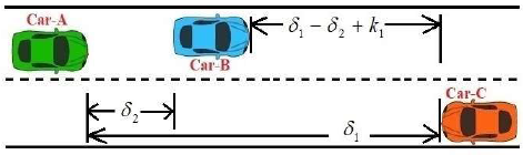
Fig. 6 Overtaking in an adverse situation where one vehicle is in the front of another vehicle and another one vehicle is coming in the adjacent lane from the opposite direction
Let, the speed of any vehicle is represented by α and the relative speed of two vehicles is represented by β. Let the relative speed of vehicle A and C = x km/hr. So:
and relative speed of A and B is y km/hr, i.e.,
so:
or:
or:
or:
This is the relative speed of B and C, i.e.- the sum of the speed of B and speed of C.
Let, distances from A to C dist(A,C) and A to B dist(A,B) are δ1 meter and δ2 meter respectively. So:
where k1 is a constant for safety purposes. Here, k1 = 10 meter is used for safety.
Accordingly, the time needed for B and C to cross (δ1 - δ2 + k1) meter distance with a speed of 5*(x-y)/18 meter/second is calculated from (9, 10) as follows:
Therefore, vehicle A has to overtake vehicle B within T1 second of time. The relative distance that needs to be covered is as follows:
where k2 is a constant for the extra safety purpose (as the vehicle need to cover the extra length of two vehicles and few more angular distance for changing the lane and for returning to the previous lane). Here, the value of k2 = 8 meters is used for safe overtaking. Therefore, the minimum relative speed of vehicle A over vehicle B is estimated as follows:
Required relative speed of A and B
So, vehicle A has to run
However, the relative speed of A and B is y km/hr. So, A has only y km/hr more speed than B. So, an increment of speed required for vehicle A is calculated as follows:
So, if
where x is the displacement, a is the acceleration, 't' is time between initial and final position, and u is the initial speed of vehicle A. Here, the preliminary speed of vehicle A is known as it is our overtaking vehicle. As the system is installed in the vehicle (A), so speed can be retrieved easily. From (11, 12, 16) we got:
4.6 Road Condition Detection
For the perfect overtaking decision, detection of road condition is also essential. Here, the road condition level is estimated by considering vertical displacement of light. Maximum displacement of 200 pixels is considered if the road condition is extremely bad and have many speed breaker and potholes in the road. The output value of the road condition level is finalized within 0 to 10 by dividing the average displacement of light centroid by 200. Where 0 indicates a smooth road with no potholes and 10 indicates an extreme bad road with many potholes. The estimation has been completed as pseudo code 1.

4.7 Overtaking Decision Based on Fuzzy Logic
The decision-making system is designed based on fuzzy logic using the Mamdani method [40]. Input membership functions in the proposed system are the condition of the road and the required acceleration.
The Value of the required acceleration is divided, where greater than 4 indicates a high value of acceleration that may be risky in the sense of driving. Figure 7(a) and figure 7(b) represents the membership functions of the required acceleration and condition of the road.
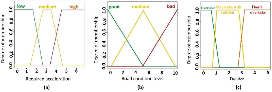
Fig. 7 (a) Membership functions of required acceleration, (b) Membership functions of road condition level, (c) Membership functions of output
Finally, three types of final decision are generated, viz: - a) overtake with confidence, b) overtake with caution and c) don't overtake. Figure 7(c) represents the output membership function.
The rules used in decision-making system is exposed in Table 1. The 3D visualization of the relationship between input and output result of the decision-making system is represented in figure 8.
Table 1 Fuzzy rules for fuzzy decision
| Required Acceleration | ||||
|---|---|---|---|---|
| Below 2.0 (low) | 2.0 to 4.0 (medium) | Above 4.0 (high) | ||
|
Road Condition Level |
Below 2.5 (good) | Overtake | Overtake with Caution |
Don’t Overtake |
| 2.5 to 7 (medium) | Overtake with Caution |
Don’t Overtake | Don’t Overtake | |
| Above 7 (bad) | Overtake with Caution |
Don’t Overtake | Don’t Overtake | |

5 Real-Time Performance Evaluation
The proposed approach is tested in real-time during the night on two-lane single-carriageway roads. Two lanes have no separation and vehicles run in both directions. Empirical tests are conducted in complex traffic situations where cars are running in both directions on the two lane single carriageway. The accuracy in terms of errors of speed and distance estimation is shown in Table 2.
Table 2 Accuracy of Distance and Speed Estimation
| Vehicles | Estimates value |
Ground truth Value obtained from GPS |
Error | Mean error | |
|---|---|---|---|---|---|
| Distance | 1 | 32 m | 32 m | 0 m | 1.1 m |
| 2 | 95 m | 94 m | - 1 m | ||
| 13 | 126 m | 128.5 m | + 2.5 m | ||
| 4 | 51 m | 50 m | - 1 m | ||
| 5 | 76 m | 77 m | + 1 m | ||
| Speed | 1 | 30 km/hr | 31 km/hr | + 1 km/hr. | .4 km/hr |
| 2 | 42 km/hr. | 41 km/hr. | - 1 km/hr. | ||
| 3 | 50 km/hr. | 52 km/hr. | + 2 km/hr. | ||
| 4 | 61 km/hr. | 59 km/hr. | - 2 km/hr. | ||
| 5 | 54 km/hr. | 53 km/hr. | - 1 km/hr. |
There are no existing methods available, which can estimate the real-time distance and speed of any vehicle accurately at night. However, a compression among the proposed method and state-of-the-art techniques for distance and speed estimation (in terms of average error from 25 frames in percentage) of vehicles in real-time is revealed in Table 3.
Table 3 Compression of the Proposed Method with State-of-The -Art Techniques for the Distance and Speed Estimation
| Error (average of 25 frames in %) of various distance estimation methods | |||||
| Javadi et al. [9] | Kim et al. [11] | Liu et al. [15] | Vakili et al. [16] | Ali et al. [17] | Zaarane et al. [18] |
| 3.455 | 3.426 | 2.713 | 2.713 | 2.374 | 1.84 |
| Error (average of 25 frames in %) of various speed estimation methods | |||||
| Great et al. [3] | Hua et al. [5] | Giannakeris et al. [6] | Koyuncu et al. [7] | Javadi et al. [9] | Moazzam et al. [12] |
| 4.872 | 3.032 | 4.945 | 3.715 | 2.707 | 2.425 |
A sample frame during a real-time experiment in a complex traffic scenario where the distances and speeds of both ongoing and oncoming vehicles are estimated is revealed in figure 9 with two different modes of view.
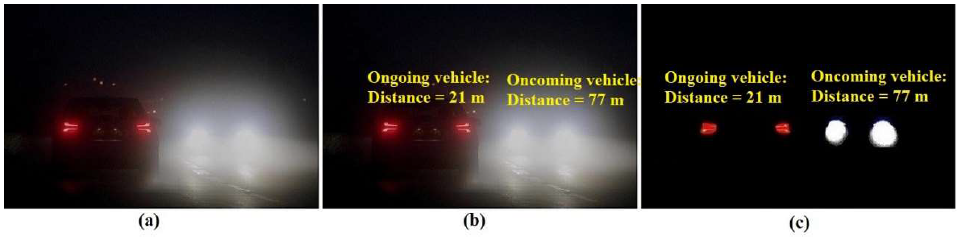
Fig. 9 a) A real-time input frame b) Distance and speed estimation c) Special mode with processed frame
The proposed system has been tested during night time dark conditions in the two-lane single-carriageway road where no separation is present between two lanes and vehicles run bidirectionally. In this test, a particular situation is considered where car A and B are running in a similar direction and car C is driving in the opposite direction in the right lane. It is expected that the situation will allow car A to overtake car B while considering car C.
The accuracy obtained in real-time observation is shown in Table 4. After several real-time experiments, a total of 46 realistic decisions has been observed, out of them, few are shown in Table 5.
Table 4 Real-time observation of overtaking accuracy
| Threshold value used |
Total of overtaking situations observed |
Number of fuzzy decisions of overtaking (Overtake + Overtake with caution) |
Number of realistic safe overtaking scenario observed |
Number of failure estimation |
Accuracy in % |
|---|---|---|---|---|---|
| Set 1 | 46 | 34 | 32 | 2 | 94.12% |
| Set 2 | 46 | 34 | 34 | 0 | 100% |
Table 5 Real-time observation of overtaking decision
| Number of overtaking situations observed |
Required acceleration (m/s2) |
Road Condition level |
Threshold value Used: SET 1 | Threshold value Used: SET 2 | ||||
|---|---|---|---|---|---|---|---|---|
| Fuzzy decision |
Realistic scenario observed |
Estimation: success/ failure |
Fuzzy decision |
Realistic scenario observed |
Estimation: success/ failure |
|||
| 1st | 5.65 | 6 | Don’t overtake |
Safe, as no overtake |
success | Don’t overtake |
Safe, as no overtake |
success |
| 2nd | 2.67 | 2 | Overtake with Caution |
Safe, as overtaken carefully |
success | Overtake with Caution |
Safe, as overtaken carefully |
success |
| 3rd | 1.02 | 1 | Overtake | Safe overtake |
success | Overtake | Safe overtake |
success |
| 4th | 2.85 | 6 | Don’t overtake |
Safe, as no overtake |
success | Overtake with Caution |
Safe, as overtaken carefully |
success |
| 5th | 3.95 | 2.4 | Overtake with Caution |
Risky condition during overtaking |
failure | Don’t overtake |
Safe, as no overtake |
success |
| 6th | 4.50 | 7 | Don’t overtake |
Safe, as no overtake |
success | Don’t overtake |
Safe, as no overtake |
success |
Two sets of threshold value used in real-time experiments are:
Set 1. Required acceleration: less than 2.0 (low), 2.0 to 4.0 (medium) and above 4.0 (high),
Road Condition Level: less than 2.5 (good), 2.5 to 7.0 (medium) and above 7.0 (bad).
Set 2. Required acceleration: less than 2.0 (low), 2.0 to 3.0 (medium) and above 3.0 (high),
Road Condition Level: less than 2.5 (good), 2.5 to 6.0 (medium) and above 6.0 (bad).
4.8 5.1 Analysis of Computation Time
The computation time is the most decisive factor in the case of driving. Numerous real-time experiments reveal that the computation time is amazingly less so that the drivers can see the distance and the speed of other vehicles in real time without any time delay. The processing time is exposed in figure 10.

6 Conclusion and Future Work
The real-time dark road at night is really dangerous for driving because the driver cannot see another vehicle properly. Making a perfect decision of overtaking is complicated for humans and obviously for any machine by observing headlights and taillights of other vehicles. Till now, no such decision-making algorithm exists which can make a perfect overtaking decision at night time and adverse situation.
The proposed system is presented as a novel vision-based overtaking decision-making technique during night time adverse situations. Different situations are considered with three vehicles viz: a slower front vehicle, opposite oncoming vehicle and test vehicle. The proposed system can estimate vehicle-to-vehicle distance, speed of vehicles, road condition level, the required gap and acceleration for safe overtaking in real-time.
The system can take a real-time fast and accurate decision of overtaking. The decision is estimated depending on the distance and speed of other vehicles and the required gap in the presence of an oncoming vehicle at night. The proposed system will be very helpful for safe overtaking in two-lane bidirectional road for night time driving. It will add an evolutionary benefit to autonomous vehicles as well as manual driving.
As future work, more complex evaluation scenarios can be considered, such as additional traffic travelling on multiple lanes in different directions, or having different traffic participants in addition to vehicles (e.g., bikes). Moreover, the vehicle-tracking algorithm at night would need to be extended to address the dark vehicle (vehicle at parking mode) without any headlight.

