


 nueva página del texto (beta)
 Inglés (pdf)
 Artículo en XML
 Referencias del artículo
 Enviar artículo por email
 Citado por SciELO
  Similares en
SciELO
Similares en
SciELO 
 Permalink
1. Introduction
Friction surfacing (FS) is a solid-state coating technology derived from the basic principles of friction welding. The process involves rotating a solid consumable rod of the coating material and pressing it axially against the surface to be coated (the substrate). Frictional heat is generated between the two surfaces producing a viscoplastic boundary layer at the rod’ tip. Traversal movement of the rotating consumable rod, relative to the substrate, deposits the plasticized material and allows producing a fine-grained coating on the substrate. The bonding strength between the two surfaces depends on the types of materials and the process parameters. The FS process allows the joining of dissimilar materials metallurgically incompatible or difficult to join by fusion-based techniques. The process has been used for different purposes such as reclamation of worn or damaged components, localized enhancement of surface properties of tools, and many other applications. As a solid-state process, FS is more energy efficient, cleaner, and more environment friendly when compared with other alternatives (de Macedoa et al., 2010). Although patented about 80 years ago, FS became well-established only in the past three decades. A good review of the literature on FS up to the year 2014 was provided in (Gandra et al., 2014). The authors also gave a detailed description of the thermomechanical and microstructural transformations under different FS conditions and discussed various modeling approaches and relevant technology developments. The FS process has been tested on a wide range of metal combinations. This includes alloy and stainless steels, aluminum, magnesium, and titanium alloys, and many other materials. Aluminum alloys, especially fusion-unweldable ones, are of high interest to the industry as candidates for FS applications. As pointed out in (Kumar, 2020), deposition of aluminum over mild steel by fusion welding is not feasible because their chemical reaction forms iron aluminide while elements Fe and Al are immiscible. Solid-state FS therefore presents a valuable solution.
The mainstream topic of the published research on FS has been the optimization of the process parameters for various quality features of the deposition. Focus is often made on three of the process parameters including rotational and travel speeds of the consumable rod and the axial pressing force. In (Sahoo et al., 2020), the effect of FS parameters when depositing AA6063 alloy over IS2062 mild steel substrate were investigated. The authors obtained a high-quality bond and finer grains by using a relatively low rotational speed with higher travel speed and axial pressing force. FS of AA6351-T6 alloy on 5052-H32 at different levels of travel speed and rod feed rate were studied in (Galvis et al., 2017). The authors tested the produced layers for bending strength, microhardness, and microstructural transformations. The highest deposition quality and bending strength were achieved at 4 mm/s travel speed and 5.5 mm/s rod feed speed. Other researchers examined FS deposits of AA6063 alloy over stainless steel AISI316. Among the tested process parameter levels, a rotational speed of 2400 rpm combined with 150 mm/s travel speed and 5-kN axial force was shown to ensure the highest deposition efficiency (da Silva et al., 2018). The feasibility of FS AA5083-H112 alloy over AA2024-T3 substrates were assessed in (Silvério et al., 2018) and showed that the deposition increased the tensile strength of the substrate. In a recent study, the process parameter effects on microstructure and properties of solid-solutionized AA2024 coating over AA1050 were tested. It was found that increasing the rotational speed, traverse speed, and axial feeding rate reduces the bonded zone. Also, the solutionized rod led to a thinner coating in all FS parameters compared to coatings made by a rod with T3 heat treatment. The maximum coating hardness and shear strength were obtained by rotational speed, traverse speed, and axial feeding rate of 1000 rpm, 100 mm/min, and 75 mm/min, respectively (Rahmati, 2021).
In some applications, FS is performed using a consumable rod and substrate of the same material. Koushik et al. (2014) used FS to modify the surface properties of wrought aluminum alloy AA2014. As this alloy is known to have poor wear and corrosion resistance, the authors used FS with a rod of the same alloy to improve these properties. The surface improvements were attributed to plastic deformation and mixing during friction surfacing that led to break-up of coarse copper rich eutectic particles, dendrite structure, and more uniform distribution of fine copper particulates. One of the developments made to FS technology is the underwater process. An early investigation of underwater FS was conducted by Li and Shinoda, (2000) who used a quench hardenable martensite steel as the coating material on a low carbon steel substrate. It was shown that underwater deposition of the coating was more efficient than in air. Quench cracks were not observed. Relying on the findings in (Li & Shinoda, 2000), Krohn et al. (2015) used water-cooled FS to deposit AA6082 T6 over AA2024 T53. The purpose was to investigate the advantages of underwater FS for aluminum alloys and as well, to study the effect of the cooling system configuration on the process. A distilled water spray cooling system was used with spray directed either on the deposited layer, flash, or both. The authors reported a substantial increase in the deposition efficiency from 19% to 31%, without affecting the properties of the deposited material. Another development in FS technology was tested in (Bararpour et al., 2019) where the authors utilized FS for mechanical alloying purposes producing metal matrix composites. Zinc powder was packed inside 2.5-mm diameter holes drilled longitudinally in an AA5083 consumable rod. The rod was deposited on an AA5052 sheet. Subsequent X-ray diffraction tests confirmed Zn dissolution and formation of a solid solution due to friction surfacing. In a quite recent study, FS of AA6061 over Q235 plain carbon structural steel were studied and showed that the microstructure of the coating was highly refined by FS. The dimensions of the coating were found to be highly affected by the rod rotational speed. The ultimate width and thickness of the coating were reached at 1600 rpm (Yu et al., 2021).
To conclude, the FS process has been established as a green and efficient surface engineering technology. Like other manufacturing processes, success of a FS operation is highly dependent on the process parameter settings. As the literature shows, optimum FS process settings are seen to vary widely, depending not only on material types, but also on which surface or mechanical properties are being targeted in the application. This has made it necessary to conduct separate testing and research virtually for each material combination.
This work investigates the effects of process parameter settings for depositing aluminum alloy AA6061 over mild steel AISI1017. In spite of the widespread use of this aluminum alloy in different applications, detailed results for its deposition over steel have not been well-documented. It is worth mentioning here that experiments were conducted in the past by Batchelor et al. (1996) where this alloy failed to deposit over steel under the attempted process settings. The unsuccessful deposition was attributed to the high thermal conductivity of the AA6061 consumable preventing the viscoplastic deformation of the rod tip. This paper demonstrates that successful deposition of this alloy over steel is possible under certain combinations of the process parameters.
2. Materials and methods
The experiments were carried out on a 3-axis vertical milling machine which was adapted to the purpose of friction surfacing. The consumables were 20-mm diameter AA6061 solid rods deposited on a 10-mm thick AISI1017 steel plate. To perform a FS procedure, the consumable rod is given a certain rotational speed and pressed down hard against the substrate. After pre-friction for few seconds, the rod is moved relative to the substrate at a specified travel speed. At the end of the deposition stroke, the rod is lifted, and the deposited layer is allowed to cool down to room temperature before it is unclamped. This procedure was repeated at different rotational and travel speeds combinations of the consumable rod. It is worth mentioning here that the substrate plates were roughened before the deposition process. Surface roughening was decided after several failed attempts to perform the process on a smooth substrate.
The experiment was designed with four levels of the rotational speed and three levels of the travel speed (see Table 1). These levels were chosen considering the capabilities of the used milling machine. Three replicates were planned from each speed combination resulting in a total of thirty-six sample for testing. However, the replicates produced using the lowest attempted rotational speed (800 rpm) were excluded from further analysis as the depositions at this speed were unsuccessful regardless of travel speed. Table 2 shows photos of unsuccessful depositions obtained at this speed, among other depositions.
Table 2 Flash shapes and resultant depositions
| 800 rpm | 1000 rpm | 1250 rpm | 1600 rpm | ||
|---|---|---|---|---|---|
| 35 mm/min | Flash Shape |

|

|

|

|
| Deposited Layer |

|

|

|

|
|
| 45 mm/min | Flash Shape |

|

|

|

|
| Deposited Layer |

|

|

|

|
|
| 55 mm/min | Flash Shape |

|

|

|

|
| Deposited Layer |

|

|

|

|
The test coupons were assessed using quantitative and qualitative methods. Quantitative assessment included measuring the deposition efficiency (ηp), surface roughness (Ra), layer volume (V), and material hardness. Analysis of variance (ANOVA) with a 0.05 significance level was used to study the effects on these variables. Qualitative evaluation, on the other hand, was done by inspecting the stability and uniformity of the deposition process, as well as microstructure testing. Samples for metallographic examination were polished using 1-μm diamond particles, etched in Keller’s reagent for 5 to 7 seconds, and washed with alcohol.
3. Results and discussion
3.1. Surface roughness
The surface roughness (Ra) of the deposited layers was measured using an optical 3D profilometer. ANOVA revealed that lower roughness values corresponded with higher rotational speeds, with F = 7.16 and p = 0.021. The travel speed had no significant effect on surface roughness. Figure 1 summarizes the performed measurements. The roughness had average values of 0.861, 0.470, and 0.312 μm for rotational speeds of 1000, 1250, and 1600 rpm, respectively. The observed roughness improvements can be explained by the fact that for any given press force and travel speed, a higher rotational speed leads to higher heat input rate, which in turn leads to more softening and plasticizing of the deposited material. Thus, better material transfer and deposition and smoother layers were obtained compared to those at lower rotational speeds, as illustrated in Table 2.

3.2. Layer volume
The volume of a deposited layer was estimated by measuring the layer cross-sectional dimensions. Each coupon was sectioned using a band saw and polished. An optical profilometer was used to capture cross-section macrographs from which the cross-section dimensions were extracted by imageJ software. ANOVA revealed that layer volume is significantly affected by the rotational speed (with F = 190.9 and p = 0.000), while the travel speed had no significant effect on it. As Figure 2 shows, deposition replicates produced at 1600-rpm rotational speed combined with 35-mm/min travel speed had the largest volumes. This can be justified by the fact that at such speeds, heat generation rate is high while dissipation rate is low. In this case, one should expect a higher transfer rate of material to the substrate and hence bigger layer volume.

3.3. Deposition efficiency
The efficiency of the deposition was calculated as the ratio of the deposited material mass to the rod’s original mass. The deposited mass was measured indirectly by weighing the rod before and after deposition. So, the deposition efficiency (ηp) was calculated using Eq. (1).
As per the ANOVA results, the deposition efficiency is significantly affected by both the rotational and travel speeds, with (F = 28.00, p = 0.001) and (F = 7.14, p = 0.026), respectively. As Figure 3 shows, the highest efficiency of 53.6% was achieved at the highest tested rotational speed (1600 rpm) combined with the highest tested travel speed (55 mm/min). An explanation to this occurrence can be that at these relatively high speeds, the rate of heat generation is high enough to rapidly soften the material at the rod’s tip, but the high travel speed prevents this softening from propagating up the rod. In contrast, depositing at a lower travel speed of 35 mm/min with high rotational speeds led to excessive softening, which in turn caused the rod to lose its stiffness and start to buckle and bend under load. On the other hand, depositions at the low-level rotational and travel speeds were all unsuccessful. Table 2 shows images of deposited layers obtained at different speed combinations.

3.4. Deposition stability
Deposition is said to be stable if the material transfer rate to substrate is uniform. Ideally, the deposited layer should have straight, parallel sides and a relatively uniform thickness. Flash formation on the other hand, should be of circular shape.
Therefore, the process stability in our experiments was judged based on the obtained layer and flash shapes, by comparing them with the ideal patterns.
As Table 2 shows, the highest deposition stability was achieved at 1600-rpm combined with 55 mm/min speed. However, as ANOVA showed, the rotational speed has a stronger effect on stability since layer uniformity is improved as the rotational speed is increased, regardless of the travel speed. Basically, the shape of mushroom flash can be explained by fact that as rotational and travel speed increases, appropriate heat input is expected, hence appropriate material plasticizing, softening, particularly at center area, and hence more symmetrical and circular shape of flash as well as more uniform, straight, parallel sides and relatively uniform thickness of deposited layer.
3.5. Hardness
Using Vickers test, the hardness of each deposition was measured at two locations, namely, at deposited layer surface and at layer interface with the substrate materials. Test specimens were prepared following the accepted procedure including cutting, mounting, grinding, and polishing. Hardness measurement results at the two locations are provided in Fig. 4a and b. Overall, the interface hardness was higher than that of the layer surface. ANOVA shows that the interface hardness affected negatively by the rotational speed (with F = 19.00 and p = 0.011).


The higher interface hardness can be due to the partial mixing of the substrate material with that of the softer deposit, especially that the substrate surface was roughened prior to deposition. As for the layer surface hardness, it is significantly affected by both rotational and travel speeds, with (F = 25.00, p = 0.001) and (F = 8.14, p = 0.021), respectively. The highest hardness was achieved at 1600-rpm in combination with 55-mm/min speed. More insight into the obtained hardness effect can be gained by examining the material microstructure under different speed settings. Figure 5 shows the microstructure of the raw AA6061 material, while Figures 6, and 7 are samples from the deposited material and the EDX analysis indicating the composition of a selected area from the deposited layers.


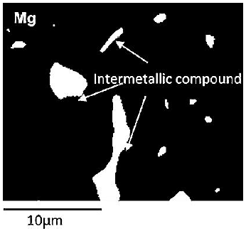
Figure 7a Backscattered SEM image showing a selected area from the deposited layers within sample shown in Figure 6c for EDX.

The spectra in Figure 7b showed that all element within the deposited layer is similar to that of AA6061 rod. Moreover, the backscattered image (Figure7a) for a selected area within the deposited layer revealed that the intermetallic compounds (dark areas) were Mg- rich, usually known to be Mg2Si. In AA6061, Mg2Si considered as a main contributor for the hardening and strengthening (Zeid, 2019).
As pointed out in (Ogunsemi et al., 2021; Polat et al., 2015), a higher rotational speed corresponds with a greater thermomechanical power, which causes more extensive grain and intermetallic compounds fragmentation and continuous dynamic recrystallization. This in turn yields finer grains and leads to more precipitate and intermetallic compound dissolving. On the other hand, the higher the travel speed, the faster is the heat dissipation and so the less is the chance for the grains and precipitates to grow in size. We therefore can observe fewer dark areas in the microstructure in Figure 6c compared to Figure 6a. This also justifies the smaller percentage of magnesium silicide (Mg2Si) in the samples deposited at high rotational and travel speeds. This result is consistent with the conclusions made in (Abd El-Azim et al., 2016; Mortazavian & Fatemi, 2015) for AA6061, where the finer the grains and precipitates, the higher is the hardness.
ANOVA results for all response variables for rotational and travel speeds are summarized in Table 3, with F-value and p-value for each response variable. In addition, Table 3 shows the coefficient of correlation (R-seq) for each response variable to explain the strength of relationship between independent variables (factors) and dependent variables (responses).
Table 3 Summary of ANOVA for all the all response variables for both factors.
| Response variables | Factors | Coefficient of correlation | |
|---|---|---|---|
| Rotational speed | Travel speed | ||
| Deposited volume (V) | F=174.9, p=0.000* | F=1.06, p=0.404 | 98.87% |
| Layer roughness (Ra) | F=7.16, p= 0.021* | F=1.31, p=0.337 | 80.07% |
| Deposition efficiency (ηp) | F=28.00, p=0.001* | F=7.14, p=0.026* | 94.25% |
| Deposit hardness (HV) | F=25.00, p=0.001* | F=8.14, p=0.021* | 96.25% |
| Interface hardness (HV) | F=19.00, p=0.011* | F=1.65, p=0.317 | 95.47% |
| *Significant at 5% | |||
4. Conclusion
Friction surfacing of AA6061 alloy on mild steel can be successful provided the process is performed at high rotational and travel speeds as proved in this work. Also, good deposition is only possible if the substrate surface is roughened prior to deposition. The travel speed is less significant to the process than the rotational speed except for the deposit hardness, where higher travel speeds result in higher hardness. Among the attempted speed settings, the best deposition results were obtained at 1600 rpm rotational speed with 55 mm/min travel speed. These settings produced the most uniform, flat, and thick layers, with higher hardness and process efficiency.
Conflict of interest
The author(s) does/do not have any type of conflict of interest to declare.
Financing
This research was supported by the Deanship of Research at Jordan University of Science and Technology, Grant No. 20190511.

