


 nueva página del texto (beta)
 Artículo en XML
 Referencias del artículo
 Enviar artículo por email
 Citado por SciELO
  Similares en
SciELO
Similares en
SciELO 
 Permalink
1. Introduction
Demand for energy sources is increasing in a fast pace. At the same time need for ecofriendly sources for much sustainable world is highly required. In this context wind energy plays an important role in energy industries as it is a clean renewable source of energy discussed by Polinder et al. (2013).
Proper selection of wind generator plays an important role in wind energy conversion system (WECS). Generator topology is selected after considering its overall cost, control potential, protection, integration cost, among others. Squirrel cage induction generator (SCIG), doubly fed induction generator (DFIG) and permanent magnet synchronous generator (PMSG) are commonly used WECS generators. At the early stages squirrel cage induction generator connected through shaft and gear box was used. Since wind is highly varying in nature and SCIG is a constant speed generator wind industry cannot depend on SCIG for increasing power demand due to its less power output and higher mechanical stress. Also shaft and gear box of SCIG makes system complex and costly. Research started on variable speed generators which is capable of high energy capture and lower mechanical stresses by Moness and Moustafa (2016), Polinder et al. (2006). After 1990s wind industry start utilizing doubly fed induction generator which is variable in nature and able to capture power at different wind speeds by using power electronics converter topologies. Both stator and rotor has to feed from AC supply. Being a high-speed generator, DFIG requires gearbox mechanism and auxiliary equipment for producing reactive volt amperes. Now a days wind industry starts depending on PMSG, which is a low-speed generator. Since it is a low speed generator it does not requires a gear box and easy to control using variable speed converters by Navarrete et al. (2019).
Power converters play the role of power conditioning in WECS by adjusting generator frequency and grid voltage. For fixed speed generators, thyristor acted as soft starters. Shifting of WECS to variable speed generators require more power conditioning requirements like adjusting of generator voltage with variation in wind speed, matching of frequency with grid frequency, control of active and reactive power, harmonics etc. Power electronics technology had undergone progression by decreasing number of components in order to improve reliability and reduce cost. WECS make use of frequency converter type AC-AC converters as it controls both voltage magnitude and frequency. These converters are of direct and indirect types. In Indirect type generated AC is converted to DC then passes through rectifier stage, DC link capacitor and then inverter stage. Cyclo-converters and Matrix converters can be used as direct converters.
Converter system can also be classified as grid commutated and self-commutated commutator systems. Grid commutated are high power thyristor commutators with six, twelve or more pulses. Mostly used converter systems are self-commutated equipped with PWM control. This converter system can transfer active and reactive power in both directions investigated by Polinder (2011), Carroll et al. (2015).
Converter has to satisfy both generator side and grid side requirements. At generator side converter has to control stator current which is required for controlling rotating speed. This helps in extracting maximum active power from wind by controlling wind torque. At grid side converter has to maintain frequency and amplitude of voltage as constant according to the active and reactive power requirement of the grid. Also, total harmonic distortion (THD) should be maintained as low as possible explained by Yaramasu et al. (2015), Chatterjee and Chatterjee (2018), and Blaabjerg et al. (2006). In order satisfy all these requirements, in this paper IGBT-based two level back-to-back converter is used. High voltage capability, ease of drive, low ON resistance relatively fast switching speed of IGBT provides better self-commutation.
Research is being done for better extraction of energy from wind by adopting better control algorithms, better converter topologies and various techniques. Recent works of the literature propose maximum power tracking without wind speed sensors. In Deng et al. (2020) the authors estimated the wind speed from the available data like pitch angle, torque, and generator speed. The wind speed estimation is mainly done by soft computing techniques. A support vector machine algorithm is used for wind speed estimation in Abo-Khalil and Lee (2008). The estimated and measured wind speeds matches with each other but there is a delay occurs in the system. It affects the dynamic performance of the system.
Efficiency of WECS can also be improved by improving power quality of the system. Power quality is improved with a self-excited induction generator (SEIG) in Amin and Mohammed (2011). Active and reactive power injected into the grid is fully controlled using a voltage source inverter (VSI) as a dynamic volt ampere reactive (VAR) compensator.
Research is being conducted for the development of better MPPT algorithms which can contribute more to the better system performance. An intelligent maximum power point tracking (IMPPT) considering short-term wind speed prediction, wind turbine dynamics, and MPPT is used for maximum output and cost minimization in large scale WECS in Huang et al. (2015), Konstantopoulos and Alexandridis, (2014).
From Raza et al. (2011), it is clear that among the various MPPT methods, the application of hill climbing method does not require any previous knowledge and algorithm does not consider turbine, generator and wind qualities. Perturb and observe algorithm is used on both generator side and grid side converters for better extraction of power in Pindoriya et al. (2017). Wind energy conversion system with high efficiency with less power loss is obtained in megawatt by the use of low voltage current source converter based on PWM technique in Jianwen et al. (2016). Unattainable levels of efficiency are made possible by the use of sliding mode control in PMSG. This method make use of d axis and q axis current and high-speed shaft rotational speed to obtain high efficiency in Errami et al. (2015).
A neural network-based control is proposed in which avoids the used of wind speed sensor.
The look-up table-based technique uses the characteristics of output power and shaft speed of the wind turbine generators. These schemes depend on the characteristics of wind turbines, which tend to change over time in Li et al. (2019).
Fuzzy logic controllers (FLCs) incorporate an alternative trend rather than the proportional integral control (PI) control strategies to handle the characteristics of non-linear dynamic systems. The FLC employs fuzzy logic as a design methodology, which can be utilized in promoting the systems non-linearity for embedded control strategy. The FLCs have some salient features, such as efficient to handle the characteristics of non-linear system dynamics, model-free approach, and simple design requirements in Muyeen and Al-Durra (2013). The most of the classical FLCs reported in the literatures are based on a fixed membership functions and a static rule base. Sometimes the classical FLC is not sufficient to cope up with the non-linear systems that exhibit a high degree of uncertainty by Yin et al. (2015). In Do (2017) Fuzzy control is incorporated with sliding mode control but sliding mode control depends on the system model. Despite the robustness of FLCs, sometimes the classical FLC is not sufficient to cope up with the nonlinear systems that exhibit a high degree of uncertainty. Hence adaptive filtering technique is used for on-line update of the scaling factors of the fuzzy logic controllers by Soliman et al. (2019), Zhao et al. (2014). This work focus on the study of the heuristic control algorithm with fuzzy logic-based control for extraction of maximum power from wind energy conversion systems. The control do not require the exact model of the system and the measurement of wind speed. VSC-based multilevel HVDC helps to maintain DC voltage and the power loading rate of each converter within their limits during large disturbances by adopting droop control scheme which considers both deviation and power sharing factor in Chen et al. (2017).
This paper proposes a continuous mixed p-norm CMPN algorithm for FLCs to enhance the performance of the grid-tied PMSG WECS. Section 2 shows the system and modelling of the WECS. The proposed control strategy of machine side converter is discussed in Section 3 and grid side converter in Section 4. A detailed simulation results and analysis are given in Section 4. The results are validated with the help of a laboratory prototype and are discussed in Section 5 and Section 6, and conclusions in Section 7.
2. System description and modeling
Proposed system consists of a permanent magnet synchronous generator which is connected to wind turbine blades. A two-stage converter called back-to-back converter with insulated gate bipolar transistor (IGBT) switches is used in this system as in Figure 1. Output of PMSG is fed into a full wave rectifier with IGBT switches. IGBT switches helps in low harmonic generation, large variation in voltage and frequency at input AC side. Rectified Dc is fed into DC link capacitors which smooth the wave and make inverter output more stable by proper filtering. Dc link capacitor forms the input sides of IGBT switch-based voltage source inverter (VSC). Proper switching of inverter by providing gating pulse at right instants produces AC output which can be connected to grid. Inverter and converter switching is controlled by using adaptive fuzzy logic controller with Continuous mixed P-Norm algorithm (CMPN) and Mamdani’s max-min technique of defuzzification. The system analysis is done with the proposed system by connecting both linear and nonlinear loads connected to the grid.

2.1. Modeling of Wind turbine and PMSG
Modelling of wind turbine is done according to the output power required. Captured mechanical power of wind turbine is
Where,
A is area swept by rotor blades A=
Tip speed ratio,
ω m - speed of wind turbine, R -Radius of turbine blades
Maximum power coefficient
Where C1 to C5 indicates coefficient of wind turbine characteristics.
C1 = 0.5, C2 =98,C3 =0.4,C4 =5,C5= 16.5.
Power output is proportional to cube of wind velocity. Cut in speed is the speed range at which maximum possible output is obtained in a wind turbine. Before cut in speed power output will be zero. In order obtain stability in system above the cut in speed power output should be controlled to a constant value by controlling the pitch angle in such a way to obtain zero power output.
Variation of power coefficient with respect to change in tip speed ratio and blade pitch angle is indicated in Figure 2. Variation of power coefficient at different speeds is shown in Figure 3.


From the power curve it is clear that maximum power is extracted when the turbine is operated at optimum value tip speed ratio λopt and at a pitch angle of zero degree. There will be an optimal generated speed for each value of wind speed, which is given as:
The maximum value of wind turbine power
The optimum torque is given by,
Here speed of the generator is controlled to get the optimum speed with optimum value of λ. Synchronous rotating frame is used for modelling permanent magnet synchronous generator. Equations are framed by considering two-component axis component in alignment with rotor flux and q-axis component which is quadrature with d-axis.
Where
Lsq and
Therefore, electromagnetic torque can be controlled by controlling quadrature component of stator current isq.
3. Adaptive fuzzy logic-based control of MSC
In the proposed control, the reference generator speed (

The PMSG voltages (
The active power output is calculated from the transformed voltages and currents using the Equations 12 and 13. A low-pass filter isolates the ripples in the power output.
The reference generator speed is compared with actual generator speed and is given to a proportional-integral (PI) control.
As per the torque equation of PMSG, the quadrature axis (qaxis) component of the
generator current is proportional to the electromagnetic torque. Hence, the output
of the PI control is assumed as the reference q-axis component of PMSG (
The

3.1. Fuzzy logic control
The FLC is used for power conditioning in converters is shown in Figure 6. The error signals and change in
errors are received as input signals of FLC. The error signal of generator speed (

Scaling will help in obtaining better performance under varying conditions. Time
delay for one sampling is taken as

Linguistic variables for fuzzy system is defined as negative big(NB), negative
small (NS), zero, positive big (PB) and positive small (PS).Grade of input and
output membership function
Where,
Table 1 Fuzzy rules for FLC.
| Output | ∆eu(k) | |||||
|---|---|---|---|---|---|---|
| NB | NS | Z | PS | PB | ||
| e(k) | NB | PB | PB | PS | PS | Z |
| NS | PB | PS | PS | Z | NS | |
| Z | PS | PS | Z | NS | NS | |
| PS | PS | Z | NS | NS | NB | |
| PB | Z | NS | NS | NB | NB | |
Mamdani’s max-min technique in Márquez et al. (2007) is utilized for the fuzzy inference mechanism. The basic function of the inference engine is to compute the overall value of the fuzzy output based on the individual contributions of each rule in the rule base. Each individual contribution represents the value of the fuzzy output that is computed by a single rule. The inference method determines directly, the outputs from the knowledge base. Defuzzification is the procedure that produces a real value from the result of the inference that could be used as a fuzzy control input.
The set of modified control output values is converted into a single point wise value. This step produces a quantifiable result in FL. Characteristically, a fuzzy system will have a number of rules that transform a number of variables into a fuzzy result; thus, the result is described in terms of membership in fuzzy sets. For defuzzification, the center-of-area technique is utilized to achieve the output crispy values in Driankov et al. (1993). The coordinate of the centroid corresponds to the defuzzified value (Mn) and is expressed as follows.
Where, N is number of rules,
Initially values of input and output scaling factors of this system is obtained by applying genetic algorithm to get more precise values.so that error signals can be minimised. During the operation CMPN adaptive algorithm is capable of updating scaling factors according to the occurrence of disturbances in the system.
3.2. CMPN adaptive filtering algorithm
Least mean square and least mean fourth were combined in least mean mixed-norm adaptive filter. In Robust mixed norm (RMN) least mean square algorithm is combined with least absolute deviation algorithm. A normalized RMN algorithm was introduced as follows:
Where
Where y(j) indicates output vector of adaptive filter, x(j) - input signal vectors, d(j)-desired signal vectors and w(j) indicates current weight vector of adaptive filter.
Principle of P-norm was used in LMS algorithm by using standard LMS algorithm (p=2). Continuous mixed P-Norm algorithm is used for adaptive filtering since it is a robust mixed norm algorithm. CMPM on-line updates the scaling factors of the fuzzy logic controllers (FLCs) at a high convergence speed.
CMPN algorithm is expressed by the equation as
λj(p) - probability density like weighting function which is bounded by following restriction
Weight vector of CMPN is updated based on Equation (21) and can be indicated as
∇
w(j)
f(j)- instantaneous gradient of
According to single point estimate method expectation
γj is variable step size which depends on e(k). If
In FLC online adaptation of scaling factors is done according to Equation (25). x(j) in Equation (25) indicates actual input signal. This input is updated according to following equations
Comparing Equations (23), (24), (25) change in scaling factors of FLC (
Where
4. Control of grid side converter
The load currents (
The load currents from the abc frame are converted to the dq0 frame as,
resultant d-q currents contain DC component corresponding to the fundamental load
current (
i Lddc is extracted by using a low pass filter (LPF).
The MPPT algorithm produces a reference voltage Vdcref, which is the voltage corresponding to the maximum power point. The sensed DC voltage (Vdc) is compared with the reference (Vdcref) and the error is processed using a PI controller. The output of the PI controller is considered as the active component of current (iwd) drawn from the WECS as,
The reactive component of load is injected by the WECS, making the source current power factor to unity. Hence improves the grid power quality. This is possible by making the reactive component to zero, while generating the reference source current. The reference currents are converted to the abc frame from the dq0 frame considering zero sequence reference source current and quadrature axis current as zero.
The reference current for grid side converter is obtained as,
The input to the controller is the error signal produced by comparing inverter
reference signals and the real-time inverter currents (
5. Results and discussion
5.1. Performance of Fuzzy Logic Maximum Power Tracking Control
The simulation analysis are done using MATLAB/Simulink software. A 25kW wind turbine is modeled and directly coupled to PMSG. As it is coupled without any gear box, the speed of the wind turbine rotor is same as mechanical rotational speed of PMSG. A grid connected system is developed using a back-to-back converter with DC link. To verify the worst condition, a step change in wind speed is assumed. The wind speed is varied as 9m/sec-12m/sec-10m/sec-8m/sec. Figure 8 illustrates the dynamic performance of Type-IV WECS with FLC.
Figure 8 Performance of Type-IV WECS with FLC. Waveforms: wind speed ( v w ), power coefficient (Cp), power output ( Pm ), torque developed (Tm), generator speed ( ω m ).
For wind speed of 8 m/sec and 9 m/sec, the power coefficient reaches to maximum
value but there is a small reduction in the value of power coefficient for wind
speed of 10m/sec and 12 m/sec. It shows that the system works accurately in a
wind speed range of 8m/sec to 9m/sec. The power output (Pm) of wind generator
with step variation in wind speed shows that the power output increases with
increase in wind speed. The variation of torque (
To analyze the performance of FLC control the reference generator speed
corresponding to maximum power point obtained from FLC, and actual generator
speed obtained are compared with optimum speed. The optimum generator speed (
Figure 9 Variation of generator speed with wind speed. Waveforms: wind
speed (
v
w
), optimum generator speed (
Figure 10 illustrates the variation of q-axis component of current. The controller output gives the reference value of q-axis component of generator current. The actual value of q axis component and d-axis component of currents are obtained by measuring the generator three phase currents.
Figure 10 Variation of stator current of PMSG with wind speed Waveforms: quadrature axis current ( i mq ), direct axis current ( i md ).
The three phase currents are converted to d-q reference frame by abc-dq transformation. The reference value of d-axis component is set to zero value to avoid the reactive part of current and making the machine to work at unity power factor. It can be realized that the stator q-axis current increases with increase in wind speed. But there is peak overshoot of current during step changes in wind speed. At time of 6 seconds, the current experiences maximum overshoot at wind speed decreases from 12m/sec to 10 m/sec. The d-axis component is set to zero value as illustrated in Figure 10.
The internal signals of the FLC control, wind speed (
v
w
), estimated optimum speed (
5.2. Performance of Grid Power Quality Control
The grid side converter operates to share the active power from the wind energy
conversion system to the grid. The system is connected to the grid and a local
load. A linear load and a non-linear load are applied to analyze the performance
of the system. The response of the system for a change in load from non-linear
load to linear load is illustrated in Figure
12. It includes grid voltage (
Figure 11 Internal signals of FLC control (a) wind speed of 12 m/sec (b)
wind speed of 8 m/sec. Waveforms: wind speed (
v
w
), reference generator speed(ω*), measured generator speed (
ω
m
), unity sine templates (
ua, ub, uc
),reference q-axis current (
Figure 12 Dynamic performance of GSC with change in load demand. Waveforms:
grid voltage (
Figure 13 Steady state performance of GSC for non-linear load. Waveforms:
grid voltage (
When the load is non-linear, the harmonics present in the load is completely supplied by WECS. Hence the grid current remains sinusoidal. The frequency spectrum of load current and grid currents are shown in Figure 14.

The load current THD is 22.1% but the grid current is maintained at a THD of
1.62%. The variation of the active power of load (
Figure 15 Variation of active and reactive components of power with variation in load demand. Waveforms: active power of the load ( P l ), active power of the source ( P s ), active power supplied by the WECS ( P w ), reactive power requirement of the load ( Q l ), reactive power of the grid ( Q s ), reactive power of the WECS ( Q w ).
Here the wind speed is maintained at a constant value of 9 m/sec. The load demand is varied. From 2 seconds to 2.5 seconds, the active power demand is shared by the grid and the WECS. The reactive power demand of the load is equal to the reactive power supplied by the WECS. The grid reactive component of power is zero. At 2. 5 seconds, the load demand is decreased, and the non-linear component is made zero. Since the reactive component of the load is zero, the reactive power output of WECS and the grid remains zero.
This section explains system behavior under variations in the load demand and
steady wind speed. The system considered in this mode is operating at a constant
wind speed of 12 m/s. The load considered is non-linear. Figure 16 shows the three-phase grid voltage (

6. Experimental analysis of type-IV WECS
The experimental validation of the performance of Type-IV Wind energy conversion system is attempted with the help of a laboratory prototype. The wind turbine generator is connected to the three-phase grid through the double stage conversion. To analyze the system performance a nonlinear load, drawing reactive power and harmonics, is coupled at the PCC. An RC filter is also connected to attenuate the high-frequency voltage disturbances during the operation of voltage source converter. The experimental set-up is shown in Figure 17.

The performance of grid connected WECS at a wind speed of 10 m/sec for a 1kW WECS is illustrated in Figure. As the wind generation increases or load demand decreases, the power available from WECS will be more than the load demand. Then, a part of the WECS current is injected into the grid. The load current which is the main cause of power quality deterioration can be observed in Figure 18 (a), (b) and (c). The voltage and current waveforms of grid is depicted in Figure 18 (d), (e) and (f) is found to be sinusoidal irrespective of the non-linear nature of load current. The WECS injects a current of 3.4 A which is distorted so as to compensate the load harmonics, Figure 18 (g), (h) and (i). After supplying a current of 1.06 A to the load, a current of 2.3 A is supplied to the source. The power available from the WECS is injected to the grid after supplying the load. The current injection can also be validated from Figure 18 (d) that the grid current is 180 degree out of phase with the grid voltage. While supplying the current to the grid, it maintains the quality of the supply irrespective of the load current. As depicted in Figure 19 (a), (b) and (c), even though the load current contains harmonics and having a THD of 26.2%, grid voltage and current THD is maintained at 3.5% and 2.2%.
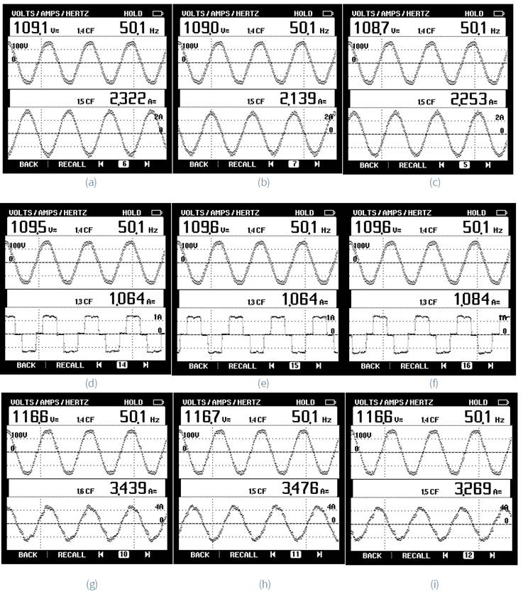
Figure 18 Steady state response of grid connected WECS. (a)-(c) grid voltage and current of three phases, (d)-(f) load voltage and current of three phases, (g)-(h) WECS voltage and current of three phases.

7. Conclusions
In this work, an adaptive filtering-based fuzzy logic control is implemented in grid connected PMSG driven wind energy conversion system. This algorithm does not require sensors for wind speed measurement or prior knowledge of the system parameters for maximum power point tracking. The main advantages of the proposed algorithm are the high accuracy and the fast-transient performance, since on-line updating of the scaling factors of fuzzy logic control is carried out by CMPN filtering. The performance of the developed control is analyzed with linear and nonlinear loads by considering the change the variation in wind speed. The simulation results are presented for maximum power tracking and the performance is compared with optimum torque control and it is claimed that the power coefficient remains at optimum value and power output of the system is increased with minimum response time. The results prove that the grid side control improves the power quality of the grid by injecting reactive power requirements of the load with a grid current THD of 2.2%.

