


 nueva página del texto (beta)
 Inglés (pdf)
 Artículo en XML
 Referencias del artículo
 Enviar artículo por email
 Citado por SciELO
  Similares en
SciELO
Similares en
SciELO 
 Permalink
1. Introduction
The need to move materials from one point to another in the supply chain, especially in the automotive sector, requires the creation of containers or devices that allow the parts to be moved while preserving their quality [1]. Additionally, such a way avoids damage generated by the movement during handling, such as impacts, vibrations, falls, dirt, and heels [2]. In terms of the car lights, an internal report considers that within a six-month period, 7.76% of the car lights experienced failures associated with parcel handling. Such damages correspond to a loss of $2609.71 USD.
A way to counteract damage is creating fastening means for the pieces that prevent inappropriate movements that harm the material. These fastening means are commonly known as inserts or inner packing for packaging in the automotive industry's supply chain [3, 4]. These elements make up a shape with a specific geometry and different materials with varying mechanical properties, such as compression, bending, toughness, roughness, and thermal conditions. These properties are chosen based on the type of product that will be stored and where the product will be physically located, such as warehouses, factories, seaports, or points of sale [5]. The design of the elements corresponds to suit the product and the conditions where it will be stored or moved [6].
The packaging inserts are manufactured using conventional methods such as plastic injection or material detachment machining. However, these methods have limitations regarding shapes, geometries, and materials, increasing costs and manufacturing times and potentially leading to a higher margin of clamping failure.
In this context, additive manufacturing, mainly 3D printing, emerges as the most advantageous method. It enables the production of customized inserts with the desired freedom in form. Unlike conventional manufacturing, where the cost increases with each unique piece, 3D printing allows for cost-effective production regardless of the variation in design [7]. Although this technology is still relatively new, the growing demand for free-form enclosures is expected to increase its adoption over time. Consequently, the wider usage of 3D printing will likely lead to lower prices and broader industrial applications [1-3].
This research aims to numerically simulate the finite element analysis for an insert used in packaging automotive headlights. The chosen method for producing the insert material is fused deposition melting (FDM) technology. This method was selected due to its cost-effectiveness and efficiency in production time, making it the most suitable choice. In contrast, conventional manufacturing methods such as plastic injection or material detachment are currently used for producing packaging inserts. However, these methods limit shapes, geometries, and materials, resulting in higher manufacturing costs, longer production times, and potentially increased clamping failure margins. Given these limitations, additive manufacturing, specifically 3D printing, offers the most advantages as it enables the production of unique inserts with the desired freedom in design.
1.1 Packaging
The main roles of packaging in the supply chain are protection, containment, and preservation. In addition to these traditional functions, there is a growing awareness of the benefits of more efficient and environmentally friendly packaging [2, 4]. From both financial and sustainable perspectives, efficient packaging leads to a more efficient supply chain. Reducing packaging materials is one of the representative efforts which improves environmental performance and reduces operational costs. Furthermore, due to recent legislative changes regarding packaging and packaging waste, many firms must reconsider their use of packaging [5]. According to the International Trade Center UNCTAD/WTO [8], packaging has four essential functions:
Each package and each part of the package must fulfill these four essential functions as economically as possible. The first three functions support structural design, while the last relates to the graphical method.
The packaging materials that protect fragile items, such as electronics and glass, are crucial and require careful design and production [8]. These materials should have excellent cushioning properties to effectively protect the packaged products while having a low density to reduce transportation costs, good barrier properties to prevent moisture, and good processability for proper buffering. The most crucial factor in selecting cushioning packaging materials is their ability to absorb impact energy and control impact acceleration within the range of product fragility. Additionally, using less design material, the packaging must provide efficient cushioning to absorb shock energy. Plastic foams and polystyrene, which are non-biodegradable and have high transportation costs, make up most of the protective and cushioning packaging materials and pose significant disposal problems [9]. Therefore, the demand for sustainable and biodegradable cushioning materials has arisen, prompting the creation of engineered cellular materials with defined shapes, sizes, and densities using 3D printing technology [10]. Lattice structures made from these materials are efficient and superior energy-absorbing materials with the potential for scale-up in engineering applications [11, 12], [13]. For example, researchers have demonstrated the acoustic absorption capability of poly (lactic acid) foams with various cell sizes and distributions produced using 3D printing technology [14, 15]. One essential point to consider is the mechanical properties of the 3D-printed parts. The mechanical properties of 3D printed components can vary depending on several factors, including the printing technology, material used, design of the piece, and post-processing techniques employed.
Some common mechanical properties of 3D-printed parts that are important to consider [16-18]:
Strength refers to the maximum load or stresses a 3D-printed part can withstand before breaking. It is influenced by the material used, printing orientation, infill density, and layer thickness.
Stiffness: This refers to the ability of a 3D-printed part to resist deformation under an applied load which is influenced by the material used and the part's geometry.
Toughness: This refers to the ability of a 3D-printed part to absorb energy before fracturing. It is influenced by the material used and the printing parameters.
Fatigue resistance: This refers to the ability of a 3D-printed part to withstand repeated loading over time. It is influenced by the material used, printing orientation, infill density, and post-processing techniques employed.
Creep resistance: This refers to the ability of a 3D-printed part to resist deformation under a constant load over time. It is influenced by the material used and the printing parameters.
Considering these mechanical properties while designing 3D-printed parts for specific applications is essential. Additionally, conducting testing and analysis can determine the mechanical properties of a 3D-printed part and optimize its performance. [15, 16].
1.2. Inserts
The insert is the component that reinforces the packaging since it must protect the product from impacts and vibrations and return to its original shape to provide greater cushioning. Notwithstanding, the most used inserts are usually made of expanded polystyrene or plastic; the industry employs many materials, e.g., air encapsulations, a packaging material of air bubbles enclosed between two polyethylene sheets [2]. This process allows the encapsulated air to provide a cushion to protect against shock. Other inserts like FOAM (Polyethylene) sheets are lightweight, soft, and resilient foam with excellent surface protection and cushioning properties [3, 4].
Other protective packaging materials are FOAM expanded, formed by a chemical mixture that expands into foam and generates a protective mold around the content or product. Foam-in-place creates a mold around the part supporting corners protecting the edges and helping with cushioning. Finally, Kraft paper (not newspaper or newsprint) is wrapped and crumpled to fill the space within a package, providing rigidity and cushioning [2, 5].
1.3. Additive manufacturing processes
The norm ISO/ASTM52900-15 is a standard for additive manufacturing (AM) [19], which provides a standard set of terminology, process principles, and process control methodologies for the AM industry. The primary purpose of this norm is to establish a foundation for communication and understanding between stakeholders in the AM industry, including designers, manufacturers, researchers, and regulators [19].
The norm ISO/ASTM52900-15 provides a comprehensive framework for the entire AM process, including design, materials, process parameters, post-processing, testing, and quality control. Additionally, it includes guidelines for process characterization, validation, and verification, as well as requirements for documentation and traceability. The norm also defines key terms and concepts used in AM, such as layer thickness, build orientation, and build platform.
The norm ISO/ASTM52900-15 is intended to promote standardization and consistency in the AM industry, which can help improve quality, reduce costs, and accelerate the adoption of AM technology. In addition, by providing a common language and a shared understanding of AM processes, this norm can help facilitate collaboration and innovation in the industry while ensuring safety and regulatory compliance. For example, according to the ISO/ASTM52900-15 concerning the additive manufacturing process categorization standard, there are seven additive manufacturing processes, which are listed in Table 1 [20]:
Table 1 Most common additive manufacturing processes.
| ADDITIVE MANUFACTURING PROCESSES | ADDITIVE MANUFACTURING PROCESSES DESCRIPTION |
|---|---|
| Binder Jetting | Using powder materials by using a liquid binder to stick them together layer by layer. The binder is sprayed from a printer head that moves over the powder bed, like an inkjet printer. The powder can be metal, ceramic, sand or composite. |
| DED (Directed Energy Deposition) | Melting metal materials by using a laser or an electron beam to melt them and deposit them on a surface, layer by layer. The metal materials can be in the form of powder or wire. The nozzle that sprays the metal can move in different directions. |
| Material Extrusion | Plastic or other materials that can be melted and pushed through a nozzle. The nozzle moves over a platform and deposits the material in thin layers, one on top of another. The material hardens as it cools down, forming the shape of the object. Material extrusion is also known as fused filament fabrication (FFF) or fused deposition modeling (FDM). Material extrusion can make simple and cheap parts that are useful for prototyping or hobby projects. |
| Material Jetting | Liquid materials are sprayed from tiny nozzles and solidified by light or heat. The nozzles move over a platform and deposit the material in thin layers, one on top of another. The material can be photopolymer, metal or wax. Material jetting can make high-resolution and multi-material parts that are useful for prototyping or casting. |
| Powder Bed Fusion | By using metal or plastic powders that are melted and fused by a heat source, such as a laser or an electron beam. The heat source moves over a platform and scans the cross-section of the object, layer by layer. The powder acts as a support material and is removed after the object is finishe. |
| Sheet Lamination | Method that builds an object by stacking and cutting thin sheets of material. |
| Vat Photopolymerization | A container is filled with a special liquid that can turn solid when a shine light on it to make a 3D object out of this liquid. Using a machine that can control the light and make it follow the shape of the object. The machine moves the light over the liquid, and wherever the light touches, the liquid becomes solid. The machine does this over and over again, making thin layers of solid material on top of each other, until your object is complete. |
1.4. Numerical Simulation FEA
The Finite Element Analysis (FEA) is the simulation of any given physical phenomenon using the numerical technique called the finite element method. The FEA software reduces the number of physical prototypes and experiments and optimizes components in their design phase to develop better products faster while saving on expenses [21]. Using mathematics to understand and quantify any physical phenomena comprehensively is necessary. The development of FEA has been driven by the desire for more accurate design computations in more complex situations, allowing improvements in design procedures and products [21, 22].
1.5. FEA and 3D printing integration
Computer simulation tools have become increasingly popular in recent years to evaluate and improve various processes, including many for manufacturing applications. In particular, 3D printing technology with advanced simulation tools has enabled engineers to bring virtual designs to life in physical reality, providing a powerful new tool for innovation and design optimization [23, 24]. Advanced digital simulation tools can subject prototypes or test parts created through 3D printing to various simulated operating conditions, for example. By fine-tuning the design using this iterative process, engineers can identify and correct potential design flaws or performance issues before the product is manufactured [25-27]. In addition to improving the design and performance of existing products, 3D printing and advanced simulation tools are also facilitating the creation of entirely new applications. For example, researchers have used these tools to develop complex micro-scale structures and devices with unique functionalities, such as bio-inspired materials, sensors, and actuators [28-30]. Integrating 3D printing and advanced simulation tools provides a powerful new approach to engineering design that drives innovation and enhances the final quality of many products in various industries, including aerospace, automotive, medical, and consumer goods [31]. As these technologies evolve and become more widely adopted, their potential applications will likely continue expanding, and artificial intelligence methodologies like machine learning and neural network algorithms [32-35].
2. Methodology
This study fabricated the insert using the Fused Deposition Modeling (FDM) process. A thermoplastic polyurethane (TPU) filament was chosen for its mechanical properties, specifically its ability to withstand elongation and tension, essential for withstanding the product's strains during transportation. Additionally, TPU's flexibility allows it to grip the pieces securely without causing any damage. The finite element analysis was performed using SolidWorks software [36].
2.1 3D Printer Characteristics
Regarding the manufacturing of the insert, an Artillery Genius Pro model printer was used in this research. The dimensions of the print volume are 220 x 220 x 250 mm. It has a heated bed that increases its room temperature from 0° to 120 ℃ in 3 minutes and supports flexible materials. In addition, it has a tempered glass platform and double-driving screw, allowing a more stable printing with high precision and speed movement.
2.2 3D Printing Filament Properties
The filament for the 3D printer used in this research is from Amazon Basics with a diameter of 1.75 mm + / - .05 mm; black color; the spool contains 1 Kg of filament. The material corresponds to thermoplastic polyurethane (TPU), with high tensile strength (26 MPa) and high flexibility (4.3 MPa), and resists oil, grease, and scratches; It stands up well to more rigorous wear.
2.3 Insert Design
The designed insert in this study is circular, making it easy to adapt to the profile of the automotive headlight. The insert consists of two concentric circles, one with a diameter of 20 cm and the other with a diameter of 15 cm, with a thickness of 1 cm. It is joined by 27 flexible radii that serve as support, counteracting the loads on the piece (refer to Fig. 1 for details). Notably, the insert's design was inspired by the project entitled "Theoretical Study of the Heterogeneity of Forces in Airless Tires Made with Elastic Polyurethanes" [37], which features a structure for an airless tire that served as the basis for the insert design.
2.4 Finite Element Analysis
The insert is designed to contain a lighthouse, and the stowage process involves gradually placing weight on top of the cardboard box. This weight will create the modules of material that will be transferred as the final product. Given the above, the boundary conditions for this analysis will be a fixed support point in the lower part of the insert, another fixed support point inside the insert that will simulate the part inside it, and a compression point load in the upper part. The compression load will be 50 Kg (500 N); this is the product of the sum of the load of the weight of 5 lighthouses inside their packages with an approximate weight of 5 Kg each, plus the weight of a standard wooden pallet (1140 x 1180 x 160 mm) with an estimated weight of 25 Kg. Table 2 shows the mechanical properties of the TPU material used to print the insert for the numerical simulation.
Table 2 Mechanical properties of the TPU (thermoplastic polyurethane) filament.
| Property | Value | Unit |
|---|---|---|
| Elastic Modulus | 26000000 | N/m2 |
| Poisson Coefficient | 0.45 | N/D |
| Shear Modulus | 318900000 | N/m2 |
| Density | 1250 | Kg/m3 |
| Tensile limit | 1500000000 | N/m2 |
| Elastic limit | 39000000 | N/m2 |
2.4.1 Finite Element Mesh Properties
Several meshing proposals were made until a calculation was completed and produced a result that enabled the observation of the areas reaching maximum stress and the displacements of the piece, which can validate the design's viability for the intended work. The latest was achieved with a medium-density mesh with the characteristics: of solid-type mesh, based on curvature, with four Jacobian points, with a quality of high-order quadratic elements of 2.12 mm and a ratio of 1.5. It has 20022 nodes and 9349 elements (see Fig. 2). Two more mesh iterations were performed to confirm the result with the mentioned characteristics. However, changing the size of the quadratic elements to 50% smaller and more significant, respectively, than the current size, therefore, changing the mesh density to a thicker one and another thinner.
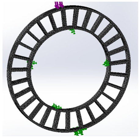
Figure 1 The location of boundary conditions is depicted, including the support points represented in green and the compression point load in purple, along with the corresponding mesh.
Table 3. summarizes the characteristics and the convergence results obtained for the three meshes studied.
2.5 3D printer characteristics and parameters
As previously mentioned, choosing the appropriate 3D printer parameters is critical for achieving optimal results. In this case, the piece was printed at 40 mm/second speed, using an extruder temperature of 220°C and a hotbed temperature of 30°C. These settings were carefully selected to ensure proper adhesion between the layers and prevent warping, resulting in a high-quality print. Additionally, a 100% material infill grid pattern was utilized. Fig. 2 illustrates the 3D-printed packaging insert.

3. Results and Discussions
The finite element simulation analysis provides valuable insights into the bending behavior of the insert and its ability to withstand compression stress. The results indicate that the insert experiences bending primarily in the surrounding areas near the applied load but does not reach a breaking point. This finding suggests that the insert is structurally sound and can handle the forces it is subjected.
In Fig. 3a, the maximum pressure value is reported to be 4.59 MPa at the section where the load is applied. This information helps to quantify the magnitude of the compression stress experienced by the insert. It would be beneficial to compare this value with the known strength limits of the insert material to ensure that it operates within a safe range. Fig. 3b here, it is presented the three coordinates analyzed: 1) Located x=94.5, y=2.81, z=10 mm, with a force of 4.59x10⁶ MPa; 2) Located X=94.5, Y=2.81, Z=1.67 mm with a force of 4.20x10⁶ MPa; 3) Located X=94.5, Y=2.81, C=1.67 mm with a force of 4.62x10⁶ MPa. Only the two nodes at the edge were over the maximum admissible for the TPU; however, their impact was insufficient to take the whole insert to the plastic or cadence state.
A closer examination was conducted on the specific zone of interest to evaluate the insert's response to the applied pressure. Fig. 4 illustrates the minimal cadence observed in this area, indicating that the insert reacts promptly to the applied pressure. This responsiveness is an essential factor to consider, as it demonstrates that the insert can quickly adapt to external forces and distribute them effectively.
The displacement analysis reveals no significant inconveniences or risks associated with executing the intended work for which the insert was designed. The calculated displacement for the section under consideration is approximately 5.75 mm, while each radius measured 28.5 mm. This comparison indicates a sufficient displacement margin, suggesting that the observed movement does not harm the insert or the transported piece. Fig. 4 visually represents this observation.
Based on the numerical simulation, it can be concluded that the insert's design, material, and dimensions can withstand the expected compression load. It is important to note that each headlight will utilize two inserts per piece, one for each end (left side and right side). Therefore, the compressive strength demonstrated by each insert would be proportionally higher than the values presented in the results, considering the load distribution across multiple inserts. This redundancy adds confidence in the insert's ability to handle the intended load.
Overall, the finite element simulation provides strong evidence that the insert is well-suited for its intended purpose. The bending behavior, compression stress, prompt reaction, and displacement analysis demonstrate that the insert's structural integrity is maintained and can effectively withstand the anticipated loads.
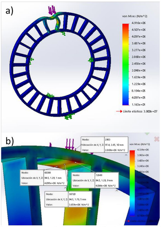
Figure 3 (a) The numerically simulated forces in the insert show that the piece would be bending, returning to its normal position once the load is removed, without any significant risk of collapse. (b)
The three coordinates analyzed: 1) Located x=94.5, y=2.81, z=10 mm, with a force of 4.59x10⁶ MPa; 2) Located X=94.5, Y=2.81, Z=1.67 mm with a force of 4.20x10⁶ MPa; 3) Located X=94.5, Y=2.81, C=1.67 mm with a force of 4.62x10⁶ MPa.

4. Conclusions
The design of the 3D-printed packaging insert was validated by conducting a finite element analysis to ensure its functionality under the expected loads. It was possible to reproduce the proposed insert design and material through 3D printing. Fused filament modeling was used as an additional method for manufacturing packaging inserts, in addition to traditional material detachment processes.
However, it is essential to note that finite element analysis alone may not be sufficient for calculating dynamic load phenomena, such as impacts or vibrations. For such phenomena, software that can calculate nonlinear behaviors is required. Therefore, a complete computer-assisted analysis would be necessary to validate such activities.
The use of additive manufacturing for creating inserts allows for more flexibility in design, better adaptation to the parts according to the application, and optimization of manufacturing times, material amounts, and costs. The next step in this research would be to explore new possibilities for using unique designs, new materials, and other additive manufacturing technologies to adapt these inserts more widely in both the automotive and non-automotive industries.
The main findings of this research include the successful reproduction of the proposed insert design and material through 3D printing and the potential benefits of additive manufacturing in terms of flexibility, adaptation, and optimization of manufacturing processes:
1) The numerical simulation allows realizing that the weight mainly impacts the receiving zone of the insert
2) There are zones above the elastic limit of the TPU (3.9x10⁶ MPa), but it is minimal, which does not represent a considerable risk for the insert
3) Virtual testing regarding FEA can be done to have visibility of the previous manufacture and use of inserts for packing
4) It is possible to generate inserts using additive manufacturing, specifically by FDM technology
5) The TPU has proven to be an ideal material to accomplish this task due to its mechanical properties as exceptional tear resistance, hardness, and elongation

