1. Introduction
It is commonly known that under the action of cyclic stresses in metals and alloys, cracks appear and gradually develop, ultimately causing destruction. Such processes of gradual accumulation of damage under the influence of cyclic loads are called fatigue. Fatigue fractures are especially dangerous in that they can develop under the action of stresses that are much lower than the ultimate strength and yield strength (Borisov et al., 1987; Stepnov, 1985; Suleimenov et al., 2022). It is noted that more than 80% of all cases of operational failure occurs as a result of cyclic loading (Bekbauov et al., 2017; Korzhyk et al., 2021; Lei et al., 2021). Due to the long duration, and, consequently, the high cost, fatigue tests to determine the endurance limit of samples are often carried out not until destruction, but for the determination of operating time, a certain test base NB. In this case, the pieces that have passed the test without destruction are tested again at higher levels of vibration stresses (Grigorenko et al., 2020; Kunanbayeva et al., 2022; Mukhambetzhanov & Baishemirov, 2013). As a rule, when conducting regression analysis of test results, specimens that failed during test with operating time corresponding to NB are taken into account.
In linear regression analysis to establish the relationship between stress and durability, it is necessary to transform the values in order to represent the equation of the fatigue curve as a linear relationship between the converted values (Borisov & Korzhyk, 1998; Gates & Fatemi, 2017). The following is usually taken as a random variable: y = lgN, since it is in this case that the normal distribution law underlying the regression analysis is satisfactory. The transformed value x = F(σa) is selected as an independent value. The form of the function x = F(σa) is set so that the dependence y = f(x) is linear (Kvasnytskyi et al., 2020; Razavi et al., 2020; Shojaei & Volgers, 2017). The fatigue curve equation has the form:
where: x = lgσ; y = lgN; a and b - fatigue curve parameters.
With an insufficient amount of fatigue tests, the parameters of Equation (1) are determined on the basis of regression analysis, the equation of the averaged fatigue curve corresponding to the fracture probability P = 0.5 is established. With a sufficient amount of testing, a family of curves can be constructed for a number of fixed levels of fracture probabilities (Kunitskii et al., 1988, 1990; Panfilov et al., 2020; Rege et al., 2019). For the experiments, an alloy of technical titanium was used, intended for the manufacture of products with high strength with sufficient plasticity and toughness, high resistance and small plastic deformations, brittle and fatigue fracture. Authors used flat specimens with a working part length and width of 100 mm and 200 mm, respectively. The thickness of the plates was 2 mm. The alloy under consideration is used in mechanical engineering, instrument manufacture and the tool industry. The chemical composition of the alloy and its physicomechanical characteristics are presented in the Table 1.
Table 1 Chemical composition and physicomechanical characteristics of titanium alloy.
| Chemical composition of Titanium alloy | |||||||
|---|---|---|---|---|---|---|---|
| Element | Ti | Al | Fe | O | Si | C | Other impurities |
| Mass fraction, % | 99.3 | 0.18 | 0.17 | 0.15 | 0.08 | 0.06 | 0.06 |
| Physicomechanical characteristics | |||||||
| Characteristics | E | σB | δB | HB | |||
| Value | 1.1 GPa | 410 MPa | 26% | 150 MPa | |||
Note: E - elasticity modulus; σB - tensile strength; σB - relative elongation at break; HB - Brinell hardness.
The purpose of the article is to describe the use of the hypothesis of linear damage summation when processing the results of fatigue tests. The objectives of the research are to determine the endurance limit of high strength material, as well as a mathematical measurement of the expected destruction.
2. Materials and methods
Fatigue tests of the pieces were carried out by the well-known methods (Korzhik, 1992c; Stepnov, 1985) on an electrodynamic shaker at normal temperature with cantilever mounting of the test piece (Figure 1). It is known that the work of external forces applied in the process of elastic deformation is conserved as some energy, which then restores the element after the stress is removed. However, when a crack appears in the material, the amount of elastic energy changes. If the elastic strain energy of a plate without a crack at a given stress level is equal to U0, then in the presence of a crack it will be determined by the equation (Stepnov, 1985; Syrmanova et al., 2021):
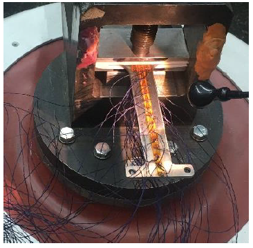
Figure 1 Photo of an electrodynamic shaker with a restrained test piece with strain gauges attached.
where: E - elasticity modulus of the material; the component
This expression was obtained under the assumption that in the presence of a crack of size 2a in the plate, the elastic energy of deformation is absent in the volume of the material equal to
Indeed, the results of the study showed that at a stress level of σ 0 = 200 MPa along bending and torsional forms, crack formation processes were detected in the materials under study. At the same time, at the moment of the appearance of a crack in the specimen, a decrease in the frequency of natural vibrations by 3% was noted. Next, the fatigue curves for various fracture probabilities were analysed (Figure 2).
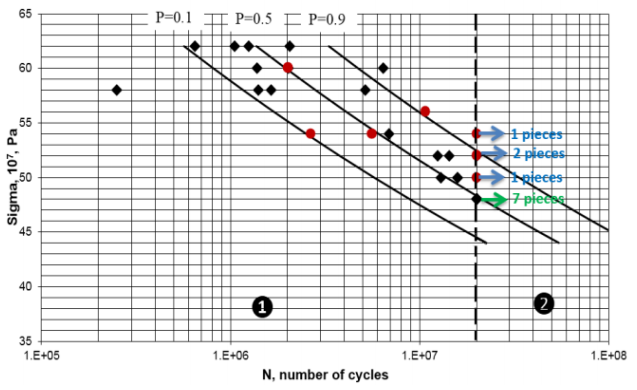
Note: 1 - zone of failed test piece; 2 - zone of passed test piece; - ⧫ pieces that failed at the one load level; • - pieces that passed several load levels until the number of cycles to fracture was determined and then collapsed. Arrows indicate non-destroyed specimens.
Figure 2 Fatigue curves for different fracture probabilities P (0.1; 0.5; 0.9).
For the endurance limit, a level of vibration stresses was taken at which from 6 to 8 pieces passed (Antolovich & Armstrong, 2014; Stanzl-Tschegg, 2014). As can be seen from Figure 3, with the previously used approach to processing the results of fatigue tests, the endurance limit (based on 7 samples) practically lies on the fatigue curve with a fracture probability P = 0.5.
3. Results and discussion
In the present study, the authors have carried out mechanical tests of materials for high-cycle fatigue with the number of load cycles up to 106-108. The amplitude for this type of test was selected in such a way that the material deformation occurred only in the elastic zone, and the stresses were less than the proportional elastic limit. The results of the study showed that the fatigue fracture observed in experiments has a complex development and depends on several factors (in this case, the composition and structure of the material, the load characteristics). The test data will be processed in 3 stages. At the first stage a regression analysis will be carried out, using only the durability at which the specimen fractured, the resulting fatigue curves are shown in the Figure 3.
The points corresponding to the specimens tested at several load levels are highlighted in red; only the last level at which the failure occurred is considered. The green dots corresponding to the endurance limit are not included in the analysis. At each i-th load level, after the number of cycles n i , a certain fraction of fatigue damage ∆D i was accumulated. Assume that the degree of breakdown is the same for all load levels and for each level of vibration stresses there is a limiting number of cycles-durability N i > n i , at which a crack (fracture) is likely to occur in the test piece (Borisov et al., 1986; Debroy et al., 2018; Kumar et al., 2017), then the damage accumulated at the level vibration stress σ i is defined as:
At the final k-th the load level with the number of cycles n k , a crack was formed in the test piece, which means that in accordance with the principle of linear damage summation, the damaging of the specimen accumulated at all levels reached its limiting value, taken equal to unity:
To consider the fraction of accumulated damage at the load level passed by the specimen, Equation (1) is used, where the durability logarithm Ni is determined by the following equations:
where: (Y i )0.9 - the number of cycles corresponding to the quantile fatigue curve for the fracture probability P = 0.9 at the stress level σ i ; s - a constant (yet unknown) coefficient for all load levels of a given test piece.
The coefficient s is determined by substituting Equation (5) into (4):
where: n 1 - the number of cycles at the first (lower) stress level σ 1 exceeding the material endurance limit, i.e., σ 1>σ -1; n k n k = N k (failure at the k-th level), whence it follows the value:
The second stage includes the determination of a certain equivalent durability (N eq III), to determine which the Equation (6) is used, presenting it in a slightly different form:
where: ∆n 1 - the number of cycles that the specimen would pass at the first level of vibration stresses before the cracks formation.
Equation (8) implies:
The third stage is carried out similarly to the first, with the replacement of the fatigue values for those obtained in the second stage, as well as with the exclusion of points with stress levels below the endurance limit (Hryhorenko et al., 2020; Liu et al., 2019; Zhurinov et al., 2020). The results of the regression analysis obtained during the third stage are shown in Figure 4. Test pieces for which the durability was recalculated are indicated by red dots. Thus, it turns out that the endurance limit σ- 1 = 480 MPa, determined from 7 undestroyed specimens, lies much closer to the fatigue curve with a fracture probability P = 0.1. And with the probability of survival P = 0.9 based on tests N= 2•107 cycles, the level of vibration stresses corresponds to σ-1 = 470 MPa.
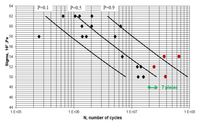
Figure 4 Fatigue curves for different fracture probabilities P (0.1; 0.5; 0.9) after linear damage summation.
To check the distribution of stresses in the sample and determine the localization of fractures, a calculation was performed for natural frequencies and modes of vibration with the determination of relative stresses in the samples using the ANSYS software package (Figure 5)..
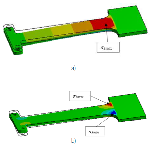
Note: a - when bending vibrations with a frequency f 1= 213 Hz; b - when torsional vibrations with a frequency f 2 = 1515 Hz.
Figure 5 Relative stress values for titanium alloy.
The simulation results made it possible to determine the places of localization of the maximum mechanical stresses arising under the considered loads and the loading scheme. Therefore, one should expect the occurrence of cracks in the regions with σ max, (the regions in Figure 6 are highlighted in red). This is confirmed by the experiment, the results of which are shown in Figures 6, 7.
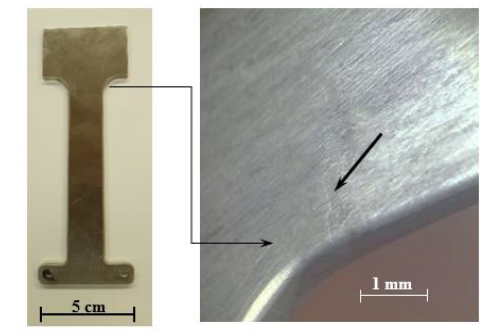
Note: a - photo of the specimen; b - photograph of a sample section with a crack.
Figure 6 Failure of titanium alloy specimens after fatigue tests at resonant frequencies during bending vibrations.
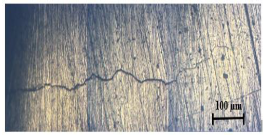
Figure 7 Micrograph of a crack after fatigue tests of a titanium alloy based on tests N = 2·107 cycles with a vibration stress level σ -1 = 470 МРа.
The mechanism of fatigue fracture is largely associated with the inhomogeneity of the real structure of materials (difference in size, shape, orientation of adjacent metal grains) (Baishemirov et al., 2020; Chong et al., 2021; Grigorenko et al., 2019). The formation of cracks in the experiments began from the edge regions, which was confirmed by the results of scanning electron microscopic studies (Figure 8).
4. Conclusions
The presented results give grounds to conclude that the use of the hypothesis of linear summation of damages when processing the results of fatigue tests gives a satisfactory for practice accuracy of calculating the material fatigue limit. Thus, the results of the study showed that the hypothesis of linear damage summation is applicable for the material considered in question. From the analysis of the fatigue curves of the titanium alloy, it is shown that fracture occurs when the sample damage accumulated at all levels reaches its limiting value.
Also, the study did not reveal the effect of the sequence of stress and the loading history on the material durability. Experiments have shown that, as expected, a feature of the fracture process under cyclic loading is the appearance of microcracks in the material (long before fracture). Such microcracks were formed on the surface of the material where the change of the shape took place.


 nueva página del texto (beta)


