


Servicios Personalizados
Revista
Articulo
 texto en
  Artículo en XML
 Referencias del artículo
 Enviar artículo por email
Indicadores
-
 Citado por SciELO
 -
 Accesos
Links relacionados
-
 Similares en
SciELO
Similares en
SciELO
Compartir

 Permalink
Revista mexicana de ciencias agrícolas
versión impresa ISSN 2007-0934
Rev. Mex. Cienc. Agríc vol.6 no.8 Texcoco nov./dic. 2015
Articles
Design, construction and evaluation of a solar tracking system for a photovoltaic panel
1Colegio de Postgraduados. Carretera México-Texcoco km 35.5, C. P. 56230, Montecillo, Texcoco, Estado de México. Tel: 01 55 58045900 Ext. 1383. (arreola.rubisel@ colpos.mx; mcastro@colpos.mx; sdgsgs@colpos.mx).
2Instituto Internacional en Biosistemas Sustentables A. C. Calle 16 de septiembre 9b. C. P. 56208 San Miguel Tocuila, Texcoco, Estado de México. Tel: 01 595 9549802. (toxic_drm@hotmail.com).
Among the renewable energy sources, solar energy is the most important, because of its abundance, sustainability and is completely free of charge. Besides, using a solar collector tracking the total energy received on a clear day can be about 30-45% higher than for the same solar collector static. We designed and built a system of autonomous and able to follow the movement of the sun, which was coupled to a photovoltaic panel to improve efficiency in energy capture tracking. Device performance was evaluated in terms of energy, three evaluation tests programming it to be oriented to the sun every 60, 30 and 5 min, and the results were compared with the energy efficiency of a fixed photovoltaic panel. The software was developed for the entire territory of Mexico and throughout the year. The best energy performance is obtained when the solar tracker is oriented to the sun every 60 min, the energy generated was 27.98% compared to the fixed panel, with an energy expenditure for operation of 1.3% of final energy gain. Comparing energy production system with the global solar radiation (ISR), usuing 13.27% of the available energy, and 2.93% on the fixed panel.
Keywords: photovoltaics; solar energy; solar tracker; microcontroller; two-axis tracking
Entre las fuentes de energías renovables, la energía solar es la más importante, debido a su abundancia, sostenibilidad y completamente libre de costo. Además utilizando un colector solar con seguimiento, la energía total recibida en un día claro puede ser del orden de un 30-45% mayor que para el mismo colector solar estático. Se diseñó y construyó un sistema de seguimiento autónomo y capaz de seguir el movimiento de sol, el cual se acoplo a un panel fotovoltaico para mejorar la eficiencia en la captura de energía. Se evaluó el funcionamiento del dispositivo en términos energéticos, se realizaron tres pruebas de evaluación programándolo para que se oriente al sol a cada 60, 30 y 5 min, y se compararon los resultados con el rendimiento energético de un panel fotovoltaico fijo. El software desarrollado fue funcional para la totalidad del territorio de la República Mexicana y durante todo el año. El mejor rendimiento energético se obtuvo cuando el seguidor solar se orientó al sol cada 60 min, la energía generada fue de 27.98% más respecto al panel fijo, con un gasto energético para su funcionamiento de 1.3% de la ganancia final de energía. Comparando la producción de energía del sistema con la radiación solar global (ISR, por sus siglas en ingles), éste aprovecho 13.27% de la energía disponible, y 2.93% más respecto al panel fijo.
Palabras clave: energía solar; energía fotovoltaica; microcontrolador; seguidor solar; seguimiento en dos ejes
Introduction
In the global context, according to the model proposed by Chefurka (2007), fossil fuels provide most of the flow composition of global energy, but decline rapidly during the second half of the century. It is expected that at the end of the century, the contribution of oil and gas is almost zero, and the key players are, in order, hydropower, renewables, coal and nuclear energy.
The importance can acquire non-conventional energy in Mexico is noted for example, if we consider that there are 190 432 towns with less than 5 000 inhabitants, of which 6.9% (13 140 seats) do not have electricity in the country, which represents a population of approximately 2 236 295 people without this service (INEGI, 2010).
Among the renewable energy sources, solar energy is the most important, because of its abundance and sustainability. Regardless of the flash of sunlight, solar energy is widely available and completely free of charge (Kroposki and DeBlasio, 2000).
Photovoltaic systems (PV), are solar energy systems are that produce electricity directly from sunlight, they produce clean, reliable energy without consuming fossil fuels and can be used in a wide range of applications (Castellanos and Escobedo, 1980).
The systems use of solar energy should collect as much energy received at a particular place, this condition requires that the collecting surface is at all times perpendicular to the sun and therefore can only optimum collection achieved if said surface is provided with a sun-tracking movement (López, 1985) .Using a collector tracked, the total energy received on a clear day can be about 35% higher than for the same static collector (Mosher et al., 1977; López, 1985), or up to 40% (Naaijer, 1985).
The two most common orientations of a system that tracks the sun to get the best possible performance from solar radiation incident on a surface or specific point are on an axis to follow the sun from east to west and two axes guaranteeing always follow the sun directly. The two-shaft system is the best to maximize solar radiation at all times, this tracking system uses both direct and diffuse radiation (Madrid, 2009).
Abu-Khader et al. (2008) reported an overall increase of about 30-45% in power output for solar tracking system in north-south axis (NS), compared with a fixed PV system; also they found that the solar tracking the NS axis is optimal. Meanwhile Huang et al. (2011) found that on a sunny day a tracker of an axis can be obtained 35.6% more energy relative to a fixed PV system.
Kacira et al. (2004) experimentally investigated the effect of two-axis solar tracking gain in energy compared with fixed panel in Sanliurfa Turkey, and found that the average daily gain is 29.3% in solar radiation and 34.6% in power generation for a particular day in July.
Several methods have been proposed engineering for continuous sun tracking using single-axis trackers in open loop (Kalogirou, 1996), two axes closed loop (Lynch and Salameh, 1990) and two-axis open loop (Park et al., 1996). There are different drivers to implement control systems, for example, programmable array logic (PAL) (Abouzeid, 2001), programmable logic controller (PLC) (Abdallah and Nijmeh, 2004), PC (Yousef, 1999) and microprocessors (Koyuncu and Balasubramanian, 1991).
There are no references about the efficiency of solar trackers in Mexico, so the aim of this work was the design, construction and evaluation of a solar tracking system with two axles, implementing a microprocessor control system for a panel automated photovoltaic, functional for the entire Mexican territory.
Materials and methods
The research project was conducted in the Campus Montecillo of the Graduate College, located in the municipality of Texcoco, State of Mexico, which is in the 19° 27' 38" north latitude, west longitude 98° 54' 01" and elevation: 2 250 m. The incidence of solar radiation in the region is on average 5.5 kWh m-2 day-1 (Castellanos and Escobedo, 1980, SEI, 2007).
We designed and built a mechanical-electronic system to optimize the process of solar energy for conversion into electricity, guiding automatically solar panels toward higher incidence of radiation during the period August 2011 to November 2013 .The evaluation of the energy performance of the solar tracker was made 3.4 and 5 February 2014, they were completely clear days.
Design. According to the methodology proposed by Bastida and Rabelo (2009), is beginning with identifying a need that should be expressed as clearly and specifically as possible, as this makes it easier to define what the major problems we face in meeting this need. After defining the problems to be solved are proposed and define the systems and structures that make up the machine that will be designed to meet the basic need, which involves setting the basic role they will play, for which must perform a process of generation, evaluation and selection of alternatives. Then established sub-functions and principles of solution are chosen. Finally the final concept is described and proceeds to detail design.
Detailed design and construction. The detailed design was based on the need to specify full and detail the elements recommended for the manufacture of the product. At this stage, the final plans of the machine so it took into account the methods of design for assembly and manufacturing were obtained.
This stage allowed knowing the characteristics by calculation and dimensioning systems and components of the photovoltaic solar tracking device (DSSF). It was necessary to design some systems propose a criterion variables to use different equations to do the calculations required. Because of this we can see that the design is an iterative process that allows feedback and make modifications that are required, either by own restrictions for the design or manufacturing issues, aesthetics, safety standards, etc.
Assessment methodology. A box of sensors were built to measure the flow (Icc) on the output fixed and mobile panel, type ACS712 sensors (brand Allegro MicroSystems Inc., Massachusetts, USA). The sensors are calibrated by comparing the data obtained by a conventional multimeter FU0233 type (brand Fulgore) and a type CR1000 datalogger (Campbell Scientific brand, Utah, USA) to obtain the equations of operation of the sensors.
The DSSF was tested with three discrete time intervals every 5, 30 and 60 min programming, values of operating times of motors with a circuit data acquisition who joined the control were recorded, and the values measured with flow sensors recorded in the datalogger type CR1000, Campbell Scientific brand, Utah, USA, and the fixed reference panel is placed at an angle of 34° to the horizon.
For calculating the values of power generated by the panels (DSSF and fixed), the values were considered of constant voltage 22.3 V (VAC), as specified by the manufacturer of the solar panel.
Results and discussion
Then each of the components was designed for construction of photovoltaic solar tracking device as described (DSSF).
Supporting structures. The main support structures and solar panel are designed to provide structural strength to the tracker movement support systems and provide attachment points and grab them. Structural shapes of a material and appropriate dimensions were used, with assembly screws, high structural strength, high stability (low center of mass) and reasonable costs.
A supported by four steel legs 1018 equals 50.8 mm element PTR, which are foldable for better mobility was used for the construction of the main structure. Four pieces of PTR 25.4 mm were used to give tension to the legs of the main stand. A piece of 1018 steel slab of50.8 x 6.35 mm was designed to unite the four legs and permit displacement which produces the fold. For the union of all the parts we used screws, nuts and washers. To raise or lower the device as required, we used a profile made of steel PTR 44.45 mm.
Structure of the solar panel support. The support panel structure is constructed in the form of H, it rotated 90 degrees, an aluminum anodized type was used 40 E 8 40 x 40 x 40 mm profile. Profile partsjoined by elements shaped on aluminum L 38.1 x 38.1 mm, special screws and nuts.
Energy harvesting system. A solar panel DS-A1-45 (brand DASOL, Zhej iang, China), whose characteristics are shown in Table 1 was used.

A charge controller, ENESOL brand (State of Mexico, Mexico) was installed with a solar panel input and output for batteries and loads (electrical direct flow). Three batteries ENESOL brand (State of Mexico, Mexico) model A 12-12 (12 V and 12 Ah) were used for storing the electrical energy generated by the solar panel, for use for both solar tracker drive, to be connected other applications as well.
Motion control system. The control system serves for the movement values (angles) which determine the movement (azimuth and solar elevation) of the solar panel and the power stage by achieving the engine drive. The main requirement in which this system is based is the automatic positioning of the panel. It took into account the dimensions of the control box (cabinet) mainly have a low energy consumption and low construction costs. Figure 1 shows the components and connections of the control system.

Engines. For the horizontal and vertical movement of the panel, two engines were used, Model ERU-B2, Beijing Fenglong Greenhouse Technology Co. banrd (Beijing, China). The technical specifications of the engines indicated in Table 2.

Software. To determine the orientation (azimuth and solar elevation) panel through solar tracking system, the sun's motion was calculated about a point on the earth's surface, according to that algorithm proposed by Walraven (1978). The algorithm originally coded in FORTRAN programming language was converted to Visual Basic 6.0 language.
Various adjustments were made to the algorithm to calculate the movement of the sun from sunrise to sunset every day of the year. Settings include: determining leap years, the calculation of the day, activation of the DST, the adjustment of the azimuthal coordinates (N= S= 0° and 180°), the software generates only values of positive azimuth and elevation between dawn and sunset, among others. The application interface requires the following input data: year, time zone, latitude and longitude (in degrees, minutes and seconds). The implementation of this application generates a.txt extension.
The maximum and minimum lengths of Mexico were determined using the Google Eart software, are the following: 1) North: 32° 43' 6.49" north latitude and 114° 43' 16.44' west longitude; 2) South: 14° 32' 27.00" north latitude and 92° 13' 7.65" west longitude; 3) this: 21° 12' 5.86" north latitude and 86° 42' 36.99' west longitude; and 4) West: 29° 8' 46.87" N and 118° 27' 24.00' west longitude. Wityh the coordinates of limits and dates of equinoxes and solstices, the created program was implemented, and the results were compared with the software provided on the website "http://www.sunearthtools.com/" that also used the equations that were used to create the tables of the American Ephemeris and Nautical Almanac.
Control. A control device was developed to perform the following functions: collecting input data for the program, to perform the same calculation operations that the software to drive the motors that move the PV panel, show results and save them to a unit external USB storage. This device was called the control. The main components of control are: motherboard, microcontroller (PIC18F4553), matrix keyboard, display, clock, LEDs, power phase (2 bridges H electromechanical and an integrated circuit 2803 UNL), network terminal connector or RJ45, recorder USB connectors (4 pieces), plastic shell memories (Figure 2)
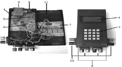
Figure 2 Open control (left) and closed (right), 1) motherboard; 2) micro-controller; 3) matrix keyboard; 4) display; 5) clock; 6) LEDs; 7) power stage; 8) terminal network connector; 9) USB memory recorder; 10) connectors; and 11) shell.
Turning and adapting the code in Visual Basic 6.0. programming language C, thpugh the PIC C Compiler software, to record it in the micro-controller with the PIC-PROG II software and, the device "charger/programmer module microcontrollers PICs to USB port". Since the microcontroller control has a processing capacity of 8 bits, there was an error of 0-3 degrees in the calculation of variable height and azimuth with respect to data from Visual Basic 6.0 with an operating system of 32 bits. The error was acceptable because it would not cause significant losses in energy capture.
Safety tops. Two switches were connected to the engine that was responsible for the solar elevation; to prevent the bar holding the rotating panel to move more than it should, causing breakdown or malfunction of elements on the control system and transmission system.
Breakers. It has a breaker system, MS116-10 type (brand ABB, Zurich, Switzerland) and two Breakers, WMZS2B07 type (brand EATON, Ohio, USA) to interrupt the flow of input and output of then control in order to performe maintenance and in this case, during the evaluation of solar tracking system.
Transmission system. This system serves to transmit the power of each of the engines to the drive gears of the solar panel support, for movement according to the requirements. For the design of the system were taken into account: automatic positioning, the corresponding dimensions, structural soundness and economic viability.
A transmission ratio was designed so that for each second, of the engine 1.02 degrees of rotation of the panel are obtained (Figure 3).

Description of the final concept. The final concept of the solar tracker called photovoltaic solar tracking device (DSSF) (Figure 4), takes into account virtually all major requirements and essential problems encountered in the design methodology. The DSSF consists of three systems, a subsystem, and two support structures. The main structure will support all systems and structures. Holding the box (cabinet) of the motion control system, then on the top was coupled the transmission system, which in turn supports and movements of the support structure of the panel, and finally, the feedback system and energy storage is distributed primarily in the structure of the panel support and motion box of the control the system.

It's noteworthy that, the measurement subsystem of the captured energy is related to the energy harvesting system and storage, which is also included in the box of the control system. Another important point is that the engines of the motion control system will be supported by the transmission system. So the DSSF cannot be regarded as separate parts, but as a general system.
Energy evaluation. The following comparisons are presented in terms of efficiency DSSF with fixed photovoltaic panel in all cases. The first noted that between 11:00 and 14:00 the curves energy collection panels with tracker and fixed do approach (Figure 5). The results are consistent with those reported by Gonzáles (2006), who reported that during the hours around solar noon, the curves of energy production and a fixed panel tracker also approach.
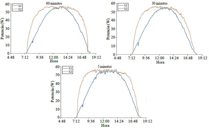
Figure 5 Comparison of power generated by the fixed panel (S1) and DSSF (S2), each movement 60, 30 and 5 min.
The maximum short-circuit flow measured by the sensors was 2.89 A, which is superior to 0.16 A indicated on the rating plate solar panel manufacturer, this may be because the weather conditions during the evaluation were different to the standard test conditions (STC Standard Test Conditions), which are 1 000 W m-2 and 25 °C of radiation temperature in the cell (SEI, 2007). This difference does not greatly affect the results.
The Table 3 shows that, the total daily energy consumption is quite similar in all the three tests, which means that even though the intervals are different DSSF movement, it will consume about the same amount of energy. The total daily consumption to just vary throughout the year depending on solar declination and right ascension. It is also noted that, the DSSF obtained a higher final energy gain if it moves every 60 min, followed by that orients every 30 and 5 min, with values of27.98, 26.81 and 26.27%, respectively, relative to the fixed panel.

The decrease in energy captured by reducing the operating range of the system can be caused by various factors: the increase in cell temperature due to an increase in solar radiation incident thereon and thus a decrease in the output voltage to an increase in ambient temperature, issues related to the flow limits of the flow-voltage solar panel operation, or other factors such as shadows, relative humidity, particles suspended in the atmosphere, wind speed, etc. (SEI, 2007).
Abu-Khader et al. (2008) reported an overall increase of about 30-45% in power output for solar tracking system in north-south axis (NS), when compared to a fixed PV system; while Huang et al. (2011) found that on a sunny day, a tracker of an axis can get 35.6% more energy relative to a fixed PV system; and Kacira et al. (2004) found that, the average daily gain is 29.3% in solar radiation and 34.6% in power generation for a particular July day in Sanliurfa Turkey of a solar tracker with two axes relative to a fixed PV panel. These results are higher than the results obtained in this research, which may be due to the location and time of year, the devices used for measuring the flows and voltages, as well as the different methods of calculation, since calculations in this study took into account a correction for temperature (SEI, 2007).
For testing movement every 60 min, the solar tracker spends 1.36% of the final energy gain for operation, which means that almost all of the energy produced since the implementation of the solar tracking system. It is useful for other applications as well.
The Figure 6 shows that, the DSSF operating hours increases with higher performance to nominal (45 W) for 5 hr in the case of the fixed panel and up to 8 h in the case of panel with tracker, these values may change throughout the year.
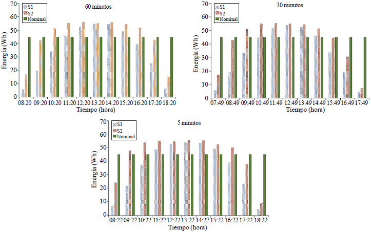
Figure 6 Time energy generated by the fixed panel (S1) and DSSF (S2) compared to the rated capacity of the panels according to manufacturer's specifications, each movement 60, 30 and 5 min.
As shown in Table 4, it was determined that the performance of the fixed solar panel with respect to the global solar radiation (ISR) (1 000 W m-2) (SEI, 2007) is less than the performance reported in the manufacturer's specifications solar panel used (12%) (DASOL, 2012). While the panel tracker obtained 13.27% on the motion test every 60 min, indicating that the solar tracking system increases the performance of the panel in 1.27% of the value of the nominal performance of the panels relative to the ISR, and 2.93% over the performance of the fixed panel.

Conclusions
The software that was developed, turn out to be quite functional for the entire territory of Mexico and throughout the year, since the output data, in both height and sun azimuth are less than 1 degree in most cases with respect to the data provided by the software http://www.sunearthtools.com/software; that allowed the design of the DSSF.
The DSSF allowed to follow the movement of the sun automatically in the horizontal and vertical axis, which is coupled to a photovoltaic panel to improve its efficiency in capturing solar energy.
The best energy performance is obtained when the solar tracker is oriented to the sun every 60 minutes. Regarding the energy generated by a fixed panel, the solar tracker is directed every 60 min produced up to 27.98% more energy, with an energy expenditure of 0.3% of the total energy generated or what is equal to 1.3% of final energy gain. When comparing energy production system with the ISR, it reaches up to 13.27% advantage of the energy available, or in other terms, a 2.93% increase over the fixed panel.
Literatura citada
Abdallah, S. and Nijmeh, S. 2004. Two axes sun tracking system with PLC control. Energy Conversion and Management. 45:1931-1939. [ Links ]
Abouzeid, M. 2001. Use of a reluctance stepper motor for solar tracking based on a programmable logic array (PLA) controller. Renewable Energy. 23:551-560. [ Links ]
Abu-Khader, M. M.; Badran, O. O. and Abdallah, S. 2008. Evaluating multi-axes sun-tracking system at different modes ofoperation in Jordan. Renewable and sustainable energy reviews. 12: 864-873. [ Links ]
Castellanos, A y Escobedo, M. 1980. La energía solar en México; situación actual y perspectivas. 1a Edición. Centro de Ecodesarrollo. D.F., México. 101 p. [ Links ]
Chefurka, P. 2007. Energía y población mundiales, tendencias hasta el 2100. World energy and population. http://www.paulchefurka.ca/WEAP/WEAP.html. [ Links ]
DASOL. 2012. DS-A1-45 Solar panel datashet. DASOL, Zhejiang, China. 1 p. [ Links ]
Gonzáles, M. 2006. Diseño de un sistema de seguimiento solar de un eje para el aprovechamiento de la energía solar en sistemas fotovoltaicos. Ciencia y Desarrollo. México, D. F. 10:43-46. [ Links ]
Huang, B. J.; Ding, W. L. and Huang, Y. C. 2011. Long-term field test of solar PV power generation using one-axis3-position sun tracker. Solar energy. Columbus, Ohio, USA. 85:1935-1944. [ Links ]
INEGI (Instituto Nacional de Estadística, Geografía e Informática). 2010. Principales resultados de censo de población y vivienda 2010. México, D. F. 122 p. [ Links ]
Kacira, M.; Simsek, M.; Babur, Y. and Demirkol, S. 2004. Determining optimum tilt angles and orientations of photovoltaic panels in Sanliurfa, Turkey. Renewable Energy. 29:1265-1275. [ Links ]
Kalogirou, S.A. 1996. Design and construction of a one-axis sun-tracking system. Solar Energy Columbus, Ohio, USA. 57(6):465-469. [ Links ]
Kroposki, B. and DeBlasio, R. 2000.Technologies for the new millennium: photovoltaics as a distributed resource. IEEE power engineering society summer meeting. 1798-801. [ Links ]
Koyuncu, B. and Balasubramanian, K. 1991. Amicroprocessor controlled automatic sun tracker. IEEE Transactionson Consumer Electronics. 37(4): 913-917. [ Links ]
López, A. G. 1985. Sistemas de seguimiento del sol. Mompin, P. J. (Ed.). Energía solar fotovoltaica. Segunda (Ed.). Barcelona, Marcombo Boixareu Editores. 96-101 pp. [ Links ]
Lynch, W.A. and Salameh, Z. M. 1990. Simple electro-optically controlled dual axis sun tracker. Solar Energy. Columbus, Ohio, USA. 45(2):65-69. [ Links ]
Madrid, V. A. 2009. Curso energía solar. Ediciones Mundi-Prensa. Madrid, España. 311 p. [ Links ]
Mosher, D. M.; Bose, R. E. and Soukup, R. J. 1977. The advantages of sun tracking for planar silicon solar cells. Solar Energy. Columbus, Ohio, USA. 19:91-97. [ Links ]
Naaijer, G. J. 1985. Instalaciones solares fotovoltaicas para bombeo de agua. Mompin, P. J. (Comp.). Energía solar fotovoltaica. Marcombo Boixareu Editores. Barcelona, España. 196-212 pp. [ Links ]
Park, K.; Lee, J. H.; Kim, S. H. and Kwak, Y. K. 1996. Direct tracking control using time-optimal trajectories. Control Engineering Practice. Oxford, UK. 4(9): 1231-1240. [ Links ]
Solar Energy International (SEI). 2007. Fotovoltaica manual de diseño e instalación. Pérez, B. H. (Trad.). New Society Publishers. Gabriola Island, Canada. 325 p. [ Links ]
Walraven, R. 1978. Calculating the position of the sun. Solar Energy. Columbus, Ohio, USA. 20: 393-397. [ Links ]
Yousef, H. A. 1999. Design and implementation of a fuzzy logic computer controlled sun tracking system. Proceedings of the IEEE International Symposium on Industrial Electronics. 3: 1030-1034. [ Links ]
Received: May 2015; Accepted: September 2015
 Este es un artículo publicado en acceso abierto bajo una licencia Creative Commons
