


 texto en
  Artículo en XML
 Referencias del artículo
 Enviar artículo por email
 Citado por SciELO
  Similares en
SciELO
Similares en
SciELO 
 Permalink
Introduction
Destructive human activities in recent years have resulted in severe climatic change as well as heavy rains over dam reservoirs (Beniston et al., 2007). Severely heavy rains would rapidly increase water volume in the dam reservoir, eventually leading to the hydrodemolition of the dam. According to the research conducted by The United States Army Corps of Engineers (USACE), 36 percent of the existing dams are unsafe, with 80 percent of them being unsafe due to the low culvert capacity of their weirs (Suprapto, 2013). Due to the catastrophic risks this problem poses to human life, engineers have paid particular attention to increasing the culvert capacity of weirs, which is achieved in most cases by enlarging the dimensions of the weir (ASDSO, 2012). However, this solution is not always effective due to such limitations as insufficient dam space and high costs. For this reason, researchers have been trying to increase the efficiency of dam weirs by modifying their structure (Tiwaria & Sharmam, 2015). The piano key weir (PKW) is one such solution (Figure 1). At a width equal to that of a linear weir, the PKW can produce a larger length and discharge coefficient product (CdL) at a lower Cd (Equation (1)), thus raising its hydraulic efficiency by 3-4 times as compared to the linear weir (Tiwaria & Sharmam, 2015):

In Equation (1), Q is the flow rate; Cd is the discharge coefficient; L is the developed crest length, and H t is the total weir head (sum of the velocity head and the static head) (Tullis, Young, & Chandler, 2007). Due to this advantage, the PKW has received widespread attention among researchers in recent years, prompting them to conduct much research on this type of weir (Ribeiro, Pfister, & Schleiss, 2013) (Table 1).
Table 1 Lists the characteristics of the PKW.
| BT | Total length |
| B | Base length |
| Bo | Upstream(outlet key) overhang crest length |
| Bi | Downstream(inlet key) overhang crest length |
| P | Height of the inlet entrance measured from the PKW crest |
| Wi | Inlet key width (sidewall to sidewall) |
| Wo | Outlet key width (sidewall to sidewall) |
In a PKW, energy dissipation is caused by the increase of water head at the upstream section of the dam as well as the formation of vortex regions due to the flow impacting the weir walls (in the lower parts in particular) (Kabiri-Samani & Javaheri, 2012).
The PKW was first proposed by Lempérière and Ouamane (2003). In their study, they showed that there were two dominant flows in the PKW which is classified as a multi-purpose curved weir. In the first model, the inlet key attracts the nearby flows and subsequently discharges them (via precipitation) over the inlet crest to the downstream section (similar to a sharp-crested weir with a sloped body) (Lempérière, 2017). In the second model, the flow is discharged into the downstream section of the key slope upon passing over the outlet crest (Lempérière, 2017). However, due to the jet damaging the downstream structure, measures including increasing wall thickness and building still basins at the downstream section are necessary to maintain the stability of this structure. In spite of their high initial costs, stepped weirs can reduce energy dissipation in the weir, thus reducing the overall construction costs (Chanson, 2001). The energy dissipation effect of the steps would reduce the depth, the length, and the lateral wall thickness of the downstream still basin, thus leading to substantially reduced construction costs (Chanson, 2001). In their study, Dermawan and Legono (2011) examined the residual energy and the relative energy dissipation in a model stepped weir (slope = 45°; height = 100 cm; width = 30 cm). In their test which comprised five steps, they placed 2, 4, 8, 16, and 32 steps between the weir crest and its toe, and measured five different flows (between 1.73 and 6.15 l/s) for each test step. Their obtained results showed that, no matter how many test steps were conducted, energy dissipation decreased with increasing the yc/H ratio.
In this study, the energy dissipation in a PKW was initially measured. Then, by mounting steps and baffles onto the weir, the respective energy dissipation in each case was determined.
Materials and methods
The experiments were conducted in a metallic flume (length = 7 m; width = 60 cm) with glass walls at the Water and Electricity Organization Laboratory, Khuzestan, Iran. A point depth meter (measuring accuracy = 1 mm) was used to measure water height at the upstream and downstream of the weir. The flow rate was measured via a manometer and a calibrated triangular weir (Figure 2, a).
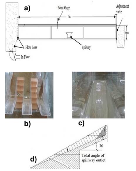
Figure 2 (a) Schematic of the laboratory flume; (b) stepped PKW; (c) baffled PKW, and (d) schematic of weir angle.
Three Plexiglas models with slope angles of 30, 35, and 40 were developed for simulating the PKW (Figure 2, b, c, d).
In this study, Wi is the inlet key width (= 10 cm); W0 is the outlet key (= 10 cm); Wu is the width of one cycle; W is the flume width; B is the weir length (from upstream to downstream) (= 40 cm); Bi is the length of the downstream slope; Hr is the tailwater (downstream) depth of the weir; Hs is water height over the crest of the weir; P is the weir height (= 20 cm); L is the weir crest length (= 40 cm), and L0 is the length of the outlet key
Separate parts were used to simulate the steps and baffles (Hb represents the step/baffle height). Upon installing the weir and sealing it with aquarium glue, a butterfly valve was used to control the water flow rate into the flume. Water depths at the weir upstream (in the laminar region 40 cm from the weir, for higher accuracy) and at the downstream of the key outlet were measured via the depth meter. Equation (2) and Equation (3) were used to calculate the energy dissipation in the weir:
Using the upstream water depth (y 0), the downstream water depth (y 1), and the flow velocity (calculated from Equation (4)), the energy at each section was calculated. The relative energy dissipation for the flow was then obtained from the following equation:
Dimensional analysis
The parameters affecting the energy drop are shown in Equation (5):
where
In Equation (6), S
is the ratio of
Since the lowest Reynolds number in this paper is 3 500, the effect of Reynolds number is neglected. Moreover, given the fixed weir geometry, the final relation for the dimensionless parameters affecting the coefficient of discharge is expressed by Equation (7):
It should be noted that the Froude number at the upstream of weir for all the models were below 1, meeting the conditions subcritical flow at the upstream.
Results and discution
To study the effect of the steps and baffles on the energy dissipation in the weir,
different experiments were designed where models with different step heights (1, 2,
and 3 centimeters); three cubic baffles (with side lengths of 1, 2, and 3
centimeters), and three PKWs (with slope angles of 30, 35, and 40 degrees) were
tested. Overall, 180 experiments were conducted at flow rates ranging from 1 to 50
l/s. The relative energy dissipation
The respective effects of the dimensionless yc/H ratio (which expresses the effect of flow rate as well as weir water head) and the Weber number (which indicates the effect of surface tension due to direct contact between the flow and the weir structure) on the energy dissipation were duly examined. Table 2 shows the summary of the results.
Table 2 The summary of the results.
| Model | The angle | Max relative energy loss | yc/H |
|---|---|---|---|
| Observational | 30 | 8.2125 | 1.69 |
| Bafel 3 cm | 30 | 8.5565 | 1.93 |
| Bafel 2 cm | 30 | 8.5565 | 1.93 |
| Bafel 1 cm | 30 | 8.2125 | 1.69 |
| Observational | 35 | 8.6487 | 1.5 |
| Bafel 3 cm | 35 | 8.1682 | 1.93 |
| Bafel 2 cm | 35 | 1.9412 | 1.13 |
| Bafel 1 cm | 35 | 6.1749 | 1.69 |
| Observational | 40 | 2.9417 | 1.04 |
| Bafel 3 cm | 40 | 1.9551 | 1.04 |
| Bafel 2 cm | 40 | 1.9551 | 1.04 |
| Bafel 1 cm | 40 | 1.6857 | 1.04 |
| Observational | 30 | 8.2125 | 1.69 |
| Stairs 3 cm | 30 | 7.2535 | 1.69 |
| Stairs 2 cm | 30 | 7.7988 | 1.5 |
| Stairs 1 cm | 30 | 6.8365 | 1.52 |
| Observational | 35 | 8.6487 | 1.5 |
| Stairs 3 cm | 35 | 6.2094 | 1.5 |
| Stairs 2 cm | 35 | 7.0511 | 1.59 |
| Stairs 1 cm | 35 | 6.3829 | 1.57 |
| Observational | 40 | 2.9417 | 1.04 |
| Stairs 3 cm | 40 | 3.5269 | 1.39 |
| Stairs 2 cm | 40 | 3.407 | 4.71 |
| Stairs 1 cm | 40 | 3.8271 | 1.34 |
Effect of yc/H on relative energy loss
The effect of yc/H on the relative energy dissipation was studied in two parts. In the first part (depicted in Figure 3), the effect of step/baffle height on energy loss; and in the second part (shown in Figure 4), the effect of slope angle on energy dissipation was studied.
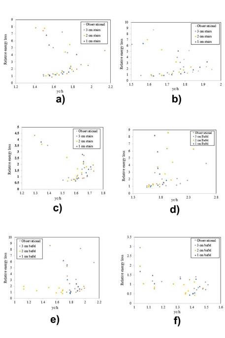
Figure 3 Stepped weir with (a) 30° slope angle; (b) 35° slope angle; (c) 40° slope angle and baffled weir with (d) slope angle of 30; (e) slope angle of 35°; (f) slope angle of 40°.
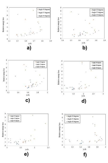
Figure 4 (a) A large step (height = 3 cm); (b) a medium step (height = 2 cm); (c) a small step (height = 1 cm); (d) a large baffle (height = 3 cm); (e) a medium baffle (height = 2 cm); (f) a small baffle (height = 1 cm).
As can be observed in Figure 3 (a, b, c) (where energy losses corresponding to three different slope angles were calculated), increasing yc/H from 1.5 to 1.7 increased the relative energy loss. However, this trend was reversed as yc/H was increased from 1.3 to 1.4, which led to a corresponding decrease in the energy loss. According to these diagrams, increasing the step height increased energy loss. However, the greatest energy dissipation in the unstepped weir occurred at yc/H > 1.3. Since yc/H exhibits the effect of flow rate, and this increase in energy dissipation occurred at smaller yc/H values, we can conclude that, at lower flow rates (i.e., lower flow velocities), a smaller flow separation area was formed in the unstepped weir, thus causing greater energy loss.
As can be observed in Figure 3 (d, e, f), increasing dimensions of the cubic baffles decreased energy dissipation at all the three slope angles. This result was enhanced as the flow rate increased since, at lower flow rates, the energy dissipation difference among the three models was very small. The greatest energy dissipation was obtained for the weir with a 30° slope angle fitted with a small baffle. This result confirms the fact that reducing the outlet key space would increase the flow rate as well as the energy in a PKW. Hence, smaller baffles must be used for obtaining greater energy loss.
Figure 4 (a, b, c) shows the effect of the slope angle on the energy dissipation in the tested stepped weirs. It was concluded from these diagrams that the greatest energy dissipation corresponding to the 1.6 < yc / H < 2.0 interval was obtained in weirs with greater step heights. However, the maximum dissipation in the lower yc/H values occurred at a step height of 1 cm; indicating that, at higher velocities, the energy dissipation increased in weirs with a step height of 3 cm due to the formation of a smaller separation zone in such weirs.
Figure 4 (d, e, f) shows the effect of weir slope angle on energy dissipation in weirs with cubic baffles. As can be observed, energy dissipation is inversely related to slope angle, so that increasing the former would lead to a decrease in the latter. Therefore, the effect of baffles on energy dissipation reduction diminished as baffle height was increased.
Effect of Weber number on relative energy dissipation
The Weber number was calculated from Equation (9):
Figure 5 and Figure 6 show the results obtained in the section. As in the previous section, these results entail two parts.
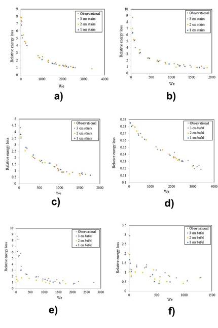
Figure 5 Stepped weir with (a) a slope angle of 30°; (b) a slope angle of 35°; (c) a slope angle of 40°; (d) a 30° baffle; (e) a 35° baffle; (f) a 40° baffle.
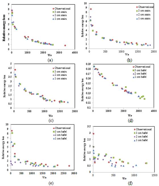
Figure 6 (a) A large-sized step (height = 3 cm); (b) a medium-sized step (height = 2 cm); (c) a small-sized step (height = 1 cm); (d) a large-sized baffle (height = 3 cm); (e) a medium-sized baffle (height = 2 cm); (f) a small-sized baffle (height = 1 cm).
As can be observed in Figure 5 (a, b, c), increasing the Weber number reduced the energy loss. In the 1 < We < 500 range, a 45% energy dissipation was obtained for the unstepped weir. Increasing the Weber number changed this trend however, leading to greater energy dissipation in the stepped weirs. A maximum energy dissipation of 5% was obtained at We = 500 in the weir with a step height of 3 cm. As can be clearly observed in these figures, the greatest relative energy losses occurred at We > 1 500 for the following weirs respectively: the weir with no steps, the weir with small-sized steps, the weir with medium-sized steps, and the weir with large-sized steps. As can be observed in Figure 5 (d, e, f), increasing the Weber number led to a decrease in energy loss. Conversely, the greatest energy losses were obtained for the weirs with large baffles, medium baffles, small baffles, and the weirs without bafles, respectively.
As can be observed in Figure 6 (a, b, c), as the Weber number increased, the greatest energy losses of circa 69, 65, and 39 percent were obtained for the weirs with steps heights of 1, 2, and 3 centimeters, respectively.
As can be observed in Figure 6 (d, e, f), similarly to the stepped weirs, the energy dissipation in the baffled weirs as well as the effects of the installed steps and baffles decreased with the slope angle. However, unlike the case of stepped weirs where increasing the step height reduced the relative energy dissipation, increasing the height of the cubic baffles led to a corresponding reduction in energy dissipation
Effect of specific discharge coefficient
In this section, the effect of step height on the specific discharge coefficient (which is an index of weir efficiency) is examined (Figure 7).
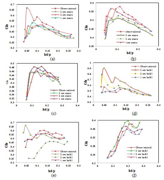
Figure 7 Variations of Cds with hd/p at (a) slope angle of 30°; (b) slope angle of 35°; (c) slope angle of 40°; (d) slope angle of 30°; (e) slope angle of 35°; (f) slope angle of 40°.
As can be observed in the Figure 7, the maximum discharge coefficient was obtained for the unstopped weir which yielded the highest efficiency; and increasing the step height reduced the specific discharge coefficient. It can be concluded from Figure 7 that a larger baffle would increase weir efficiency beyond the observed value. This exhibits the fact that though a large baffle exhibits a negative effect in terms of energy loss, it brings about a positive effect in terms of efficiency by increasing the weir efficiency.
As can be observed in Figure 8, the maximum discharge coefficient (0.65) was obtained for the unstepped weir which also exhibited the highest efficiency. Increasing step height also led to a corresponding decrease in the specific discharge coefficient. A maximum discharge coefficient of 0.55 was obtained for the 35° weir with a step height of 1 cm, whereas a minimum discharge coefficient of 0.34 was obtained in all the three weir models for a step height of 3 cm.
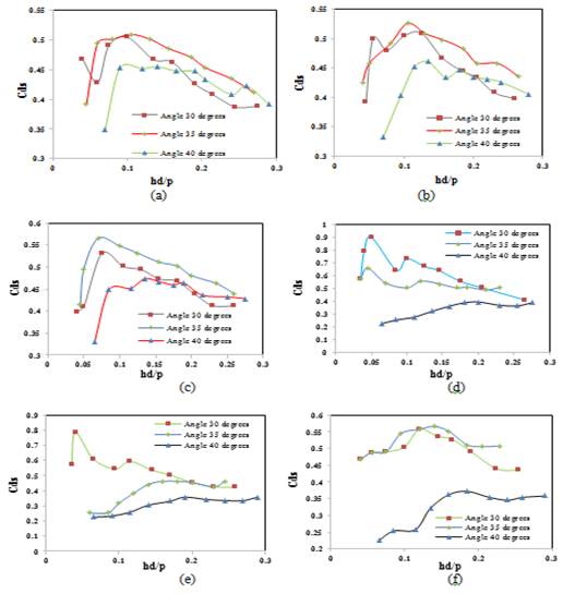
Figure 8 Variations of Cds with hd/p at (a) step height of 3 cm; (b) step height of 2 cm; (c) step height of 1 cm; (d) a 3 cm bafle; (e) for a 2 cm bafle; (f) a 1 cm baffle.
It can be concluded from Figure 7 and Figure 8 that increasing the slope angle led to a corresponding increase in weir efficiency. However, increasing the baffle dimensions decreased the efficiency: for the 3 cm baffle, a maximum efficiency of 0.85 was obtained at an angle of 30°. For the 2 cm (medium) baffle, a maximum energy dissipation of 0.8 was measured at an angle of 30°. Ultimately, a maximum efficiency of 0.55 was obtained for the 1 cm baffle at the same angle of 30°.
Conclusions
The results obtained in the present study showed that baffled and stepped weirs produced energy losses of 85 and 80%, respectively. Therefore, baffles have a greater effect on the energy dissipation across the weir. In addition, the slope angle of the outlet keys was found to be inversely related to the weir energy loss. However, the most significant point was that the effect of weir steps on energy dissipation decreased with increasing flow rate.
At Weber numbers lower than 1 500, the greatest energy losses were obtained for the weir with no steps, the weir with small steps, the weir with medium steps, and the weir with large steps respectively. As for the baffled weirs, the greatest losses were achieved for the weir with large baffles, the weir with medium baffles, the weir with small baffles, and the weir with no baffles respectively.
Increasing the height of steps led to a corresponding increase in the energy dissipation in the stepped weirs. In the baffled weirs, however, the reverse occurred, i.e., the energy dissipation increased by reducing the baffle height.
The greatest discharge coefficient (0.65) was obtained for the unstepped weir which exhibited the highest efficiency. Increasing the step height reduced the specific discharge coefficient. A larger efficiency (than the observed efficiency) was obtained by installing a large baffle on the weir; however, decreasing the baffle dimension led to a corresponding energy drop resulting in a reduction in efficiency below the observed efficiency.

