Introduction
A dynamic seal is basically composed of a plastic or elastomeric ring (sealing lip) bonded to a steel frame in order to achieve an interference fit with the shaft while a preload is produced. Their function is based on the formation of an elasto-hydrodynamic oil film between the lip and the shaft while leakage is prevented by an auto-pumping action from the air-side toward the liquid-side of the seal to promote sealing and extended life [1]. The lips are mainly made of polymers and elastomers, such as: PTFE, nitrile, polyacrilate, flouroelastomer, silicone, neoprene, etc. [2]. In general, they exhibit advantages, such as: high elasticity, moderate creep and stress relaxation, relatively good resistance to abrasion, impermeability, and chemical resistant to different media [3], which are very important parameters to reach good sealing performance.
Dynamic seals are prone to fail because of different situations, however, wear is one common failure cause. The wear generated on the sealing lip is basically generated by the prolonged contact sliding condition. However, the normal lubricated wear can be significantly accelerated either by lubricant starvation and/or working under the action of lubricant contaminated with hard debris [2]. Lubricant starvation may cause two-body abrasion, which is directly produced by the effect of the shaft roughness against the sealing lip. On the other hand, the contamination of lubricant with hard debris may generates three-body abrasion, which occurs by the interaction of the free hard particles (debris) at the sealing interface. In general, abrasion of elastomers has been studied by Zhang [4]. He tested rubber samples under two different conditions (dry and wet contact) by using a pin on disc tester. The wear found was categorized into dry abrasion and wet abrasion. Dry abrasion was produced by the sliding of a hard surface against the elastomer surface in dry contact. The wear pattern appears as a series of periodic parallel ridges perpendicular to the sliding direction, which is well known as "tearing". Tearing is fundamentally the abrasion wear mechanism of rubber. It is a roll formation initiated by cracks. They are produced by an initial building-up of stress. The cracks are nucleated at the front of the abrader (asperities), so the tangential stress decreases drastically [5]. In macro-scale, the worn surface presented a corrugated texture made of micro and macrodelaminations, which is occasioned by micromolecular fracture or repeated rupture of molecular chains under the action of repeated mechanical stress produced by the asperities sliding [4]. On the other hand, wet abrasion was classified into wet abrasion acted by free particles (hard debris), as well as abrasion produced by fixed particles in a lubricated media. The wear mechanisms corresponded to a local irregular micro-tearing process with micro-layered surface made of micro-tearing traces [4-6]. Similarly, this wear pattern was also found in previous research of micro-abrasion in silicone and nitrile rubber materials [7,8]. There are some standard methods to determine the two-body abrasion resistance of rubbers, such as: ASTM D4060, ASTM D2228 and ASTM D5963. They comprise the characterization of wear resistance under extreme dry conditions. However, the approaching of a realistic working situation of dynamic seals is required to study rubbers in this particular application, so various experimental test methods have been developed. The tests include an approximation of two-body abrasion under dry and wet/lubricated conditions, and three-body abrasion using a mixture of lubricant with hard debris [1,4,9-11]. Nonetheless, these tests involve extremely long runs due to the lubricated contacts and low accuracy since the scars are considerably inconsistent. Hence, an accurate and accelerated test method is needed to evaluate wear of sealing elastomers by saving time consuming and reducing testing costs.
The aim of this work was to study the particular wear patterns and the wear progression under the action of two-body and three-body abrasion of an elastomeric material extracted from an actual dynamic seal by using a micro-scale abrasion tester. The tests were run under dry and muddy conditions in order to reproduce both wear types.
Experimental details
Test apparatus
A TE66 micro-scale abrasion tester was used in order to carry out the wear experiments. The test apparatus schematic is depicted in Figure 1. Fundamentally, it is utilized to reproduce micro-abrasion (three-body abrasive wear) on hard materials, however, it was used to conduct two-body and three-body abrasion tests in this investigation. The test consisted on producing wear on small elastomeric samples by contacting a rotary ball in dry and muddy environments. Basically, the specimen is set vertically on a pivoted L-shaped arm. It is loaded against the rotary ball with a designated normal force. The load is applied to the arm via dead weight, which is situated on the horizontal lever. In order to balance the arm, the counterweight is previously adjusted. The ball is secured between two coaxial driving shafts and rotated by a motor at a selected and constant speed. The sliding distance and speed are controlled during the whole test. In order to reproduce the muddy environment, a slurry is dripped by a syringe onto the ball to be entrained into the contact by the rotary effect.
Sample preparation and characterization
The specimens were extracted from an actual commercial dynamic seal. It consisted of a nitrile butadiene rubber (NBR) lip without steel frame. The lip was completely flat. Hence, the samples were cut from the lip towards achieve small flat pieces, as it is shown in Figure 2.
On the other hand, commercial steel balls (AISI 52100) with 25.4 mm in diameter were used as the rotary ball samples. They were superficially conditioned by etching them into 20 % nital solution during 30 s towards reach a fine pitting surface with a uniform roughness 0.35 ± 0.5 μm Ra in order to achieve consistent three-body abrasive wear scars as that suggested in the micro-abrasion (three-body abrasion) method for hard materials [12,13], as well as to reach the average roughness suggested for the surface finishing of actual rotary shafts, and thus approaching the actual seal/shaft interface condition [14]. The mechanical properties of the NBR samples and the rotary balls are seen in Table 1.
Table 1 Mechanical properties of ball and NBR specimens.
| Specimen | E [GPa] | V | Hardness | Roughness [μm] |
|---|---|---|---|---|
| Ball | 200 | 0.3 | 848 HV | 0.3 ± 0.05 Ra |
| NBR | 0.012±0.01 | 0.49 | 63 Shore A | 0.44 ± 0.15 Sa |
The ball roughness was measured by using a contact profilometer (Dektak 150 stylus) while the roughness of the NBR samples was evaluated by an optical profilometer (Contour GT-K, Bruker). An approaching of the elastic properties (Young's modulus) of NBR specimens was obtained by instrumented Berkovitch nano-indentation tests (CSM Instruments, TTX-NHT). They were conducted at room temperature (22 ± 2 °C). The indenter was held at a maximum load of 5 mN and the loading rate was selected as 30 mN/min. A load holding period of 10 s was given. A total of 5 indentations were performed for each sample. The poissons ratio (v) was obtained from values reported for common elastomers [15]. Additionally, in order to determine a representation of the viscoelastic behaviour of the NBR specimens, a compression stress relaxation test was performed. It consisted on setting a sample between two plates and then compressing it to a predefined constant strain (30 ± 5 %). A load cell was connected to the upper plate, which records the force value to a computer. The force was monitored during 240 minutes. Hence, the representation of the stress relaxation behavior of the samples with time at a specified constant deformation is seen in Figure 3.
Test method
The tests were carried out in dry and muddy contact. Firstly, they were conducted under dry condition to produce two-body abrasion. Secondly, an abrasive agent made of distilled water with high concentration of SiC micro-particles (grade C5, F1200, approximately 4 μm particle size with angular morphology) were used to generate consistent three-body abrasive wear scars [7,12,13,16]. The slurry was adequate to generate three-body abrasion as well as to avoid any physical degradation of the elastomeric samples since the NBR can be incompatible with some oils. The test conditions for both experiments are given in Table 2. In actual dynamic sealing interfaces, the maximum contact pressure varies from 1 to 4 MPa depending on the working conditions and the particular design of seals [17]. Hence, the applied load was selected to approach a mean contact pressure close to the actual contact pressure. The contact pressure was estimated by Hertz theory for a ball on flat contact [18]. The estimated value only corresponded to the instantaneous contact pressure since the stress under compression is relaxed with time, as shown in Figure 3. The experiments were run at room temperature (22 ± 1 °C). Particularly, in order to perform the trials in muddy environment, 0.5 ml of abrasive agent was applied to the contact for each 10 cycles. The ball cycles were varied from 0 to 500 with intervals of 100 to determine the wear progression. The ball was rotated for each 50 cycles in order to have a pitting surface track during the entire test and the ball was substituted each 500 cycles for a new ball.
Table 2 Experimental test conditions.
| Condition | Experiment | |
|---|---|---|
| Two-body abrasion | Three-body abrasion | |
| Environment | Dry | Muddy |
| Load [N] | 1.5 | 1.5 |
| Sliding speed [m/s] | 0.11 ± 0.01 | 0.11 ± 0.01 |
| Cycles | 0 - 500 | 0 - 500 |
| Sliding distance [m] | 0 - 39.9 | 0 - 39.9 |
According to the stress relaxation behavior of the samples, it was observed that the stress relaxation was majorly stabilized after the first hour under compression. Thus, a stress relaxation time (1 hour) was given before conducting the wear test in order to reduce the variation in contact pressure. The relaxation period started once the ball contacted the NBR sample. After that period, the ball sliding initiated. In preliminary testing, it was observed that the repeatability of results was improved by giving this relaxation time. A new NBR sample was used for each trial. Besides, three similar tests were performed for each experiment to see repeatability.
Results and discussion
Morphology of wear craters
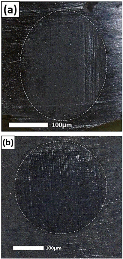
The wear patterns of the scars were analyzed by using an optical microscope, Scanning Electron Microscope (SEM) (JEOL JSM-7800F) and an optical profilometer (Contour GT-K, Bruker) in order to see the morphological and topographical characteristics. In Figure 4, images from the scars taken by the optical microscope are shown. According to the contact configuration (ball on flat contact), it was expected to achieve scars with circular geometry as that seen in Figure 4b. However, some specimens tested under the action of two-body abrasion exhibited scars with irregular shape as that illustrated in Figure 4a. The shape irregularities were perhaps occurred since the friction hysteresis is enlarged in a dry rubber contact because more adhesive conjunctions are easily formed [6], so the friction force generates a deformation/distortion in the sample, which is caused by the shear strength generated by the ball sliding through the test. On the other hand, in the three-body abrasion testing, the slurry acts as lubricant in the interface, which reduces friction considerably. Hence, wear craters more consistent with circular geometry were achieved. It is noteworthy that the shape irregularities perhaps were also produced due to a misalignment between the L-shape arm and the rotating ball occurred by the sample size and its thickness.

Figure 4 (a) Image from a wear scar produced by two-body abrasion; (b) Image from a wear scar produced by three-body abrasion.
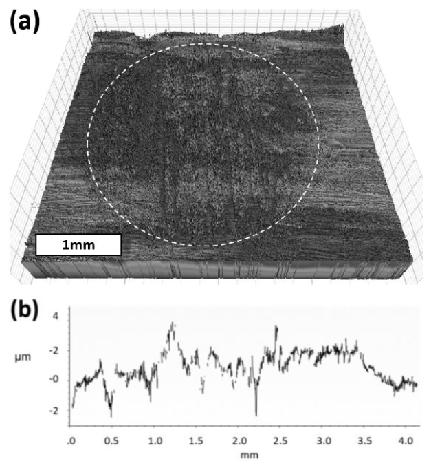
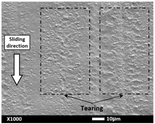
In Figures 5 and 6, images from a typical scar produced by the action of two-body abrasion are illustrated. The topography of the wear crater is visualized in Figure 5. It can be seen that the roughness was increased perhaps because of the formation of tears on the whole wear crater. The tears looks like protuberances on the surface of the bulk material, as that reported by Zhang [5] and Liang et al.[6] for wear of elastomers in dry contacts. In Figure 6, the wear pattern can be more clearly identified. It consisted of several tears without defined arrangement (tearing). The irregular tears were perhaps produced by the repeated pass of the sphere's asperities during the sliding motion, similar as that reported in earlier research works [5-7]. In addition, Mofidi and Prakash [19] found a combination of two wear mechanisms in elastomers produced by the action of two-body abrasion in dry contacts in reciprocating motion. The former is supposed to be occurred by the sliding of an elastomer against sharp asperities in point contacts, so the elastomer surface is pulled in the sliding direction failing in tension behind the contact perpendicular to the tensile stress field while the second one is produced by the sliding of the elastomer in line contact with an abrader, so the tears are generated perpendicular to the direction of sliding at the rear of the contact region, producing tearing. Thus, the protuberances (tears) found in the scars can be also related to this wear mechanism.

Figure 5 (a) 3D-Image from a wear scar produced under the action of two-body abrasion; (b) horizontal profile from the scar.
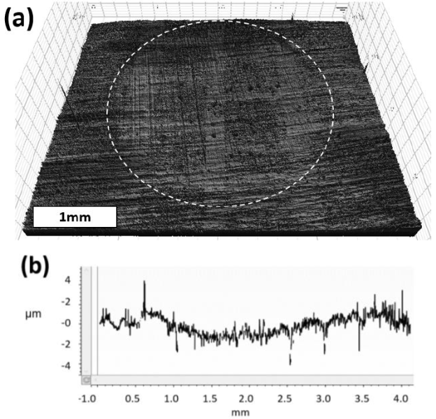
On the other hand, Figures 7 and 8 exhibit the characteristics of a typical wear crater generated by the three-body abrasion test. The scar showed a different wear pattern than that seen in the scars generated by two-body abrasion. Hence, it was identified a micro-stripped texture with regular arrangement, as it is seen in Figure 8 in detail. The texture was mainly composed of micro-traces parallel to the ball sliding direction. Thus, such traces were produced by the action of the SiC particles movement into the interface. Besides, indentations of SiC and some cavities were localized on the entire wear crater, so the wear pattern could be principally influenced by the rotation, dragging and indentation of the abrasive particles along the contact area on the elastomeric surface, similar to that reported for silicone rubber [7].

Figure 7 (a) 3D-Image from a wear scar produced under the action of three-body abrasion; (b) horizontal profile from the scar.
Wear progression
The wear volumes were measured by the optical profilometer software. A comparative of the lost volumes against ball cycles for two-body and three-body abrasion is seen in Figure 9. Overall, the three-body abrasion was more severe than two-body abrasion on the NBR. It perhaps was produced because the stress was considerably intensified by the action of SiC particles into the interface, so the elastomeric surface was more vulnerable to be damaged.
The standard deviation obtained in dry abrasion experiments was larger than that obtained by conducting three-body abrasion tests. It perhaps was produced since some scars obtained by two-body abrasion test had irregular geometry, as it is seen in the scar showed in Figure 4a.
Finally, both abrasion types were positively reproduced by these tests, exhibiting the particular abrasive wear patterns. In comparison with other tests reported in literature for sealing elastomers [1,4,9-11] and the standard methods: ASTM D4060, ASTM D2228 and ASTM D5963, this test is very suitable since the advantages exhibited, such as: use of small test pieces, generation of localized wear craters with particular wear characteristics, the testing cost and the time-consuming are very low, and the test conditions can be adequately controlled and monitored.
On the other hand, in this work, samples extracted from an actual seal were tested, however it produced some limitations for testing and material characterization. In order to conduct further work, it is suggested testing larger specimens extracted from prepared flat sheets of elastomer with particular characteristics of interest.
Conclusions
Two-body and three-body abrasion on NBR samples were separately generated by using the micro-abrasion tester. The particular wear pattern regarding each abrasion type was successfully achieved.
The pattern of two body abrasion on NBR found consisted on several tears without defined arrangement (tearing) along the sliding direction while the pattern of three-body abrasion was identified as a micro-stripped texture with regular arrangement parallel to the ball sliding direction. The texture was mainly composed of several micro-traces produced by the action of the SiC particles movement into the interface.
It was found that the NBR specimens were more damaged by the action of three-body abrasion.
The test exhibited some advantages to be employed as an accelerated wear test to characterize dynamic sealing materials according to their two-body and three-body abrasion resistance.


 nueva página del texto (beta)


