


 nova página do texto(beta)
 Inglês (pdf)
 Artigo em XML
 Referências do artigo
 Enviar este artigo por email
 Citado por SciELO
  Similares em
SciELO
Similares em
SciELO 
 Permalink
1. Introduction
The energy conversion process in a typical crystalline solar cell occurs due to the absorption of photons that excites the valence and conduction bands of the semiconductor material, generating charge carriers to create electron-hole pairs, therefore a photocurrent is generated and collected by metallic contacts allocated in the top surface of the solar cell. A common geometric arrangement of the metallic contacts in rectangular solar cells is the H-pattern with finger-like contacts. The width of these contacts generates a small series resistance, for a wider electrode, the coverage of the solar cell is restricted, limiting the light transmission through to the semiconductor material junction (Reinders et al. 2017). One of the major focus needed to understand the mechanism that increases the performance of solar cells is the reduction of the resistive power losses of the arrangement for the front metallic contacts. Moreover, different loss mechanisms are associated to the grid metallic contacts as grid resistance, shadowing due to grid reflection, emission of layer resistance and contact resistance between the metal contact and the semiconductor junction (Wen et al., 2010). The process of collection between optically transparent and conductive materials, is limited since electrical carriers invariably scatter photons.
The H-pattern of metallic contacts in rectangular solar cells, inherently has a series of restrictions for the total collection, electrically inserting a series of contacts in parallel, connected with two busbars at right angles, implies the appearance of small losses that result in the efficiency, that is increased by assembling an array of cells of the collecting network to form a photovoltaic module (Reinders et al., 2017). On the other hand, in a solar cell with circular geometry, generated by cutting thin layers of semiconductor material, the pattern of metallic contacts is composed of circular concentric (fingers) and radial contacts (busbars), where the main weakness was that not takes advantage of the total collection area (Patel, 2005). In both geometries, a key factor is to maximize the electrical conductance and minimize the blockage of light. In this manner, the shape and structure are subjects of design the allocation of metallic material to reduce the shading losses and the associate resistive losses (Aiken & Barnett, 1999). The influence of the metal grid pattern, linear and square, the resistive losses are less sensitive to illumination for the square grid than the linear arrangement, also, the resistive losses of the square grid are less influenced by the metal grid resistivity (Morvillo et al., 2009).
In this manner, the geometric arrangement of the top metallic contact network in a solar cell can be designed for optimal coverage and collection of the photogenerated electrical current, for solar cells with increasing conversion efficiency capacity (Müller et al., 2020). Conventional approaches of simple metallization patterns, such as the H-pattern, a cross-hatched pattern or a full metallization have been studied for square geometries (Burgers, 1999; Wen et al., 2010). The grid design in a solar cell with circular geometry, generally used in concentration applications, considers a radial and concentric arrangement of metallic contacts (Bendib et al., 2012; Bissels et al., 2011). Both approaches consider the loss mechanisms related to the grid as shadowing losses, top layer resistance towards the fingers, contact resistance at the fingers, and metal resistance in fingers and busbars. Recently, a conceptual design based on nature-inspired fractal structures has been proposed in flexible electrodes for solar cells (James & Contractor, 2018), where the engineering design provides an optimal surface coverage and enhances the collection of electrical energy in optoelectronic devices (Han et al., 2014).
On the other hand, constructal law allow us to design, predict and enhance the performance of physical systems, to generate evolutionary architectures in systems with imposed currents that flow through the physical system (Bejan & Lorente, 2008). This methodology has proved to describe and predict vascular networks in functionalized vascular structures as the human liver or in cell matrix growth (Lorente et al., 2020; Sauer et al., 2021), thermal energy storage systems (Malley-Ernewein & Lorente, 2020), where the internal tree-shaped structures improve the transport of currents that flow through the system. The evolution of these structures in human and non-human made systems, depends to the degree of freedom to generate and adapt the flow architectures to persist in time with an improved performance (Lorente & Bejan, 2019). In this sense, the constructal law design provides the methods to predict, design and develops evolutionary structures generating vascularized systems (Wang et al., 2007). These structures are determined by the reduction of the resistance to flow subject to local restrictions to satisfy a main objective (Bejan, 2000) and were developed mainly for reticular structures of high conductivity material inserts for cooling an adiabatic volume with an internal heat source (Bejan, 1997a), flow structures in a porous volume (Bejan, 1997b), defining aspect ratios of the inserts or tubes constructions, width ratios between inserts branches and surface covering in order to efficient the heat transfer or flow rate over a volume. he constructal law design has been considered also in solar cells and energy applications (Morega & Bejan, 2005; Ojeda et al., 2020).
In parallel, a tree-shaped pipe network in a disc-shaped body was designed for the optimal fluid flow between a point and multiple points in the perimeter (Wechsatol et al., 2002) and the geometric characteristics as the length of the branched pipes and angles of bifurcation were defined as a minimization of the flow resistance. The main feature of the optimized networks, which are defined by the constructal law design methodology, is the allometric relationships between characteristic lengths of the physical system as a function of physical and geometrical variables (Miguel, 2015). An application of the tree-shaped networks for cooling a volume was reported by Rocha et al. (2002), where the lengths and angles of ramification allow the compaction of the system. A common feature of the design process is to define and minimize the quantity of conductive material with coverage of the area. A generalized methodology for the optimal branching design of networks for fluid flow and heat transfer was developed by Miguel (2018).
Also, the constructal law design methodology developed for the cooling of a volume with a heat generation source with a reticular pattern of high conductivity inserts (Bejan, 1997a; Ledezma et al., 1997), has been applied for the design of the grid of metallic contacts in circuits and solar cells. The resulting geometric arrangement follows an H-pattern network of contacts with constant cross-section (Morega & Bejan, 2005), a tree-like pattern (Ojeda et al., 2020), and optimal variable cross-section (Chen et al., 2010) in a rectangular solar cell. The main results are the optimal size of the constructal elements, number of branches, and length of the metallic contact. Such a process considers the minimization of the maximum voltage in order to get the minimum electrical resistance in every element of construction. This last characteristic is not necessarily desirable in the design process of a network projected to collect the electric current generated in a solar cell. On the other hand, in the collecting process of the generation of electric current in a solar cell due to solar radiation exposure, various mechanisms of optical and electrical losses are presented. The design of the network from the minimization of the resistive power losses from the overall voltage of the constructal element then defines the optimal length of the contact in every level of branching (Bhakta & Bandyopadhyay, 2005).
As a common assumption in the constructal design process applied to electrical cases, it is convenient to consider that the electrical conductivity σ or resistivity ρ are constants. For this purpose, a vein power tree with optimal cross-sectional branches was designed based on constructal theory, in an elliptical circuit board for optimal distribution of direct current performance (Huang, Guo & Chu, 2011). In this case, the optimal distribution of the electrical resistance is a key factor to determine a structure with minimal resistance. A similar case for a hierarchical concentric contact network is defined in a circular circuit board where the voltage is defined in a circular sector (Huang et al., 2011). The optimal length, number of circular sectors, optimal resistance and voltage, were defined as a function of physical and geometrical parameters.
In this last work, a tree-shaped network for a disc with a heat generation source was defined by the constructal law method for cooling volumes with inserts of high thermal conductivity. The optimal number of sectors and angles of ramification is a consequence of minimizing the thermal resistance for two levels of branching, as was illustrated by Rocha et al. (2002). Also, for the electrical case, a tree-shaped network on a disc-shaped circuit board is defined under the assumption of a fixed area. The metallic contact network connects the center to multiple points to the periphery, increasing the compaction for printed circuit boards for power distribution, geometry factors as the ratio of the widths is considered as a design parameter that defines the optimal length and aspect ratios for the circular sectors (Huang, Guo & Ye, 2011).
In the present work, a theoretical study of the geometric design of the top metallic contact network is developed over a disc-shaped body solar cell, applying the constructal design methodology for the minimization of the resistive power losses. The optimal geometric characteristics of the contact network over the solar cell as the number of sectors, angles of branching, disc size, and lengths, are expressed in terms of the allocation of the metallic material, physical and geometrical parameters, which will be defined later in dimensionless variables.
2. Elemental circular sector
It is well known that the efficiency of a single solar cell is defined by the physical and chemical structure of the solar cell and metallic contact material, which defines the characteristics of the voltage of the equivalent electrical circuit. The electrical potential is assumed as not constant, due to the resistance of the solar cell material of the elemental circular sector, the electrical current flow causes a potential drop to occur, this causes a resistive power loss and consequently a decrease of the efficiency of the solar cell. Therefore, it is essential that in the interaction between the metallic contact network and the surface of the solar cell material, implicitly related to the different geometric characteristics in order to minimize the resistive power losses due to the current flow in the solar cell and metallic contact region.
As a first step in the optimization process is necessary to define an elementary system where the main physical and geometrical variables are considered. A solar cell with a disc-shaped body, is also composed of a circular sector of radius R and constant thickness w .
The elemental circular sector is operated with a uniform rate for the electric current density J in A/m2 with increments of temperature that are not significant enough compared to the global temperature of the solar cell, therefore the solar cell is considered to operate isothermally (Raga & Fabregat-Santiago, 2013), with no mechanical or thermal stresses. The properties of the solar cell and metallic contact material are considered constants. The boundaries of the constructal element are considered without electrical leaks.
As a first approximation of the application of the constructal design, the resistance losses due to the rear contact surface and optical shading are not considered. However, the coverage due to the allocation of the metallic material of the contact is analyzed by a dimensionless parameter ϕ , which will be defined later. The first optimization corresponds to a semi-circular sector with a metallic contact, that connects the periphery to the center in a radial pattern, with length and width L0 and D0, respectively. Once optimized this elemental system, the optimal length, the total number of sectors are defined. In this case, we assume that the length L0 is equal to the radius R of the semi-circular sector, later the optimal length of the metal contact will be defined. We anticipate that successive constructions, with a branched contact arrangement, the disc radius is defined as a function of the length projections of the branched contacts.
The elemental circular sector is considered to have a slender geometry,

In transverse direction y , a solar material cell is allocated and has a constant value the electrical resistivity ρs. At the center of the element, is placed a metallic insert of width D0, thickness δ , and a constant value of the resistivity ρm, that collects photogenerated electrical current by the solar cell material. The electrical resistivity of the metallic material ρm is considered smaller with respect to electrical resistivity ρs of the solar cell material.
2.1 Mathematical model
The electric charge conservation expressions for transverse and longitudinal directions can be defined with the aid of an electrical current balance and Ohm´s law, in the solar cell and metallic contact regions, respectively. We assume that the transverse variations of the electric charge for the solar cell material are more important than the corresponding longitudinal variations and conversely the longitudinal variations of the electric charge for the insert metallic are more important than the corresponding transverse variations. The details can be found in the work reported by Bhakta and Bandyopadhyay (2005). In y -direction a variable height h , given by h = H0(R-x)/2R , help us to describe the voltage drop over the vertical surface hw and defines one of the boundaries of the semi-circular constructal element with no electrical leaks. The constructal method applied to design networks in disc-shaped bodies serves us as an elemental constructal element for a semi-circular sector of radius R , where generally considers electrically insulated surfaces at y = H0/2 (Huang et al., 2011; Huang, Guo & Ye, 2011; Huang,Guo & Chu, 2011). The variation of the area h(x)w is considered in the electrical current balance at the metallic contact and is appreciated in the charge conservation equation in the x direction, Eq.(3). On the other hand, at y=0 , the electrical current is collected by the metallic contact and conducted in the longitudinal direction by V0(x) . The charge conservation in the region of the solar cell material is given by the following equation;
Eq.(1) is subject to the following boundary conditions:
The boundary conditions, given by Eq.(2) describe the variable height y=h(x) , where the variation of the voltage is strictly zero, this is, with no electrical leaks (Bhakta & Bandyopadhyay, 2005; Chen et al., 2010; Huang et al., 2011; Huang, Guo & Ye, 2011; Huang, Guo, & Chu, 2011; Morega & Bejan, 2005; Ojeda et al., 2020). For y=0 , the photogenerated electrical current is collected by the metallic contact at the center of the constructal element in the x -direction, by the voltage V0(x) . The solution of Eq.(1) is defined by:
Following the previous methodology for the transverse direction, we define an expression for the charge conservation in the metallic contact region. The electrical current density J , in the metallic contact of width D0 obey´s a thin fin´s like equation that is readily derived in studies of heat conduction (Bejan, 1997a; Rocha et al., 2002), the corresponding charge conservation equation is given by:
where at x=R , we used the symmetry condition, while at x=0 , a reference voltage V0 is given.
Integrating Eq.(4) subject to the boundary conditions, the voltage distribution is given by;
Substituting Eq.(6) into Eq.(3), we obtain the voltage V(x,y) in the elemental circular sector and is defined by:
From Eq.(7), an optimal aspect ratio of the first constructal element can be defined by minimizing the voltage drop of the constructal element (Morega & Bejan, 2005; Ojeda et al., 2020) from the electrical analogy of the voltage drop as a temperature difference in a volume. The design of an optimized network of metallic contacts based on the reduction of the resistive power losses with the constructal design method is based on the heat transfer process to cooling a volume with a heat source through inserts with high thermal conductivity reported by Rocha et al. (2002). However, the standard electrical approach in a single solar cell is to maximize the power output with minimal losses in the collection process. The geometric characteristics of the first constructal element by the reduction of the resistive losses can be defined considering the voltage in the solar cell and metallic contact regions, defined previously. From the charge conservation, the electrical current balance can be defined as follow:
The corresponding power loss for the entire solar cell material region is given by:
Integrating Eq.(9) over the entire solar cell region, the resistive power loss is defined by the following expression;
Carrying out a similar analysis in the metallic contact region, the corresponding resistive power loss in the longitudinal direction is given by:
Therefore, the resistive power loss in the semi-circular sector is given by;
However, first we can use the following dimensionless variables to simplify the number of physical parameters involved:
where A0 is the area of the semi-circular sector.
Then the power loss is expressed in terms of dimensionless variables as
where
From Eq.(14) an optimal aspect ratio of the constructal element,
With the aid of Eq.(15) and the area A0, an optimal length L0opt of the metallic contact can be defined.
The corresponding expression of the minimum power loss for the radial case in a circular sector is given by the following expression,
The optimal length L0 of the radial pattern of the metallic contact, which is considered to be equal to the radius R , can be defined manipulating algebraically Eq.(15) and with the aid of the definition of the area A0, the length is given by;
On other hand, the number of sectors N0= 2πR/H that fits in the disc-shaped body solar cell, where the length H can be defined with the aid of the aspect ratio H0opt and the area A0, and is given by the following expression;
The power loss of the radial arrangement of metallic contacts in the entire disc can be expressed by dimensionless variables with respect to the total area given by the number N0 of sectors of area A0. The power loss in a radial arrangement is defined by the following expression;
3. First construction level
A branched metallic contact is allocated in the solar cell with a disc-shaped body of radius R . The first construction level considers n -slender building blocks with a known area, A1 ≈ H1L1/2. The geometric arrangement of the metallic contacts in a semi-circular sector of angle α for a single solar cell with a disc-shaped body over which appear two bifurcations delimited by the angle β . The geometric array of branched contacts is composed of a geometrical optimized central sector of radius L0 and n -branched contacts of width D1 in a peripheral circular sector of radius L1. The n -branched contacts collect the photogenerated electrical current in the solar cell material and transport it to the central metallic contact to one point to confluence in a semi-circular sector.
The optimal lengths of the top metallic contacts and the aspect ratio of the semi-circular sector of radius R of the branched array helps to define the number of sectors of angle 𝛼 distributed along the circumference of a disc-shaped solar cell. A sketch of the branched array of top metallic contacts is shown in Figure 2.
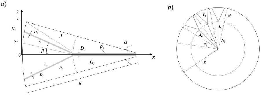
Figure 2 a) Semi-circular sector with a bifurcated top metallic contact. b) Sketch of the distribution of sector of angle α in a single solar cell with a disc-shaped body.
As a part of the optimization process, an aspect ratio
The geometric characteristics of the branched arrangement over the disc-shaped body solar cell, such as the angle α , are defined with the aid of the definition of the number of peripheral sectors N1 That is α = 2πn/N1 determines the distribution of the branched metallic contacts and is given by the following relationship:
where
The aspect ratio of the central sector of length
L0 can be defined considering that the
angle α is approximated as
To define the power loss of the central sector of radius
L0 where occurs the electric current
confluence from the branched contacts is necessary to define the aspect ratio
Following the methodology described in section 2.1, the power loss of the central
sector is defined and consequently, an aspect ratio
Where A0/A1, is defined by Eq.(22).
The total power loss of the geometrical arrangement can be easily expressed by adding Eq.(20) to the power loss of the central sector. The resulting expression defines the contribution of the inserts of length L1 and the electrical current collection of the central sector with the n -contributions of electrical current. This is given by the following expression;
where the term
(A0/A1)2(ϕ0/ϕ1)2
can be defined with the aid of the Eq.22) as a function of
ϕ1 and the width ratio
The occupied area of the metallic contacts in an n -branched arrangement over the circular sector, help us to define the total allocation of the 𝑛-branched arrangement of metallic contacts. The occupied area Ap1 is given by Ap1= ND1L1+ (N/n)D0L0, from this definition, and the lengths L0 and L1, area ratio Φ =Ap1/A1 is defined as:
where
On the other hand, a single solar cell can be modeled as an equivalent circuit with a current generator as a photogeneration system, where the recombination current mechanism is represented by a diode and a series and shunt resistances. The series resistance represents the bulk resistance of the semiconductor, contacts and interconnection. The shunt resistance considers the leakage of electrical current around the edges of the solar cell. This series resistance is desirable to be minimal to improve the collection of electric current generated by the semiconductor material. Minimizing this series resistance improves the fill factor, this is a parameter that evaluates the quality of the current-voltage process, defined with the equivalent circuit of a solar cell (Lee, 2010).
The electric resistance due to the geometric arrangement of the top metallic contacts over the disc-shaped solar cell can be considered as a bulk contact resistance between the semiconductor and metallic contacts that contributes to the resistive power losses over the solar cell, as a first approximation. The branched arrangement defined by the constructal design method can be considered as series resistance (radial contact) and parallel resistances (branched contacts) and expressed as an equivalent series resistance over the semi-circular sector.
From Eq.(7), we can define the equivalent dimensionless electric resistance of the
geometrical arrangement of top metallic contacts, applying the constructal design
method (Huang et al., 2011; Huang, Guo & Ye, 2011; Huang, Guo & Chu, 2011; Morega & Bejan, 2005; Ojeda et al., 2020). This electrical resistance is defined by
evaluating the voltage drop of the constructal element at the point where the
voltage drop in vertical and horizontal directions is maximum. The expression of the
dimensionless resistance, Δψ =
(Vm+
V0)δ/JAρm
is defined with the aid of the areas definition
A0,
A1 and the optimal aspect ratios
where optimal aspect ratios
4. Results
The total power losses for the geometric arrangement of metallic contacts with
respect to geometrical characteristics, defined by Eq.(25) are shown in Figures 3 and 4 for the bifurcated case, n = 2 The value
of the dimensionless parameters as resistivity´s ratio


Figures 3a) and b) show the minimum values of
In order to analyze the influence of the disc size, given by
The resistive power loss presents a double minimum value for two geometric
parameters, associated with the presence of the metallic material,
ϕ1 and the disc size
The optimal length of the metallic contact of the central sector, in a branched
arrangement,
In the following Figures 5 and 6, the influence of the number
n of branched contacts is shown, for a fixed
value of β = 10 degrees and maintaining the same
values of the dimensionless parameters


Meanwhile, in Figure 6, we use the corresponding
optimal value of the geometrical parameter ϕ1
opt where the minimum power loss is presented, for every
n -branched value given in Figure 5, to reveal the influence on the power
losses of the 𝑛-branched contact arrangement and the width ratio
In Figure 6a) the total power losses present a
minimum values for an n -branched arrangement of the
metallic contacts, for the bifurcated case, n = 2 ,
the minimum is presented at
In Figure 6b) we show the corresponding width
ratio
The minimum total power losses
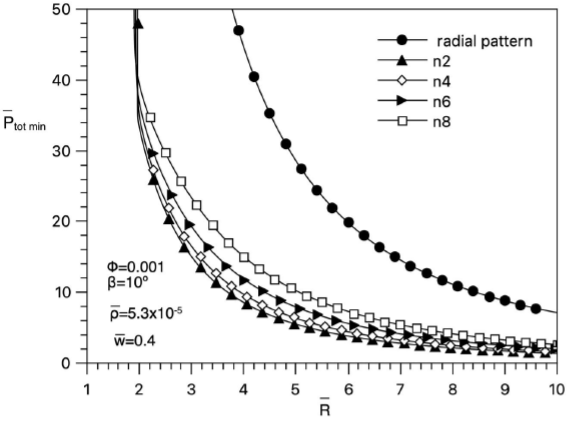
Figure 7 Total power losses of the geometric configuration of the metallic contacts for n branched values.
For a value of
The number N1 of peripheral sectors of area
A1, defined with the aid of the
expression of the angle α , given by Eq.(21), tends to
increase when the size of the disc is also increased. For the bifurcated case at
Finally, the equivalent dimensionless electric resistance of the metallic contacts arrangement, given by Eq.(27), is a function of the optimal aspect ratios of the constructal semi-circular sectors, defined by the minimization of the resistive losses are a function of the number n of branches, geometrical and physical parameters, mainly.
We have fixed the same values of the parameters used in the previous Figure 7, in order to show the equivalent resistance of an arrangement of series and n -parallel resistances. The dimensionless equivalent resistance is shown in Figure 8.
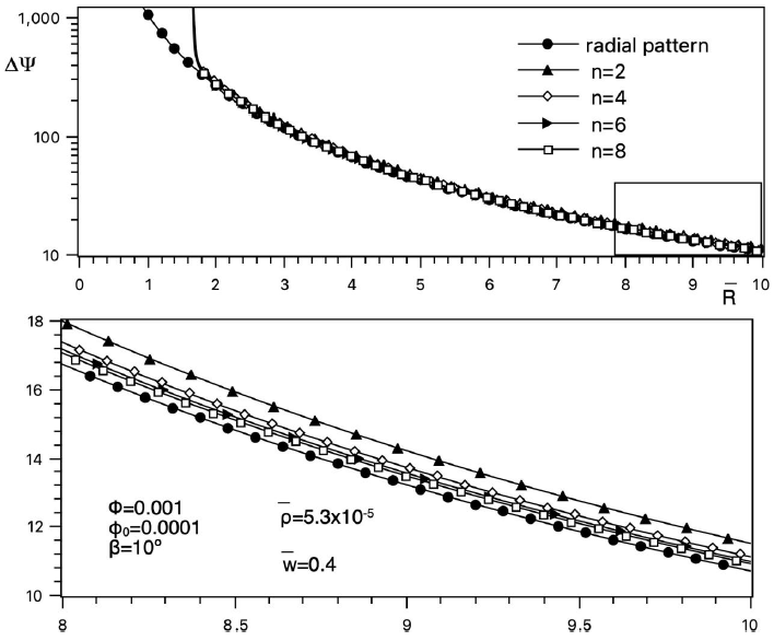
Figure 8 Dimensionless resistance of the constructal assembly of metallic contacts for n branched values.
The dimensionless electric resistance Δψ presents a
divergent value at
The main objective of the present work is to define the geometric arrangement of metallic contacts over a disc-shaped solar cell by the reduction of the associated resistive losses. The bifurcated arrangement of contacts presents the reduced value of resistive losses and consequently an equivalent electrical resistance with which can help to calculate the parameters to evaluate the global efficiency of the arrangement, generally conceptualized as an equivalent electric circuit, presented by a current generator, diode, series resistances that represent the bulk resistance of the semiconductor and contacts materials, shunt resistances that represent the leakage of electrical current.
5. Conclusions
The constructal design method allows designing a tree-shaped metallic contact network
by the minimization of the power loss. The main parameters that allow us to define
this geometry are the allocation of the metallic contact in shape optimized
constructal elements, electrical resistivity´s ratio

