


 nova página do texto(beta)
 Artigo em XML
 Referências do artigo
 Enviar este artigo por email
 Citado por SciELO
  Similares em
SciELO
Similares em
SciELO 
 Permalink
1. Introduction
Cold forming or forging is a highly efficient process for shaping material profiles. A metal plate is creatively deformed within a tooling using a press at room temperature [1-3]. Predicting and controlling elastic recovery (SB, spring back) during bending processes is one of the principal challenges as it depends not only on the bending process parameters but also on the raw material's inherent characteristics and processing [4-8].
Additionally, reducing scrap in die development poses a complex challenge of full importance to tooling designers. [9-14]. Failing to achieve this objective can result in significant issues during part assembly, thus generating additional expenses for tooling adjustments. If recovery cannot be accurately predicted, one must repeatedly attempt to obtain the proper conditions to compensate for the SB [15-18].
In the case of products manufactured using a cold bending process, the standards for quality, specifications, and tolerances tend to be quite stringent. [19, 20], as they are cross-industry [3,21-23]. The performance and dimensional quality of these products can be influenced by various factors, including but not limited to wear and tear of tooling, environmental conditions, production process, and service life [24-27].
When manufacturing, carefully considering the hydraulic press's operating conditions is crucial. Precision operations during the bending process are indispensable factors to keep in mind, particularly regarding the pressing form and method [28-30]. Excessive load is often the cause of premature damage to pre-forming tooling or dies, despite their ability to withstand high levels of stress and wear due to their design. Despite being classified as perishable tooling, they are engineered to resist fatigue and friction contact [1, 31-34].
This research aims to establish a precedent for operating an in-made house horizontal hydraulic press and to acquire a deeper understanding of achieving the best possible conditions for effectively making bends, precisely 90° or V-bends hot-rolled carbon steel plate. It is crucial to optimize the press's performance, ensuring that it operates with maximum efficiency while avoiding exceeding the maximum pressure limit of 3000 psi. Furthermore, we must consider the necessary compensation for spring-back to prevent deviations from the desired specifications and maintain precise geometrical tolerances. Maintaining a deviation of no more than 1° from the nominal angle during the bending process is crucial. This guarantees the final component's quality and subsequent procedures success. To prevent any deviations in future processes and ensure the smooth operation of the finished piece, it is essential to compensate for spring-back adequately.
2. Materials and experimental details
The bending process was carried out at a 90° angle of plate 6.963*2* – inches (large, width, and thick) hot-rolled carbon steel (by ASTM A-36). The bending procedure was performed by the method outlined in the reference [35] and illustrated in Figure 1.
Material preparation: ensure the plate has the correct dimensions and strength to withstand the V-bending process.
Bending tool selection: select the appropriate V-bending tool for the size and thickness of the material to be bent. The bending tool can be a bending die or a bending press.
Material positioning: place the plate on the bending tool, ensuring that the bending line is aligned with the V-shaped line of the die. As shown in Figure 1 a).
Bending tool adjustment: It is necessary to adjust the bending tool to achieve accurate bending and proper bending force. Setting the tooling to apply the required bending force and accomplish the correct bending angle is essential.
Bending: To bend the workpiece accurately along the V-line shown in Figures 1 b) and 1 c), the bending tool must be precisely actuated to apply the required force.
Results verification: verify that the angle and quality of the bend are adequate, as shown in Figure 1 d).
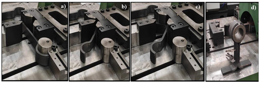
Figure 1 The Manufacturing process of the arm for pendants by bending: a) Positioning, b) Bending, c) Piston retraction, d) Manufactured part.
The process above was done at Martin Sprocket & Gear Inc., a specialized company that manufactures helical worm equipment for the transporting and handling bulk materials. This equipment is highly prevalent in various industries, including food, mining, agriculture, and pharmaceuticals, where they function as mixers, dozers, elevators, or agitators based on the worm principle. Figure 2 displays the purpose of the sub-assemblies to prevent the helical element from deflecting, thus reducing friction between the component and the main housing. Such a sub-assembly carries two pieces called arms or pendants, obtained by cold bending.

A 2k factorial experiment design was conducted to determine the press operating conditions necessary for obtaining a 90° bending (Fig. 1 c). The variables in this DOE were the press pressure and the time of the pressure permanence before the piston recoil. Each variable had four levels (k=4). In Figure 3, the variables are summarized in the diagram.

The pressure applied to a material is the principal factor defining its deformability. Hence, the pressure was considered one of the controlling variables during the testing process; this experimental analysis was done under four levels in descending order from 3000 to 1500 psi with 500 psi steps. The second factor was the permanence time before the piston retraction, while the pressure was maintained to compensate for the SB. Likewise, four levels were tested in a permanence time, from 0 to 1.5 seconds with 0.5 seconds’ step. From the above, we have 24=16, and two tests were made for each case of experimentation, giving a total of 32 tests.
For each test, the angle after the bend was measured with a Wixey digital goniometer, model WR300 Type 2, as seen in Figure 4. The measurements were utilized to compute the deviation from the nominal angle, as the objective is to achieve a bent workpiece with a 90° angle. The statistical analysis of the data was performed by ANOVA using NCSS statistical software (NCSS 2021, statistical software, Kaysville, Utah, USA). This analysis considered a confidence level of 95%, with a type of bilateral interval.

3. Results and Discussions
Table 1 shows the angles obtained after subjecting each plate to bending. It is important to remark that variables such as pressure and permanence time before the piston retraction were considered during the process.
Table 1 Value of angles measured for each experimental condition.
| PRESSURE (psi) | PERMANENCE TIME DURING THE PRESSURE | |||||||
|---|---|---|---|---|---|---|---|---|
| t 1 = 0 s | t 2 = 0.5 s | t 3 = 1 s | t 4 = 1.5 s | |||||
| P1 = 3000 | 89.3 | 89.5 | 89.9 | 89.9 | 89.9 | 89.9 | 89.8 | 89.7 |
| P2 = 2500 | 89.6 | 89.4 | 90.2 | 89.9 | 90.5 | 90.5 | 90.4 | 90.1 |
| P3 = 2000 | 89.4 | 89.7 | 90.3 | 89.8 | 90.3 | 89.8 | 90.3 | 90.1 |
| P4 = 1500 | 89.3 | 89 | 89.4 | 89.4 | 89.3 | 89.5 | 89.4 | 89.3 |
To quantify the recovery in the plate, the recovery factor K r was calculated by the following ratio [36]:
Where:
β i is the value of the bending angle with load applied, which for the case study is 90°.
β f is the resulting angle after removing the load (shown in Table 1).
The Kr values obtained are presented in Table 2; in this case, K r values close to 1 imply an absence of elastic recovery, resulting in SB approaching zero. In contrast, if SB values move away from zero, there is an increase in the recovery effect.
Table 2 Recovery factor K r.
| PRESSURE (psi) | PERMANENCE TIME OF THE PRESSURE | |||||||
|---|---|---|---|---|---|---|---|---|
| t 1 = 0 s | t 2 = 0.5 s | t 3 = 1 s | t 4 = 1.5 s | |||||
| P1 = 3000 | 0.992 | 0.994 | 0.999 | 0.999 | 0.999 | 0.999 | 0.998 | 0.997 |
| P2 = 2500 | 0.996 | 0.993 | 1.002 | 0.999 | 1.006 | 1.006 | 1.004 | 1.001 |
| P3 = 2000 | 0.993 | 0.997 | 1.003 | 0.998 | 1.003 | 0.998 | 1.003 | 1.001 |
| P4 = 1500 | 0.992 | 0.989 | 0.993 | 0.993 | 0.992 | 0.994 | 0.993 | 0.992 |
Figure 5 shows the values corresponding to the factor K r . According to the confidence level established at 95%, the data show remarkable adherence to the normal distribution line, thus indicating an approximately normal distribution. Settings are evenly distributed above and below zero. Since the value p exceeds the limit of 0.05, as can be seen in Table 3, it can be concluded with statistical certainty that the data exhibit a normal distribution. Therefore, the results are statistically significant for further analysis.

Table 3 Normality test results.
| Normality Test | Prob. Level | Decision |
|---|---|---|
| Shapiro-Wilk W | 0.1325 | Can´t reject normality |
| Anderson-Darling | 0.0958 | |
| D'Agostino Skewness | 0.6559 | |
| D'Agostino Kurtosis | 0.1084 | |
| D'Agostino Omnibus | 0.2495 |
The results of the variance analysis (ANOVA), a statistical technique employed to detect significant discrepancies between the averages of two or more groups, are shown in Table 4. This study examined two primary factors: pressure and time, as previously mentioned.
Table 4 Statistical values (Analysis of Variance).
| Analysis of Variance Table for Kr------------------------------------------------------------ | ||||||
|---|---|---|---|---|---|---|
| Source Term | DF | Sum of Squares | Mean Square | F-Ratio | Prob Level | Power (Alpha=0.05) |
| A:Pressure_psi_ | 3 | 0.000344625 | 0.000114875 | 31.69 | 0.000001* | 1.000000 |
| B: Time_s_ | 3 | 0.000195125 | 6.504167E-05 | 17.94 | 0.000023* | 0.999943 |
| AB | 9 | 5.8125E-05 | 6.458333E-06 | 1.78 | 0.150238 | 0.570971 |
| S | 16 | 5.8E-05 | 3.625E-06 | |||
| Total (Adjusted) | 31 | 0.000655875 | ||||
| Total | 32 | |||||
* Term significant at alpha=0.05
The analysis reveals that the pressure has a significantly high F-ratio value of 31.69. In ANOVA, the F ratio compares the systematic Variance resulting from the tested factors against the random Variance, which stems from unexplained variations. A higher F-value indicates a higher probability that group differences are systematic rather than random.
Figure 6 displays a chart depicting the effect of the control factors (pressure and time) on the response variable (K r value) through a presentation of the main effects. This graphical representation visualizes how each factor impacts the system's response.
Achieving a Kr value of 1 during the bending process is crucial because it signifies that the part's appropriate and final bending angles are a perfect match. A K r value of 1 indicates that the component has been bent precisely to the desired angle, thereby minimizing any discrepancies that may compromise the quality of the end product.
In Figure 6 a), it can be observed that K r reaches minimum deviation with a value of 0.9995, which is close to the ideal value of 1 when the pressure is at 2000 psi. This result suggests that pressure has a significant impact on bending accuracy.
Figure 6 b) represents the value of K r as a function of the permanence time of the load (pressure). Notably, a permanence time of 1 second before piston retraction also produces a minimum deviation of K r , reaching a value of 0.99963. This observation indicates that time is another crucial factor that can optimize bending accuracy.
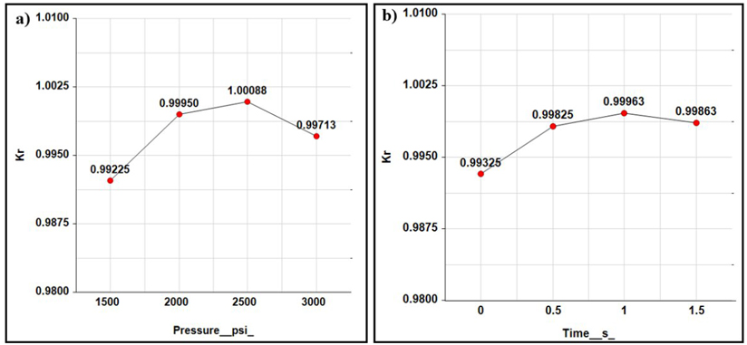
Figure 6 Plots of the main effects: a) recovery factor as a function of pressure and b) recovery factor as a function of time.
The data in these graphs indicate that the most precise bending can be achieved by combining 2000 psi pressure and 1 second time. It's important to comment that these values might fluctuate due to other factors, like the material type and machine specifications. Therefore, it is always recommended to perform additional experiments and fine adjustments to optimize the bending process in each case.
Considering the variance analysis presented in Table 4, which indicates that pressure is the most significant factor, Figure 7 a) displays the interactive effect of the control variables by illustrating the K r behavior based on the pressure function. In the graph, there are three conditions for which K r is very close to 1, for a pressure of 2000 psi with a time of 0.5 and 1 s, and at 2500 psi at 0.5 s. These three conditions are confirmed as observed in the surface response graph shown in Figure 7 b).

Figure 8 shows a comparative box plot of two process variables to ascertain the most favorable combinations to produce optimally formed parts. Upon examining Figure 8 a), it can be inferred that the conditions most conducive for attaining an optimal K r value of 1 lie between 2000 and 2500 psi. The data underscores this inference by showing a median K r value of less than 1 at 2000 psi and a value exceeding 1 at 2500 psi. Consequently, these two pressure points represent the highest probability of achieving the ideal K r value. Notably, the 2000 psi condition exhibits a normal distribution slightly more centralized than that at 2500 psi.
On the other hand, Figure 8 b) provides a chronological plot of K r values. Notable observations at the timestamps of 0.5, 1, and 1.5 seconds reveal a certain reproducibility level where K r is proximate to 1. A wider distribution around the 1 s mark contrasts with the 0.5 s mark. Yet, most results cluster around a K r value of 1, rendering 1 s a suitable choice. The 1.5 s condition, however, does not seem to represent the desired outcomes and would lead to an increased cycle time in the process.

The results show that the two reliable combinations are 2000 psi/1 s and 2500 psi/0.5 s. By selecting these sets of parameters as optimal and accounting for any deviations from the desired 90º angle, we can guarantee the ability to achieve bending with a ±0º 20' tolerance, categorized as type C according to ISO 2768's (International Organization for Standardization (1989), ISO 2768-1: General Tolerances: Tolerances for Linear and Angular Dimensions Without Individual Tolerance Indications). It should be noted that such tolerance is lower than required in the plane (±1º) for the part manufacturing. Furthermore, applying 2000 and 2500 psi pressures would lead to a remarkable 16.66% and 33.33% reduction in the press operating pressure, respectively. It is worth highlighting that, for the bending process, the adjustment of the press is not the only parameter that influences the final angle obtained; other variables affect the final result, such as the punch's radius, the material, the thickness, and the mechanical behavior during the deformation process, among others [4, 9, 10, 12]. However, the objective of this work focused on obtaining the appropriate dam operating conditions, and the expected result of this improvement is an increase in the durability of components subjected to friction, reducing their wear and minimizing the probability of fatigue failure in mechanical elements [26]. It is also expected that the temperature levels in the hydraulic unit are below the critical level to avoid overheating and the adverse effects it generates.
4. Conclusions
The findings of this study illustrate the viability of producing a 90º bend in a hot-rolled carbon steel plate (ASTM A-36) with dimensions of 2 inches in width, 3/4 inches in thickness, and 6.963 inches in length, utilizing an in-house fabricated press.
Effective bending can be achieved by either applying a pressure of 2000 psi with a dwell time of 1 s before retracting the piston or utilizing a pressure of 2500 psi with a waiting period of 0.5 s. These operational conditions comply with the tolerance specified for type C in ISO 2768-1.
The applied pressures represent a decrease of 17% and 33%, respectively, about the maximum pressure employed. These reductions are anticipated to enhance the lifespan of tools, pistons, and dies due to decreased wear and fatigue. Moreover, the established operating parameters facilitate the creation of a tool design that aligns with commercially available matrices.
Another practical implication of these operational parameters is the expectation that temperature levels in the hydraulic unit will not reach critical thresholds, thereby mitigating risks associated with overheating. The importance of thoroughly validating these final considerations cannot be overstated. However, it's worth highlighting that these analyses, while of potential interest, were deemed tangential to the study's primary objective and were not included within its scope.

