


 nova página do texto(beta)
 Artigo em XML
 Referências do artigo
 Enviar este artigo por email
 Citado por SciELO
  Similares em
SciELO
Similares em
SciELO 
 Permalink
1. Introduction
Currently, most of the main global automotive enterprises tend to virtualize all the components and systems of the vehicle in each vehicle platform to evaluate them before each assembly is built. This is a cost avoidance that all the automotive brands want. It is important to mention that not all automotive systems are well represented in the virtual world due to the complexity and the variety of all the components' spectrum; for example, the automotive wiring and cable coverings, usually the mechanical information about those coverings are used applying an average to get a rough approximation. However, the mechanical behavior of the wire harness is complicated by its complex geometry and the number of materials involved. As these are prestressed and loaded in service, a complicated stress state condition arises that combines the effects of tension, torsion, bending, and shear along with multiple non-linear phenomena such as cable-to-cable or cable polymer motion (the relative motion between cables), contact, friction, plasticity, and large deformation.
One of the most failed assessments in the assembly plant is the installation of high-voltage cables. These cables face ergonomic problems due to difficulties in the assembly vehicle line cyclic processes, where mechanical stress is being carried out above the established values [1-3], affecting pre-productive and productive build stages to the overall assembly plants [4]. Some solutions to wiring and cables are being studied to help with creative ideas to solve the main difficulties presented in the assembly process. One of them is manual installation, e.g., a solution is the use of automation to achieve hybridization of human-robot collaboration (HCR), and this hybridization helps to alleviate the installation effort [5, 6]. Furthermore, implementing new technologies can significantly increase the automation degree and product quality by using intelligent manufacturing technologies to overcome the challenges and drawbacks of optimization solutions and the current state of production [7]. The main factors that generate harness installation difficulties are listed below:
The human-manual process of constructing an automotive harness, for example, the distance between turns of tape, number of turns, and tape speed [8-11].
The environment in the place where the harness is installed on the vehicle, for example, areas with low temperatures where greater installation problems have been demonstrated, causes damage to operators, their perception of rigidity increases, and it is sometimes necessary to install cable heaters to facilitate assembly [12].
Violation of double radii in the harness design causes excessive effort in handling very tight curves [13, 14].
Material and number of wires in the wiring where the lower the number of wires, the greater the resistance to being bent has been tested [15].
Type of insulating material (first coating). This refers to material selection due to flexibility and temperature resistance [16].
Types of tapes for the protection of high voltage cables made with materials that are more rigid than others [17-20].
All the mentioned factors are agents that cause overexertion in installing high-voltage cables, all listed arbitrarily, without implying their level of importance by their position. It can be said, therefore, that the case of greatest ergonomic criticality would be that high voltage cable that combines all the above characteristics. This research will focus on the selection of coverings and the relationship between length and the ergonomic performance of a high-voltage cable. After considering the information provided, it is important to ask the following questions:
Could the selection with ergonomic criteria of coverings for an automotive high-voltage cable directly relate to deformation resistance that could impact the performance in the assembly plant installation?
Could the length of an automotive high-voltage cable directly relate to the deformation resistance that could impact the performance in the assembly plant installation?
The research will focus on the selection of coverings and their relation to the length of high-voltage cables or any electrical harness. This focus is motivated by the thorough examination of other factors listed in installation issues in previous studies [21-24]. The innovative aspect of this research lies in addressing an area that has not been extensively evaluated in the early design stages of an engineering process: the selection of coverings [25]. This gap exists due to insufficient information on the mechanical characteristics of automotive tapes. By conducting this evaluation, the research aims to prevent the creation of branches and covered wiring that, despite being feasible in Computer-Aided Design (CAD) software, are difficult to handle during installation in assembly plants. Such difficulties can lead to serious production problems, including ergonomic issues for operators [27], work accidents [28], and compromised product quality, prompting companies to invest significant resources in redesign efforts.
Some authors [29] did extensive research on the dynamic stress and post-breakage behavior of a prestressing strand and proposed a finite element model that is generally useful to study the global response of the strand, along with many localized phenomena that have a strong influence on their performance, but which are difficult to capture either experimentally or through closed-form analytical models [30, 31]. However, investigations into certain behaviors, such as cable breakage, require a relatively large or full-scale model to adequately develop contact and friction conditions [32]. Through a study of this state-of-the-art, others describe the manufacturing processes and analyze where the manufacturing complexity of the component originates. Another work that provides a process to characterize the behavior of the wiring harnesses was developed by Ehsan Taghipour et al. [33-35], who explained the analysis and computational modeling to evaluate electrical wires, especially dynamic mechanical analyses to investigate the viscoelastic properties of self-adhering synthetic rubber, and to identify the parameters of a viscoelastic model that be accurate and represent the frequency dependent on dynamic mechanics [36-38]. Therefore, the intention and improvement of this research are to provide predictions according to some scenarios studied without being in a current application. Consequently, this research aims to feed the SIMSOLID finite element software database to improve the accuracy of the mechanical analyses and to predict the behavior of the cables in a shorter time before the vehicle assembly process, correcting and improving the components so that they can be installed ergonomically, saving time and without the associated cost.
This manuscript is organized as follows: Section 2 details the equations employed to calculate the parameters to characterize the mechanical properties of the high-voltage cables. Section 3 details the methodology and design of experiments, including the geometry of the high-voltage cable and the boundary conditions used. Section 4 presents the characterization of the properties of the high-voltage cables. Additionally, it presents the results of the finite element method of the high-voltage cable and compares them to the experimental results. Finally, in Section 6, conclusions are summarized.
2. Methods
The material under study does not exhibit a linear response, implying that its behavior is best described by a non-linear elastoplastic model, which considers the material's ability to deform under stress and its tendency to retain some plastic deformation after removing it. Regarding the material properties characterization of the cable and its protective covering, it is necessary to analyze the force-deflection data and convert it into stress-strain data. This will allow for calculating important parameters such as the Elasticity Module, Poisson Ratio, and Yield Stress for the linear region of the cable's behavior. Calculating the non-linear region's strength coefficient and strain hardening exponent is also important to completely understand the cable's mechanical properties. The deflection cantilever beam equations show the relationship between the force-deflection and stress-strain curves [33].
The elasticity module E, which was only used for the linear region, was calculated as follows:
Where:
Substituting I in equation 1:
Recognizing the non-linear behavior of an elastoplastic material is crucial to comprehending the two primary equations that describe the strain-stress curve. The first region is divided into the elastic and non-linear regions, separated by the yield strength. By grasping the concept of these regions, one can gain an in-depth understanding of the behavior of an elastoplastic material under various conditions.
According to the behavior of the cables and coverings, Hollomon's proper equation used in this manuscript to get the stress-strain charter was defined by Power Law given by Ehsan Taghipour et al. [33].
Total stress is defined by the stress at yield plus the strain hardening behavior in the function of strain, strength coefficient, and strain hardening exponent values. Thus, starting with the elastic region, the stress could be calculated with equation (5), defining the lineal region in the force-deflection plot.
Once it was calculated the stress and the elasticity module for each point over the linear region, it is also possible to calculate the strain in the elastic region with equation (6):
At this point, the elastic region was determined, so now it is possible to proceed with the non-linear region, calculating the exponent strength coefficient and strain hardening to get the non-linear behavior. The first point to calculate n and K that will be used in the elasticity module in the non-linear region is to follow the procedure extracted from Ehsan Taghipour et al [33].
Where E t is the tangent elastic module at yield, defined by the numeric derived from the last two points of the elastic region, and the linear estimation of all points of the elastic region defines E.
Once the previous values were obtained, it is necessary to calculate a first estimation of K.
The correct value of the exponent strength coefficient and strain hardening is not yet found; the initial. E t It is a small portion of the linear ending and non-linear starting of the curve, and it will probably not be the correct one. It is needed to find the correct direction of the curve where the unique value known is the final maximum deflection.
Hence, it is indispensable to use the initial values exponent strength coefficient and strain hardening to find the correction of E t but now, in the non-linear region E n .
Where E n is the estimation of the elasticity module at the non-linear region, σ is the stress in the small portion of the E n , and σγ is the stress at the yield point.
Finally, it is necessary to iterate the values obtained from the previous calculations into the Finite Element Method (FEM) to get an answer and get the maximum virtual deflection. Thus, if the result with the previous values is accepted with an error of 0.005 between the virtual deflection and the real deflection, it can be considered the characterization finished for that sample. The error is calculated with the following equation.
3. Methodology
The methodology implemented in this research is explained as follows:
Define the experimental conditions to bend the cables and obtain values of force vs. deflection using the cantilever beam test.
Perform force/deflection experiments for each combination of lengths and protection covering of the high-voltage cables.
Characterize the values from the force-deflection test to incorporate them into the equations, resulting in the stress-strain evaluation. The latest brings experimental support to understanding the behavior of the cables in terms of the elasticity module, Poisson ratio, strength, coefficient, and hardening component.
Input the obtained values into the CAE software (E, υ, n, and K) for the mechanical analysis.
Iterate the values obtained from the CAE analysis to achieve a maximum deflection consistent with the physical model.
The methodological steps are summarized in Figure 1.

3.1 Deflection test
When describing the deflection of a cantilever beam, it refers to the bending or displacement resulting from an external load applied to the beam's free end. A cantilever beam is a structural element fixed at one end but extending freely into space, capable of carrying loads at its unsupported end. The cantilever beam fixation technique was necessary to accurately measure the deflection force and generate a precise bending curve that could approximate the behavior of the cables in real-life installation scenarios. The tensile test was performed using the Instron tensile machine model 3400 Series of 1 kN, as highlighted in Figure 2. The procedure carried out within the laboratory took place under controlled conditions with a pressure of 1 atmosphere and a temperature of 23 °C. Two samples were prepared with 100 mm, 200 mm, and 300 mm dimensions.

During the cantilever beam deflection experiment (see Figure 3), a high-voltage cable was subjected to a rigorous test to determine its strength and durability. The process involved securing the cable with a tensile grip, leaving a 50 mm distance between the grip and the cable. A steel cable with a mobile grip on one end applied tension in a diagonal direction, causing the high-voltage cable to deflect. The mobile grip was centered directly over the fixed point, and it contained a load cell model 2519-105 that was set to move at a speed of 300 mm/min.

A high-voltage cable comprises a central core of conducting material surrounded by an insulating layer that protects the conductor from external influences. The cable characteristics are presented in Table 1. The insulating layer is further enclosed by a shielding layer that provides additional protection and prevents electrical interference (see Figure 4). Together, these three components make up the structure of a high-voltage cable, which is essential for the efficient and safe transmission of electrical power over long distances.

Table 1 High-voltage cable technical characteristics.
| Conductor | Core | Screen | Cable | |||
|---|---|---|---|---|---|---|
| Construction | Diameter | Wall thickness | Diameter | Construction | Wall thickness | Diameter |
| N x Ømax. [mm] | [mm] | [mm] | [mm] | N x N x Ømax. | [mm] | [mm] |
| 1600 x 0.21 | 10.5 | 0.71 | 12.2 | 24 x 9 x 0.21 | 0.88 | 15.2 |
The tape used to cover the cables is Coroplast 8375-X (see Figure 5b); these polyester cloth tapes are designed for wire harness applications. The heat-resistant PET-cloth tape is designed for a solid and spiral taping of cable sets and wire harnesses with abrasion-resistant and high tensile strength properties. For the experiments, the tape was manually added in a spiral conformation with an overlap of approximately 50%. The properties of the tape are presented in Table 2.
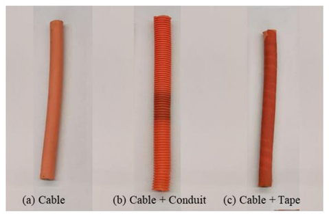
Figure 5 High-voltage cable and high-voltage cable with cover samples. (a) Cable, (b) Cable with conduit, and (c) Cable with tape Coroplast 8375-X
Table 2 Dimensions and mechanical properties of tape Coroplast 8375-X for high voltage cables.
| Carrier | Thickness | Widths | Length | Tensile Strength | Elongation at break |
|---|---|---|---|---|---|
| [mm] | [mm] | [m] | [N/cm] | % | |
| PET-cloth | 0.27 | 9, 15, 19 and 25 | 25 | 240 | 27 |
On the other hand, the Conduit is a protective enclosure for high-voltage cables, providing insulation and safeguarding the cables from external environmental factors, mechanical damage, and potential heat sources, as presented in Figure 5c. In this case, the Conduit employed is made of a high-heat impact modified Polypropylene (MPP). For high-voltage cable conduits that require resistance to high heat and impact, Modified Polypropylene (MPP) is commonly used. Modified Polypropylene is a type of Polypropylene that has been enhanced with additives or modifiers to improve its performance characteristics. These modifications may include reinforcements, flame retardants, and impact modifiers, making it well-suited for applications where both high heat resistance and impact strength are crucial. Some important parameters are tensile strength greater than 27.5 MPa, elongation at break >50%, and 1.15 g/cm3 density.
The proposed experiment was developed using high-voltage cables and mechanical protection (Tape and Conduit). The experiments utilized various combinations of cable length and covering, listed in detail in Table 3 for easy reference.
4. Results and discussions
4.1 Characterization of the properties of the high-voltage cables: force/deflection experiments
The experimentation process described previously involved utilizing the prepared cables and setup. The experiments was based on this plan, aiming to study the force/deflection behavior. The following section will provide a detailed discussion of the results and outcomes of the experimentation process. The behavior of forces and deflection for covered and uncovered 100 mm cables is illustrated in Figure 6. The deflection range for all tests is between 0 and 1. The graph depicts the initial linear behavior, followed by the non-linear start point at approximately 0.1 mm, and ultimately, the non- linear behavior until 1.0.
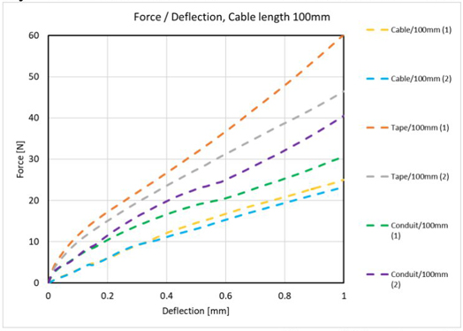
Figure 6 Experimental Force/Deflection responses for a high-voltage cable length of 100 mm and various covers.
The data plotted in Figure 7 illustrates the relationship between the forces applied and the deflection of two 200 mm cables, one with and one without coverings. The deflection is the total amount experienced during all tests, expressed from 0 to 1 mm. The data distribution demonstrates that the cables exhibit initial linear behavior, followed by non-linear behavior starting at approximately a deflection of 0.1 mm. The non-linear behavior persists until the cable reaches a deflection value of 0.8 mm. This indicates that the cable has a soft behavior, meaning that the force required to bend the cable is not completely linear.
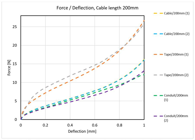
Figure 7 Experimental Force/Deflection responses for a high-voltage cable length of 200mm and various covers.
The results presented in Figure 8 depict the relationship between the forces applied to 300 mm cables and their corresponding deflection values, both with and without coverings. The deflection values range from 0 to 1 mm and are cumulative for all the tests performed. The graph shows the cable's initial linear behavior and a non-linear start-point at approximately 0.05 mm deflection. Subsequently, the cable's behavior becomes increasingly non-linear until it reaches deflection values ranging from 0.1 mm to 0.9 mm, indicating softer behavior. The force response required to bend the cable becomes linear during this stage. The difference between the cable curve before this stage and the subsequent one is significant, emphasizing the cable's changing behavior.

4.2 Computation of effective properties through force-deflection values
The equations presented were utilized to analyze the mechanical behavior of 100 mm cables. The values of ε and σ were charted, and the acquired data was used to provide the necessary curve information to create a 3D model and fully characterize the behavior of the cable. Figure 9 displays this behavior and serves as a visual aid to better understand the cable's mechanical properties. In this case, the comparison of cable, tape, and Conduit as it is shown that the cable with Conduit is deformed with less stress, the cable without protection in second place, and finally, the cable with tape has the stiffness behavior; the deformation increases as the reaction of the force applied to bend it.

Figure 10 depicts the behavior of the 200 mm cables based on the equations presented earlier in Section 2. The corresponding mechanical behavior is obtained through the values of ε and σ and presents the curve information to characterize the cable. When it comes to these 200 mm cables, the behavior of the cable without protection and the cable with tape had more similarities when compared to the cable with Conduit. This similarity is related to the relation between the length and covering stiffness of the cables. The comparison between cable, tape, and Conduit results indicates that cable with Conduit experiences less deformation under stress, followed by cable without protection. The stiffness behavior of the cable with tape is similar to that of the unprotected cable. It was observed that the degree of deformation increases with the magnitude of the applied force used to bend the cable.

Now, the attention goes to analyzing the behavior of 300 mm cables. Thus, Figure 11 displays the data generated by those equations, showing the mechanical behavior of the cables. The data collected from these cables could be used to characterize them. Interestingly, the behavior of the cables without protection, with tape, and in Conduit showed similar patterns. The length of the cables and the stiffness of their coverings may be closely related, which could explain these similarities. In this case, the comparison of cable, tape, and Conduit as it is shown that the cable with Conduit is deformed with much less stress, followed by the cable without protection, and in this experiment, cable sample (2) and tape experiment (1) have almost the same behavior, it is shown that the deformation against the force is not the most important factor, in this case, the length support to reduce the stiffness of the cable.

4.2 Numerical simulation for high-voltage cables
The numerical simulation is required to complete the characterization, thus involving the values obtained from the equations and calculations previously presented. The next step is to assess whether the stress-strain curve calculated yields a deflection greater or shorter than the experimental deflection. This assessment is necessary to determine whether adjustments need to be made to the values of E n , n, and K. The decision-making process is based on a decision tree (see Figure 12) and considers various criteria to determine the most accurate and reliable values for these parameters.

The proposed methodology for this research involves obtaining the accurate stress-strain curve for each high-voltage cable through an iterative process, and these values are summarized in Table 4. Once the values are obtained, they are subjected to a Finite Element Method (FEM) analysis. SIMSOLID ver. 2022.2 - a simulation software application that performs structural system statics, dynamics, and thermal analyses - was employed. SIMSOLID employs fully featured solid geometry models in its analysis and does not use a mesh, relying instead on breakthrough extensions to the theory of external approximation for its computational engine. One of the unique features of SIMSOLID is its multi-pass adaptive analysis, which allows for the control of solution accuracy on a global or part-local basis. Another core feature of SIMSOLID is its use of decoupling geometry functions, which enables the software to perform complex simulations with high accuracy.
Table 4 Mechanical properties for the high-voltage cable and the coverings under test
| Cable 100 mm | Tape 100 mm | Conduit 100 mm | ||||||
|---|---|---|---|---|---|---|---|---|
| n | k | σ y | n | k | σ y | n | k | σ y |
| 0.9572 | 34.2801 | 0.8535 | 0.9257 | 59.6312 | 2.0627 | 0.8762 | 9.2510 | 0.5174 |
| E [MPa] | E t [MPa] | E n [MPa] | E [MPa] | E t [MPa] | E n [MPa] | E [MPa] | E t [MPa] | E n [MPa] |
| 40.7318 | 33.8710 | 37.1987 | 84.3637 | 52.0234 | 72.0562 | 15.8626 | 9.9846 | 12.1132 |
| Cable 200 mm | Tape 200 mm | Conduit 200 mm | ||||||
| n | k | σ y | n | k | σ y | n | k | σ y |
| 0.85691 | 33.9808 | 0.4993 | 0.7493 | 30.9930 | 0.8018 | 0.7756 | 5.3521 | 0.1450 |
| E [MPa] | E t [MPa] | E n [MPa] | E [MPa] | E t [MPa] | E n [MPa] | E [MPa] | E t [MPa] | E n [MPa] |
| 80.2298 | 51.4362 | 58.5717 | 140.379 | 81.5562 | 77.9849 | 19.5968 | 10.6925 | 11.6695 |
| Cable 300 mm | Tape 300 mm | Conduit 300 mm | ||||||
| n | k | σ y | n | k | σ y | n | k | σ y |
| 0.9463 | 75.0241 | 0.2000 | 0.8576 | 65.3165 | 0.3308 | 0.9997 | 26.9826 | 0.0699 |
| E [MPa] | E t [MPa] | E n [MPa] | E [MPa] | E t [MPa] | E n [MPa] | E [MPa] | E t [MPa] | E n [MPa] |
| 110.9552 | 53.8720 | 99.1912 | 183.056 | 126.3494 | 133.6890 | 27.0262 | 19.7772 | 27.0135 |
The experiment was designed meticulously with specific characteristics to ensure accuracy and reliability. The International Metric System was used throughout, with a non-linear material and a geometry model in the form of a cylinder created to simulate a solid cable. The connections were set up automatically, and the modal analysis was conducted using 11 modes. The cable was fixed at the left-hand face, and the transient dynamics analysis was set with an increase-decrease time function, where a force was applied on the right side of the cable in the Y-axis direction. It is crucial to note that certain factors cannot be fully accounted for when running a numerical simulation of a physical model. For instance, numerical simulation fails to consider the glue's resistance, air friction, gravity, and the space between the coverings and the cable. In this experiment, the cables are examined as a bundle, and the behavior of the internal elements is evaluated. These simplifications are necessary to streamline the model and make it easier to understand.
Now, the attention goes to illustrating the cable experimental sample and a numerical experiment conducted in SIMSOLID. The cable experimental sample serves as a tangible model for testing and analysis. At the same time, the numerical experiment carried out in SIMSOLID enables the simulation of various conditions and scenarios that may not be possible or safe to replicate in real-life testing. It is important to note that the numerical experiments have experienced a deformation on a 0.4:1 scale. This is due to the current limitations of computer resources, which aim to minimize the chances of any deformations. However, the results of each cable length and cable covering are presented in detail as follows. The analysis of high-voltage cables requires accurate characterization to ensure the safety and reliability of the cables. In this regard, the results obtained from two samples of each cable covering 100 mm, 200 mm, and 300 mm lengths show that the difference between the experimental and CAE values is less than 0.005, confirming the characterization's reliability. The iterative approach to obtain the characterization is the key factor in validating the experimental values. The 3D virtual analysis also supports the data and the initial statement about the mechanical behavior of the high-voltage cable.
Regarding the covering force and displacement, the experiment design applied force to individual cables to determine their final deflection. The results of the experiment showed that a cable length of 100 mm had a deflection of 36 mm (Figure 13a), while a cable length of 200 mm had a deflection of 94 mm (Figure 13b). The final test was conducted on a cable length of 300 mm, which had a deflection of 172 mm (Figure 13c). These findings provide insight into the relationship between covering force and displacement and can be used to inform future experiments in this field.
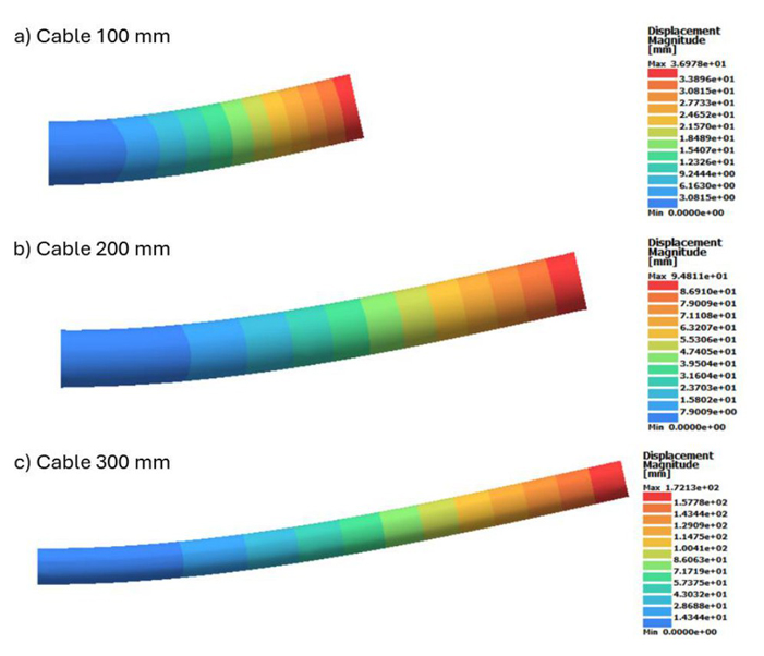
Figure 13 Numerical simulation of the beam deflection at SIMSOLID software. It presents the maximum displacement magnitude for the diverse cable lengths (a) 100 mm, (b) 200 mm, and (c) 300 mm.
The results obtained from the latest iteration indicate that the error rate is less than 0.5% across all cases. This implies that the initial statement has been successfully met, and the high-voltage cables' curve has been determined. This finding is crucial as it allows for predicting the mechanical behavior of the cables during vehicular ergonomic CAE analysis. It is important to note that this study stands out from Ehsan Taghipour et al. work [33] due to the unique approach and methods employed.
Figure 14 presents the relation between the force and the length and covering; for example, the Tape 100 mm needs more than ~47 N to bend; this commonly in the automotive industry is a non-ergonomic value [9], and this is the objective of this research, to get data to evaluate different kind of environments to it could be possible to select the best configuration of length/covering of each portion of the routing before to manufacture the high-voltage cable and assemble on the vehicle avoiding waste of time and money.

5. Conclusions
This manuscript presented an innovative and highly specialized process for carrying out materials characterization and mechanical assessments of a wide range of cables with different types of coverings. The primary purpose of these coverings is to provide high-voltage cables with protection against harsh or abrasive surfaces. By using this method, it is possible to determine the efficacy of these coverings in safeguarding the cables against damage and degradation and assess the overall mechanical properties of the cables themselves. Due to practical and economic limitations, it is impossible to experimentally measure the stiffness for the wide range of cross-sections in real wire harnesses. Therefore, simulating the critical cross-sections of the wire harnesses using Finite Element (FE) is a more practical and cost-effective approach. Hence, the cost and time needed for the mechanical characterization of wire harnesses are significantly reduced by employing the appropriate numerical simulation technique.
Regarding the numerical simulations, it concludes when the discrepancy between the experimental deflection and the FEM deflection is less than 0.5% of the result difference. This criterion aims to achieve a highly accurate approximation. This percentage denotes the point at which the stress-strain curve, predicting the mechanical behavior of the high-voltage cable, is determined. Following the characterization process, these results serve as a foundation to assess whether the chosen length and cover meet the criteria for ergonomic evaluation, which may vary based on individual company best practices.
This distinctive approach sets the main contribution of this research, offering results that prove instrumental in gauging the current condition of a high-voltage cable. Knowing that a comprehensive and robust ergonomic analysis precedes any physical evaluation enhances confidence in the construction process. This methodology ensures that each cable is subjected to a meticulous evaluation tailored to individual company standards, thereby enhancing the reliability of the subsequent physical analyses.
This manuscript emphasizes several crucial aspects, among which are the following key findings:
Deformation Resistance with Taping Protection: Cables with taping protection exhibit significantly greater deformation resistance than their unprotected counterparts. Specifically, there is a 121% increase in resistance for 100mm cables, a 62% increase for 200mm cables, and a 48% increase for 300mm cables.
Impact of Taping Protection on Resistance: Cables featuring taping protection demonstrate a 47% increase in resistance for 100mm cables, a 22% reduction for 200mm cables, and an 8% reduction for 300mm cables compared to cables without any protection.
Correlation Between Ergonomic Criteria and Resistance: The choice of ergonomic criteria for protective tapes applied to automotive high-voltage cables directly correlates with their resistance to deformation, influencing performance during assembly plant installation. As outlined in this article, the recommended sequence for 300mm cables is tape, Conduit, and unprotected cable; for 200mm cables, it is tape, unprotected cable, and Conduit; and for 100mm cables, the suggested order is tape, Conduit, and unprotected cable. Notably, the analysis reveals a progressive decrease in deformation resistance from more to less across these cable lengths.
Influence of Cable Length on Deformation Resistance: The length of automotive high-voltage cables determines their deformation resistance, affecting performance during assembly plant installation. The study presented herein indicates that shorter cable lengths exhibit lower resistance to deformation, providing valuable insights into the relationship between cable length and deformation resistance.

