Introduction
The solution of the inverse problems involved in the detection and characterization of cracks, given a scattered wave field, have represented significant technical challenges for executing non-destructive evaluations. In shale gas/oil reservoirs, aligned fractures and cracks are the main cause of rock anisotropy. The presence of cracks may generate a scattered wave field that contains essential amount of information about the geometry, size and depth of the cracks. Therefore, some areas of knowledge such as engineering, seismology and geophysics have had a considerable interest in studying scattered wave fields caused by sub-surface cracks over the past century (Mendelsohn et al., 1980; Brind and Achenbach, 1981; Achenbach and Brind, 1981). However, recent works indicate that the study of modifications in the wave propagation phenomena caused by cracks and fractures is still an important issue in physical sciences (Yang et al., 2008; Dineva et al., 2006, Rodríguez-Castellanos et al., 2007 and Ávila-Carrera et. al., 2009). In the case of near-surface cracks, it has been observed significant wave interaction between the free-boundary and discontinuities in the media, and valuable information is obtained by means of frequency analyses (Achenbach et al., 1983; Keer et al., 1984).
Multiple scattering by cracks was studied extensively during early 90’s. The applications were essentially bidimensional analyses (2D) for cross-hole surveys as reported in Liu et al., (1989, 1991 and 1993). The analysis of field data encouraged the authors to determine the overall elastic properties of cracked rocks. The objective was to formulate effective medium expressions for elastic wave propagation models where the wavelengths are greater than the dimensions of the considered discontinuities. Consequently, a set of poro-elastic models was developed that include interconnected and non-interconnected cracks and voids (Hudson et al., 1996; Pointer et al., 2000; Brajanovski et al., 2005). The impact of fractal distribution of cracks, inclusions and cavities has been also covered in the context of nearly realistic average of properties (Liu et al., 1999; Liu et al., 2000; Liu and Zhang, 2001; Tod et al., 2002; Rao and Prasanna, 2006; Sherman et al., 2013).
The three-dimensional modeling of wave scattering phenomena, caused by a single crack using Kirchhoff’s approximation in the high frequency domain, allows now to determine the sizes and shapes of the cracks (Liu et al., 1997). The main purpose of the homogenization methods is to determine effective properties of elastic media containing scattering with different shapes, random orientations and distributions. Generally, the analytical representations of the cracked-systems by means of their effective properties predicts very well the body wave velocities, in comparison with reported velocities measured in laboratory. In contrast, the application of the homogenization methods to describe the seismic response of complex fractured or heterogeneous media in both, high and medium frequencies regimes, has not been significantly studied. On the other hand, 2-D and 3-D seismic wave propagation simulations for a single, or multiple-scattering by different obstacles at intermediate frequencies, is currently a research topic.
The main aim of this article is to present the findings related to the identification and descriptions of the wave propagation phenomena through simple crack systems. Investigations of the seismic response and important alterations on the scattered fields provoked by cracks located near to a free surface of a media, were also conducted. Descriptions of different wave-crack interactions for shallow parallel-crack patterns might be meaningful to several engineering and seismology areas. It is likely that specialists working on evaluation of seismic field amplifications for earthquake site response, interpretation of full waveforms in borehole sonic logs (Ávila-Carrera et al., 2011) or deviations of seismic energy in exploration of hydrocarbon reservoirs could be interested in the results of this numerical research.
In this work, the scattered displacement field generated by both single or multiple near-surface-parallel cracks in a half space under plane incidence of P or SV waves is presented. The Indirect Boundary Element Method (IBEM) was used to simulate the multiple scattering problem addressed in this work. This method is based on an integral representation of the scattered displacement field in terms of single-layer boundary sources, which are derived from Somigliana´s identity. The total displacement field in the cracked half space is calculated by adding both, the specified incident field (e.g. P-or SV-waves) in the non-cracked or intact half space, and the scattered field in the cracked media generated by suitable surface traction conditions over the free surface and the cracks faces.
In the case of a single crack oriented parallel to the free surface, our results are in good agreement with similar results reported by Achenbach et al. (1983). Otherwise, for a two-crack system, the classic solution provided by Achenbach et al. (1983) is not applicable due to constrains of the formulation. Therefore, we took advantage of the integral formulation to solve local interactions between scattered fields from the cracks and the free surface. The results give evidence that multiple cracks generate important alterations in the total displacement field for points placed at the free surface. Additional resonance peaks are generated and identified in the frequency domain by the presence of the second crack and its impact appears to be greater depending on the ratio length to the depth of the shallowest crack.
In addition, calculations of time histories and synthetic seismograms for a system of three cracks shows complex scattering patterns that become quite difficult to interpret. Finally, the computation of snapshots reveals that the wave field modifications caused by the deepest crack are undetectable, unless its relative length with respect to the shallower cracks is several times larger.
Description of the method
A finite or infinite continuous surface S could be considered in the two-dimensional Euclidean space. If the space is constituted by an elastic material, the field of displacements caused by harmonic excitation can be written, neglecting body forces, by means of the single-layer boundary integral equation:
where: u i (x) is the ith component of the displacement at point x; G ij (x; ξ) denotes the Green’s function representing displacements produced along the i direction at x that are caused by applying a unitary force in direction j at point ξ; and ϕ j (ξ) is the force density in the j direction at point ξ.
The product ϕ j (ξ) dS ξ represents a distribution of forces on the surface S. The sub-index in the differential operator denotes the variable on which the integration is carried out. This integral representation could be solved using the Somigliana’s identity (Sánchez-Sesma and Campillo, 1991). Moreover, it has been probed that if ϕ j (ξ) is continuous along S, then the field of displacements is continuous across S (Kupradze, 1963).
This integral representation allows the calculation of stresses and tractions by directly applying the Hooke’s law and Cauchy’s equation, except for the case when x is equal to ξ on surface S that correspond to the boundary singularities. From a limiting process based on equilibrium considerations around an internal neighborhood of the boundaries and interfaces on which respective conditions are imposed, it is possible to write, for x on S,
where: t i (x) is the ith component of traction, c=0.5 if x tends to the boundary S from the interior of the region, c=-0.5 if the variable x approaches to S from outside of the region, or c=0 if x is not at S. T ij (x; ξ) represents the traction from the Green’s function, which means the traction in the i direction at a point x due to the application of a unit force in the j direction at ξ on S. Green’s function for displacements and tractions are presented in Sánchez-Sesma and Campillo, (1991).
The configuration of the problem is depicted in Figure 1 in a Cartesian plane defined with axis X1 (abscissas) and axis X3 (ordinates) and the origin is located at the free surface. In this model, two parallel cracks are considered in the media at different depths. The crack 1 is the shallowest at a depth d, while the depth between crack 1 and 2 is equal to c. The total length of crack 1 is 2a and crack 2 has a length of 2b. It is easy to note that the cracks are centered with respect to axis X3. Both, P and SV waves propagate towards the free surface with an angle of incidence γ. Finally, points A and B represent locations of interest for the numerical analyses at a distance e from axis X3. Point A is positioned at the free surface level and point B is at the same depth of crack 1. Figure 2 shows the domain of the media and the boundary conditions of the problem and it is observed that the domain is divided in two regions (R and E). The boundary conditions for the domain regions are: ∂R=∂ 1R∪∂ 2R∪∂ 3 R for region R and ∂E=∂ 1 E∪∂ 2 E for region E.
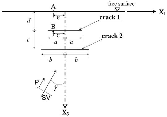
Figure 1 Elastic half-space that contains two near free surface parallel cracks excited by the incidence of P and SV waves.
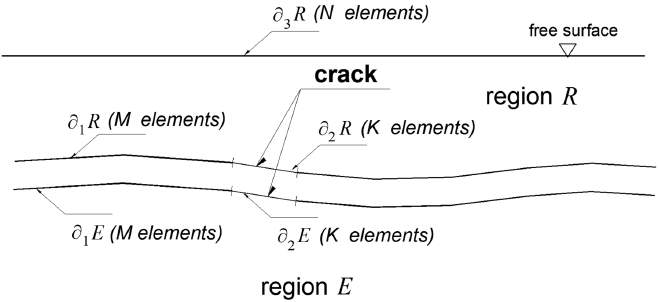
Figure 2 Configuration by regions R and E of the elastic half-space. The free surface is discretized in N elements, the crack in K elements, and the common interface among R and E in M elements.
Boundary conditions
According to Figure 2, the traction-free boundary condition is considered at the free surface (∂3 R), then this can be represented by writing:
On the other hand, the interface zone between region R and E exhibit continuity of displacements and tractions that can be established as:
Also, the tractions are null along the cracks and therefore we have:
and
Tractions and displacements on each region E and R can be estimated taking into account the contribution of the results in the free-field (results of the analytical solution of the half-space without cracks) adding the results of the diffracted field, then the equations (3) to (7) can be expressed as:
It is important to note that super-index 0 stands for the free field region, while super index d identifies the diffracted one. Now, using the integral representations of equations for displacements and (2) for tractions, the equations from (8) to (12) can be expressed as:
In order to solve numerically the system of integral equations constituted by equations (13) to (17), it is required to discretize them. It is assumed that ϕ i R,E (ξ) is constant in each element of the surfaces, which lead to a system of linear integral equations, where ϕ i R,E (ξ) are unknown. Then, the unknown ϕ i R,E (ξ) are obtained and used in the integral representation indicated by equations (1) and (2), and the complete displacement and traction values (in the diffracted and free fields) are determined at any point in the two-dimensional Euclidean space.
In the IBEM formulation, we take advantage of the multiregion concept. Therefore, the elastic space is divided into two media. From this criterion, a virtual boundary emerges, which represents the continuity of tractions and displacements between the regions R and E (see ∂ 1 R and ∂ 1 E in Figure 2). The other boundary corresponds to the crack face, for which, traction free boundary conditions must be imposed. The virtual boundary should be extended at least 2a from the crack tip, this approach usually guarantees good accuracy in the computations.
In this paper, we show essentially the influence of near free surface cracks on the diffracted wave field measured by receivers placed at the free surface. Special boundary elements may be used to model the singularity at the crack tip in order to retrieve fracture mechanics parameters; for example, the Stress Intensity Factor (SIF). However, it has been shown that radiated waves are insensitive to stress concentrations. As shown here, the use of constant elements has been enough for the studied frequencies. Our results at the free surface evince very good agreement with those obtained by Achenbach et al. (1983).
Numerical results
In this section, numerical results obtained with IBEM on various sets of cracks systems are exhibited. The analysis of elastic wave propagation in the intact, bi-crack and triple-crack models of Figures 1 and 2 are presented.
In this work, all the boundaries and interfaces are discretized into boundary elements. Three-hundred boundary elements are used for the validation case (K = 50, M = 100 and N = 150, for the maximum frequency calculated). For the extreme case of b/a=2, K = 100, M = 150 and N = 150 boundary elements are required. For all calculations, we consider 6-boundary elements per minimum wavelength and within each element Gaussian integration of 5 points is used. Section 3.1 reports the horizontal and vertical displacements changing with frequency for different crack configurations. In addition, Section 3.2 shows the wave propagation patterns in the mono-cracked and bi-cracked media by snapshots of the displacement field. Finally, Section 3.3 presents the synthetic seismograms associated with three-cracked media.
Results in frequency domain
The results obtained in this work were initially compared with those similar previously published by Achenbach et al. (1983) as presented in Figure 3. In this sense, the results correspond to a medium with a single crack excited by means of a P-wave with normal incidence. The elastic properties of the medium are: Poisson’s ratio v=0.3, S-wave velocity β=100m/sec, four different ratios (d/2a) of normalized depth d/2a =0.2 0.4, 0.6 and 1.0. For all cases, d is equal to the depth of crack 1 measured from the free surface and a=100m, stands for its length.
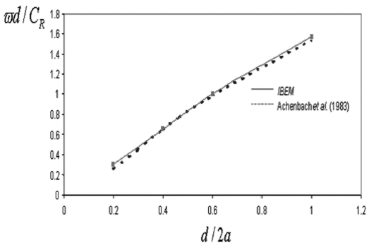
Figure 3 Curve that relates resonance frequency  d/CR and d/2a. Continuous line represents the results obtained by our method. Dashed line represents those obtained by Achenbach et al. (1983).
Figure 3 shows the dimensionless resonance frequencies  varying with ratio d/2a, where
  is the resonance frequency and C
R
represents the Rayleigh’s wave velocity. It is remarkable the good agreement between IBEM results with the results reported by Achenbach et al., (1983). As seen, the dimensionless frequency augments from about 0.3 to 1.6 as the normalized depth increases from 0.2 to 1.
Once the validation of our method was accomplished, several numerical examples were executed regarding a medium with two or more shallow parallel cracks subjected to P- or SV-waves incidence. Six case studies were considered to calculate both horizontal ∣u∣ and vertical ∣w∣ displacements at point A (see Figure 1, where e=0.75a) for vertical and oblique P-wave incidence with γ=0ºand γ=30º, respectively. Results presented in Figure 4a and b correspond to normal incidence of P-waves. These cases are related to ratios b/a=0, 0.25, 0.75, 1.00, 1.50 and 2.00 (crack 1 is placed at d/2a=0.2 and c=d). The case when b/a=0 means that the crack 2 does not exist.
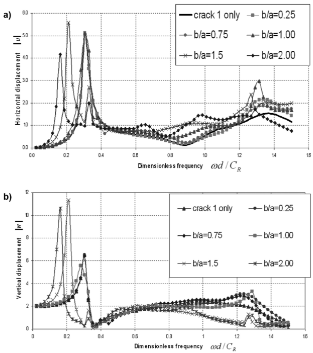
Figure 4 a) Horizontal displacements ∣u∣ at point A for six ratios b/a versus dimensionless frequency ωd/C R with vertical incidence of P waves. For the case of crack 1 only, the results can be expressed as the solution of Achenbach et al. (1983). b) Vertical displacements ∣w∣ at point A for six ratios b/a versus dimensionless frequency ωd/C R with vertical incidence of P waves.
In Figure 4a, the magnitude of horizontal displacements ∣u∣ at point A varying with the dimensionless frequency  are displayed. The maximum spectral amplitude of the single crack case, match very well with the spectral amplitudes of all ratios b/a ≤1.0, which contain 2 cracks. The interpretation of such behavior is: 1) the presence of the second crack, for all ratios below 1.0, does not affect the first resonance frequency and, 2) the equivalent layer placed between the free surface and crack 1, with the direct incidence of the P-wave generates a coupled displacement field at point A. Therefore, it is clear that the diffracted field generated by crack 2 does not create alterations of the displacement field at point A. This zero-effect is particularly characterized when the size of crack 2 is equal or lower than the length of crack 1 and γ=0º. In contrast, also in Figure 4a, we can see that for cases when b/a>1.0 the compressional wave propagation through the zone formed between the free surface and crack 2, generates maximum spectral amplitudes at lower dimensionless frequency in comparison with the case of a single crack. In other words, the presence of crack 2 (when it is bigger than crack 1) generates maximum spectral amplitudes of the system associated with lower frequencies.
It is important to remark that for both ratios, b/a=1.5 and b/a=2.0, the resonance peaks still appear at a dimensional frequency about  = 0.30, but with lower amplitude in comparison with those cases related to b/a≤1.0. One possible explanation of the generation of the second peak in the cases b/ a=1.5 and b/a=1.5 can be the local resonance in the region between crack 1 and the free surface. Likewise, Figure 4b presents a similar behavior and important amplifications of the vertical displacement field ∣w∣ occur for the cases b/a=1.5 and 2.0 at low frequencies. For the two particular cases of Figure 4, additional resonance peaks at non-dimensional frequency about 0.32 are observed. However, the group of resonance peaks are almost imperceptible at the free surface. It is noted that the relative size of crack 2 with respect to the crack 1 size controls the spectral amplification response.
For the homogeneous case, when an incident P wave propagates through intact media (non-cracked) along the normal direction towards the free surface, only vertical displacements are expected. Consequently, there is not any conversion from P to S waves. This means that ∣w∣=0 for all frequencies. Otherwise, when the incident compressional wave impacts the cracks, then horizontal displacements are generated (Figure 4a). The conversion of energy from P to S waves is present in the model. In fact, the particle motion determined at point A describes the horizontal component of the displacements caused by the eccentricity e (see Figure 1). It can be observed that there are non-zero amplitude values for all frequencies and for all b/a configurations.
In Figure 4b, a dip to zero of the vertical displacements is observed at a normalized frequency of about 0.35 (for all values of b/a). Among other wave characteristics, for example, creeping, crack-edge-effects or multiple-scattering, this displacement dropping could be attributed to two main facts: 1) there is a change of sign of the vertical displacement field relative to X3 axis. In other words, the displacement field computed at the free surface is affected by the change of polarization; and 2) it is exhibited that at the normalized frequency of about 0.35, a generalized significant decrement of the amplitudes is given by the interferences and interactions of the P wave travelling up and down in this model. This feature might be considered as a spectral signature of the specific cracked configuration.
The fundamental dimensionless frequency (associated with the first and maximum spectral amplitude) of the system that contains two cracks varying with the ratio b/a is depicted in Figure 5. Here, it is possible to see that for the ratios b/a≤1.0, the resonance frequency of the system is controlled by the equivalent layer between crack 1 and the free surface. This phenomenon is attributed to the relative high compliance exhibited by the single crack system in comparison with the response of the virtual layer formed between crack 2 and the free surface, including crack 1. When the ratio is b/a>1.0, the resonance frequency drops as b increases in comparison with a.
On the other hand, Figure 6 shows the variations of the absolute value of horizontal displacements calculated at points A and B of Figure 1 versus the dimensionless frequency. Three incidence angles of the P-wave are considered γ=0º, 30º and 60º, the displacements associated with each case are depicted in Figures 6(a), (b) and (c), respectively. It was taken a unique ratio b/a=1.0 for all the cases and points A and B were fixed at b=0.75a. Clearly in all cases, the absolute horizontal displacements at point A are higher than the displacements estimated at point B, this fact occurs independently of the angle of incidence. This effect can be interpreted as the maximum spectral ordinate given by the seismic response of the cracked system at the free surface. In addition, two conspicuous resonance peaks in the range 0.2≤  ≤0.4 at point B are identified. The first peak could be associated with the local amplification of the fundamental frequency of the cracked system, while the second peak might correspond to the characteristic frequency of the virtual layer placed between crack 1 and crack 2. The second peak might be generated by the stiffness and thickness of the layer between crack 2 and crack 1 and it is almost imperceptible at the free surface, even with the variation of the incident angle. Therefore, if crack 2 is smaller than crack 1, the presence of the second peak might not be detected.
Snapshots of displacements
In order to show similarities and differences of the total diffractions generated by a single crack and two-parallel crack models, snapshots of the vertical displacements ∣w∣ for five consecutive times are presented. We have studied the spatial distribution of amplitudes during a lapse of propagation time using meshes 400 x 240 m of evenly spaced receivers. The instant frames of time were obtained by convolution of a Ricker wavelet of t p =1s and λ c =a/2=50m of wavelength, followed by an inverse Fourier transform and then plotted as images. Snapshots are useful to understand by means of visualization, among other physical characteristics, the diffraction and polarization effects of the displacement field, particularly in time domain. In Figure 7 and 8, the snapshots that correspond to the single crack system are depicted in the left section of the figure, while the right portion covers the snapshots of the two-parallel crack system. In all cases, it is important to point out that the free surface is located at the bottom of each snapshot and the incident waves travel toward the free surface. The time increment between each correlative snapshots is 0.52 s. For simulations, a characteristic period of t p =1s has been selected for the Ricker’s incident pulse. Figure 7 shows normal P wave incidence exciting a medium with a single crack (left) and two cracks (right). For both cases, crack 1 is located at d/2a=0.2 while crack 2 is at c=d and a ratio of b/a=0.25 is considered. For times t=1.95 and 2.47 s, the incident pulse is clearly seen as a lighter and complete bar. In contrast, diffracted wave fields are observed for times from t=2.99 to 4.03 s. A strong diffraction in the interior of the medium is observed at t=3.51 s in the single crack model. Otherwise, a completely different scattering pattern is seen for the case of two cracks, where less number of diffracted waves are produced from the smaller crack. The presence of the shorter crack reduces the wave amplitude of the incident field before it impacts the nearest free surface crack. In this case, despite of single and multiple scattering patterns exhibited at t=3.51 s, the displacement field observed at the free surface for both cases result very comparable. Similarly, the wave propagation patterns observed in Figure 7 were also detected for the oblique incidence of P waves (γ=30º) depicted in Figure 8, in which the displacement fields at the free surface are also controlled by crack 1.
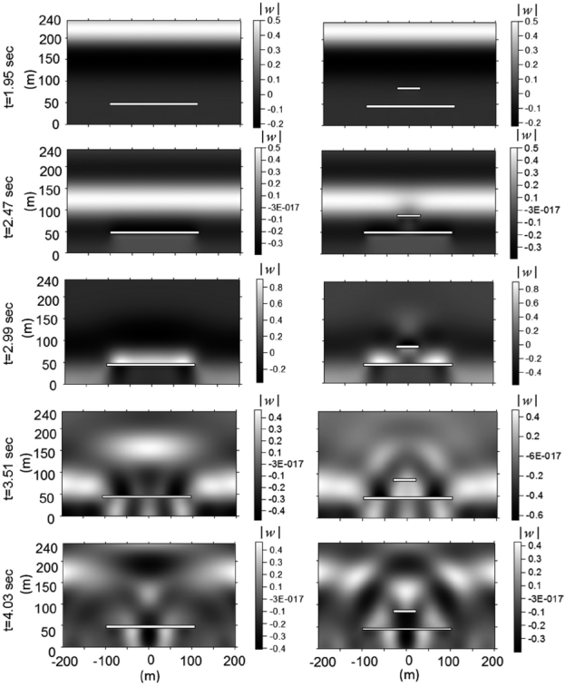
Figure 7 Snapshots representing the wave propagation phenomenon in a medium with cracks. Normalized vertical displacements for the case of a single crack (left) and two cracks (right) excited by a normal P wave incidence are depicted.
Synthetic seismograms and seismic response
Following the two configurations of the problem depicted in Figure 9, a Cartesian plane was defined through axis X1 (abscissas) and axis X3 (ordinates) with the origin located at the free surface. The reference plane is considered to compute synthetic traces by means of the Fourier´s transform. In the synthetic seismograms presented here, a Ricker wavelet with central frequency, ω
c
=1/, t
p
=1s, t
s
=3s s, s is used for all the examples. With the aim of avoiding aliasing effects, a quality factor Q= Q
E
=Q
R
Q=100 was maintained constant for both, P and SV waves. Such consideration permits the representation of hysteretic damping by using the factor (1-i/2Q) over the dimensionless frequency  in general, three parallel cracks are included in the media at different depths. Crack 1 is the shallowest at depth d, while depth between crack 1 and 2 is equal to c. The total length of crack 1 is 2a and crack 2 has a length of 2b. The third and deepest crack, has a length of 2g with a depth of d + c + f and ratio d/2g =0.6. The cracks are centered with respect to axis X3. Both, P and SV waves propagate towards the free surface with an angle of incidence γ. Finally, points A and B represent locations of interest for the numerical analyses at a distance e from X3. Point A is positioned at the free surface level and point B is at the same depth of crack 1.
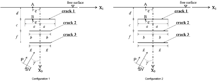
Figure 9 Two crack-model configurations that represent the elastic half-space containing three near free surface parallel cracks. The excitation is given by the incidence of P and SV waves. Configuration 1 shows three cracks with different lengths, while in configuration 2, three parallel cracks of same sizes are shown.
Figure 10 presents the synthetic seismograms for a case of three parallel cracks from the total displacement field for a row of surface receivers located horizontally ranging from X1 = - 300 m to X1 = 300 m. In all time histories, the total duration of the movement is t=8.4 s. The horizontal ∣u∣ (Figures 10a and 10b) and vertical ∣w∣ (Figures 10c and 10d) normalized components of displacement are shown for two different configurations for normal, γ=0º (left) and oblique, γ=30º (right) incidence of plane P waves. Figures 10a and c correspond to the model of crack 1 with length of a=100m and located at depth d/2a=0.2; while crack 2 has b=0.25 a with a depth c + d with d/2a=0.4 and c = d, and the third and deepest crack, has a length g = b with a depth d + c + f, with d/2g=0.6 and f = c = d (see Figure 9, Configuration 1). Moreover, configuration 2 is very similar to the first one, except that the deepest crack has a length d=100m. Time histories for this configuration can be seen in Figures 10b and 10d. The main difference between first and second configurations is that g=0.25a for the first one, and a = b = g =100m (three parallel cracks of same lengths) for the second.
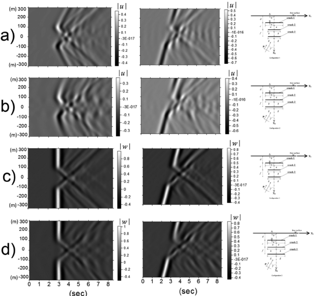
Figure 10 Synthetic seismograms of the displacement field for a line of surface receivers. Normalized horizontal displacements ∣u∣ are shown in a) and b), while vertical ones ∣w∣ in c) and d). The medium contains two different crack configurations, indicated at the right-hand side of the seismograms. The excitation is given by a normal (left) and oblique (right) P-wave incidence.
The purpose of this analysis is to illustrate how these two different model configurations produce very similar scattering patterns in terms of wave propagation. It is important to point out that basically the same displacement field is obtained at the free surface. Beyond analyses of the displacement field for both configurations and incidence angles, it is noted that both models exhibit very similar diffraction characteristics timewise. Inverse polarization patterns are clearly appreciated in the normalized horizontal ∣u∣ displacements for both configurations. A strong delay of 1 s on the original wave front can be directly measured from the seismograms, particularly in those of vertical components (see Figures 10a and d). It can be seen a slightly larger perturbation in the second configuration in comparison with the results of the first configuration, for both incidence angles. However, these small differences in the behavior, do not provide sufficient factual information to define the presence of a second or third crack. We strongly recommend that if relevant information is required about seismic characterization of heterogeneities or scattering from surface seismograms, a detailed study of coda should be performed. Otherwise, properties as attenuation or anisotropy could be omitted.
In order to analyze in detail the influence of shear waves on the three-crack system and their surface seismic response, in Figure 11 more analyses were executed for SV waves propagating with normal and oblique incidences, γ=0º and 30º, respectively. The results in Figure 11 are depicted in the same fashion as the previous case of incoming P waves (Figure 10). In general, the results obtained at the free surface for SV waves exhibit similar behavior compared with those observed for P waves. It is important to note in Figure 11, that the presence of a third crack does not give relevant information to identify its existence. Only a slight additional perturbation of SV waves for the three parallel cracks configuration and for both incidence angles is seen. These last set of results reinforce the previous partial interpretation; it is necessary to know and investigate the diffracted and scattered fields at the whole possible evaluation domains (a dense array of receivers and positions in time and frequency should be considered), otherwise, cracks behave like stronger reflectors of energy and their global effect can be poorly appreciated.
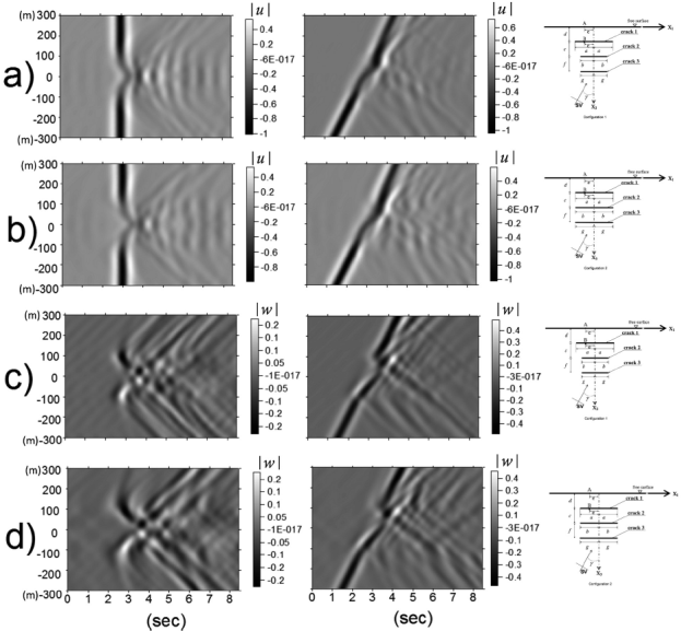
Figure 11 Synthetic seismograms of the displacement field for a line of surface receivers. Normalized horizontal displacements are shown in a) and b), while vertical ones ∣w∣ in c) and d). The medium contains two different crack configurations, indicated at the right-hand side of the seismograms. The excitation is given by a normal (left) and oblique (right) SV-wave incidence.
Concluding remarks
This article presents the application of the Indirect Boundary Element Method (IBEM) to calculate the response of a medium that contains a single, two or three near-free-surface-parallel cracks under the incidence of P and SV waves. The formulation presented here permits to treat the generated displacement fields by several interacting cracks with good efficiency. This numerical technique, which is based on an integral representation of the diffracted wave field, can be seen as a numerical accomplishment of the Huygens´ principle, since the diffracted waves are constructed at the boundaries and the cracks from where they are radiated. In order to validate the applicability of the IBEM to the problem of the propagation of elastic waves in cracked media, IBEM results reproduce very well those reported by Achenbach et al. (1983) for the case of a single near free surface parallel crack.
We studied six cases in the frequency domain and the impact in terms of scattering by the presence of one or two cracks was analyzed. A ratio b/a=0 (see Figure 1) means that crack 2 is not present and only one single crack is considered. In those cases, the horizontal displacements varying with frequency were compared with similar results obtained by Achenbach et al. (1983) and an excellent match was found. In addition, for ratios ranging 0<b/a≤1.0, the resonance peaks were controlled by the equivalent layer placed between crack 1 and the free surface and, vertical and horizontal displacements at point A were strongly affected at those resonance frequencies. However, when b/a>1.0 the resonance peak was dominated by the layer between crack 2 and the free surface. An extra resonance high frequency was detected which corresponds to a local resonant frequency of the virtual layer between crack 1 and the free surface (see Figure 4).
In all these cases, we have found that there are important difficulties to identify, in the frequency domain, the presence of a second crack located near to a free surface. This fact will be controlled by the characteristic excitation frequency range of the cracked medium and by the length of the second crack (see Figure 4). Moreover, for the particular case where crack 2 has a length of b/a=0.25, a time analysis was executed. It was observed that for both normal and oblique incidence of P waves, similar scattering patterns at the free surface are exhibited for the cases of single or two-near free surface parallel cracks. This observed feature leads to conclude that to identify the scattering effect caused by the presence of a second crack measured at the free surface in time domain, a detailed study of the multiple diffracted field by means of coda analysis or some amplitude decay methodology would be necessary; otherwise, important wave propagation phenomena as attenuation or anisotropy could be omitted.
Finally, two configurations containing three cracks excited by P and SV waves were analyzed. The results found also serious difficulties to extract information to identify the influence of the scattered field coming from the multiple patterns of the system. In fact, this set of results reinforce our interpretation that it is necessary to understand the diffracted and scattered fields generated in the whole model using results in both, frequency and time domains. In spite of this, cracks behave like stronger reflectors of energy and their global effect can be poorly appreciated and even more, as generally occurs in seismic studies, where measurements are only possible at the free surface.


 nueva página del texto (beta)


