1.Introduction
The study of aqueous foams is of great interest for the scientific community as it is of utility in several industrial processes, for instance, food, pharmaceutical, and manufacture industries. Oil industry mainly employs foam in the enhanced recovery of oil, and gas from naturally fractured reservoirs (NFR) 1,2.
The behavior and physical features of foams have attracted attention of the research community for long. Plateau3 since 1873 gave a first scientific description of foams. Foam is a bubble agglomeration; these bubbles are separated by thin liquid layers which commonly are called “lamellas". The mean features of a foam are: its relatively low density and high viscosity 4. Another important parameter is the foam structure, which is determined by the use of the foam generation method, and mainly by the shape and size of bubbles and its liquid retention capability. A foam has two phases, gas and liquid, the gas is compressible, thus, the foam is compressible too 1-4.
Because of the foam flow has a preference for paths with high permeability, in heterogeneous media, such as porous media or fractured media, in a first instance the foam is conducted to those zones in order to fill the available spaces and to avoid the pass of other injected fluids, deflecting them to zones with lower permeability, where the scanning efficiency increases 5,6.
There are some studies which give an explanation of the foam flow behavior through homogeneous single fractures7-9. Foam could be taken as an homogeneous medium and it is believed that it behaves as a no-Newtonian fluid. There are some complications in the foam rheology because when the pressure changes, its quality (volumetric fraction) changes too. In this sense, to make a rheological model it is necessary to know more characteristics of the foams like the mean bubble size and its size distribution 1,2. When the foam is contained in a recipient with larger dimensions than the mean bubble, we consider that the foam is in “bulk”4.
It is argued that the apparent viscosity of the foam is the sum of the liquid contributions between the bubbles and the resistance to deformation of the bubble interfaces passing through the fracture 7-9. The increase of the apparent viscosity with the fractional flow of gas is larger in thicker fractures (to certain bubble sizes). Due to this, the foam can deflect the flow from the thicker fracture to the thinner fracture 8-10. Commonly, works regarding foam flow in fractures are focused on the study of the fracture size effect on the apparent viscosity of the foam 10-12. To our knowledge, studies about foam flow behavior when it is simultaneously diverted into several transversal channels with different aperture sizes have not been reported yet.
Such a flow obeys the conditions postulated in the Poiseuille’s law, these are: an incompressible newtonian flow, occurring at a low Reynolds number, through a distance that is substantially longer than its diameter. Typically, in the Poiseuille flow, and consequently in the description of the capillary penetration, when the cross-section of the tube is not circular, the inner radius is substituted with an ad hoc hydraulic radius that takes into account the geometry of the channel 13,14.
Actually, the penetration in transversal channels takes place, for instance, in fractured systems where it is possible that a big fracture intersects other smaller ones. Or in foam extrusion to manufacture physically foamed plastic sheets, among others. Other examples of this phenomenon appear when the supply of water is limited or when drilling through cavernous formations, as in oil reservoir perforation, where the drilling mud flow is lost. It is encouraged to drill and to simultaneously inject an aqueous foam in those areas 15-17. Compared to other drilling fluids, foam muds have many advantages. This technique has been successfully applied into the drilling of depleted reservoirs around worldwide 18. In many cases, drilling assisted with foam has shown to provide significant benefits, including an increase in productivity, an increase in drilling rate, reduction in operational difficulties associated with drilling at low pressure reservoirs, and improved formation evaluation while drilling.
To understand how a foam flow is diverted this work is organized as follows: in the next section a series of experiments will be described. Then, in Sec. 3, we formulate the Poiseuille flow for straight channels rectangular cross-sections in a dimensionless form, which allowed us to define the friction factor, α, to compute the linear relation between a and the compactness C and the dependence of l on 𝛼(𝐶). In Sec. 4, we show the plots with the most important results of our analysis, and finally in Sec. 5 we give some conclusions of the results and the comparison with our analyzes.
2.Experiments
In order to perform the foam flow experiments in different transverse channels, an acrylic horizontal cell with five channels was built; each channel has a different aperture (see the scheme in Fig. 1). The transparent cell is hermetic and the unique apertures to the atmosphere are the indicated drills. This array of channels mimics a set of horizontal and parallel fractures transversal to a larger main fracture. Each fracture or channel has a given size to investigate how the diversion of the foam flow and the pressure gradients affect each channel. The foam injection method consists in producing foam under controlled conditions in a foam tank to maintain control on the formation pressure. Also, the control of the bubble size is enhanced 15,16,19. Finally, this foam is injected into the cell.
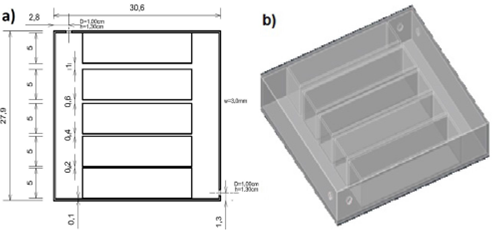
FIGURE 1 Scheme of the cell with transverse channels: (a) top view of an acrylic cell having five channels with different apertures, (b) lateral view of the cell showing the holes for foam injection and air relief.
The main channel has a 5 cm height, and a 27.9 cm length. It connects with five channel separated 5 cm each (to prevent the interaction between foam flowing to the apertures). Channel dimensions are 20 cm long and 5 cm hight. It has five channels of 1, 2, 4, 6 and 10 mm apertures, respectively.
The aqueous foam was prepared with a mixture of bi-distilled water and surfactant (commercial liquid soap) with a proportion of 30% weight of the latter, per each litter of bi-distilled water. The mixture was made and contained in a pressurized tank, 49 liters in volume. The aqueous foam was made by using a compressor that injected air at 689.47 kPa to the tank. The aqueous foam tank had a valve at the top through which the preformed foam was conducted to the experimental cell. The injection pressure of the foam in the cell was controlled and measured by a pressure transducer just before the cell inlet. The entry of aqueous foam into the cell was video recorded at a 30 fps rate. With the sequence of digital images from the video, the respective bubble size and motion of the front of foam, in each channel, were obtained (see Fig. 2). A more detailed visualization of the aqueous foam sizes was also performed by using a digital microscope with a 16Xzoom for the determination of bubble sizes in each channel.
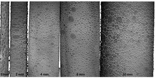
FIGURE 2 Bubbles in each channel. The bubble population had a mean size which yields that in the channel size. The channel size is shown in the lower part as well. This scale serves to identify the size of the bubbles.
There are two scenarios during the foam injection. In the first one, the injected foam interacts immediately with the channels of narrow opening. In the second scenario, the foam interacts first with those presenting a wide opening. As a result of this difference, the speed of the foam front obeys an interesting dynamics for different values of the pressure injection. It is important to note that a relief hole was kept open during the foam injection to avoid compression of air in the cell and to maintain the pressure at its opposite side at the atmospheric pressure value
Pictures in Fig. 3 show that the aqueous foam advances at different velocities, depending on the channel aperture. The time of arrival of the foam to a given channel is different due to its separation to the injection orifice.
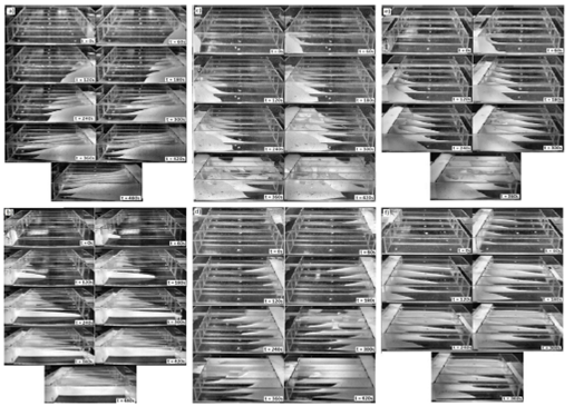
FIGURE 3 Snapshots of foam diversion into channels of different apertures and three different injection pressures Pi = 84269 N/m2, Pi = 82200 N/m2 and Pi = 80821 N/m2. The foam (white or gray soft zones) advances at different speeds, depending on the cannel aperture. The time of arrival of foam to a given channel is different due to its separation to the orifice injection. The injection starts close to the channel of smaller opening as shown in pictures a), c) and e). In other cases, the injection starts close to the channel of bigger opening as shown in pictures b), d) and f).
3. Friction in channels
The objective of this work is to present an argument to model the foam penetration into simple channels of different openings. The main hypothesis in our treatment is that a Poiseuille flow occurs in horizontal channels in which the Reynolds number is low. Under these circumstances it is possible to introduce the dimensionless hydraulic resistance as 13,14.
By definition, the hydraulic resistances
where is the pressure drop of the foam flow along the channel, Q is the volume flow rate of foam in the channel, L is the distance penetrated by the aqueous foam and A is the cross-sectional area of the channel
Due to the flow in the channel obeys a Poiseuille flow whose velocity is
where
so, the solution of Eq. (7) allows us to give the hydraulic resistance in the form
Using the non dimensional variables
and the Poiseuille Eq. (7) is transformed in
whence, the friction factor is
If the channel has a rectangular cross-section of height 2w and width 2h with w ≠ h,, the aspect ratio is
Macroscopically, the Poiseuille law can describe the flow in a channel at low Reynolds numbers and when the medium is filled by a Newtonian fluid. In this law, the speed of the flow is directly proportional to the pressure gradient
where b, is the channel aperture, where the information is already included in the channel aperture, thus the pressure gradient has the form,
where l is the channel length. With experimental data and previous equations we can find out other important parameters for understanding the behavior of foams channels. In this way, the apparent viscosity value can be obtained from the experiments, which are shown in the next section.
4. Results
The effect caused by the channel aperture on the bubble size induces important phenomena which were observed in all the experiments performed. For instance, the pre generated foam has a uniform mean size
The foam fronts as a function of time, in all channels, were obtained and plotted in Fig. 5. It is observed that in the channels with a narrow aperture the foam speed is low, and the opposite is observed for the wide channels. Three different injection pressures were used in the experiments. In Fig. 6 the speed of such fronts is plotted. This behavior of the foam is important because it allows us to corroborate that there is a high resistance to the foam flow in channels with narrower apertures, implying that there is a stronger shear stress, a very high effective viscosity and a coefficient of friction. Plots on the left side correspond to cases where foam first interacts with the narrow aperture channels and plots on the right side show cases where foam first interacts with the wide channels.
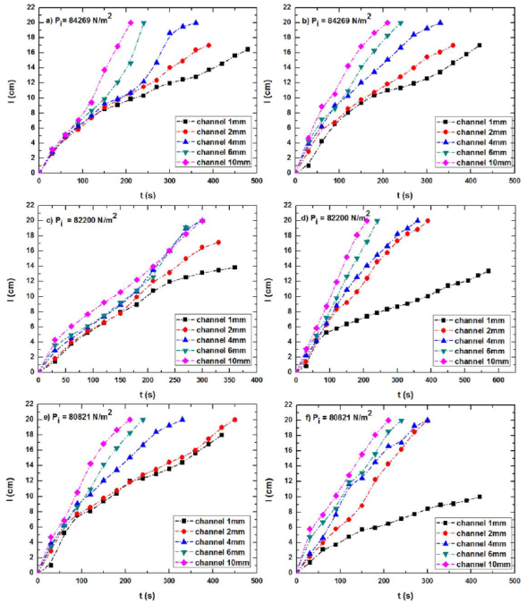
FIGURE 5 Plots showing the position of advance fronts of the foam, l, in the channels of different apertures as a function of time, t. Plots on the left side correspond to cases where foam first interacts with the smaller aperture channels and plots on the right side show cases where foam first interacts with the wider channels. In the experiments, three different injection pressures were used.
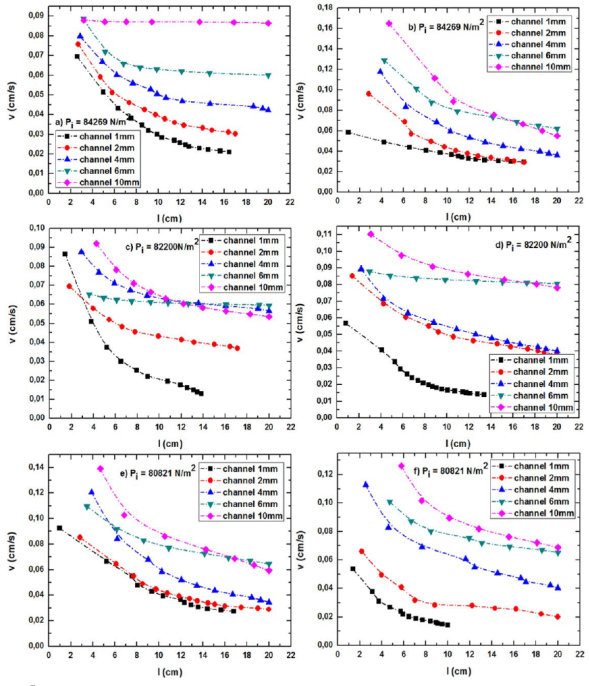
FIGURE 6 Plots showing the foam speed in the channels of different apertures, v, as a function of advance fronts of the foam, l. On thev left side, foam first interacts with the thinnest channels and plots on the right side correspond to cases where foam first interacts with biggervchannels.
Analyzing the plots of Fig. 5, it is clearly observed that the foam advance is slower if the channels are narrower. However, as an aperture channel overcomes the capillarity length, (
On the other hand, the most important parameter affecting the foam viscosity is the foam texture. Fine-textured foams have more lamellae per unit length and as a result, a greater resistance to flow is obtained 2,4,5. No bubbles aggregation or coalescence were observed in the studied region.
Another important point is that the number of lamellas per unit length or per unit area increases by decreasing the bubble size and increasing in the flow. As a result, the apparent viscosity and friction factor would be significantly higher either for narrow and wide channels than the opening of thicker bubbles, particularly in the relation
The same was done for two more cases where only the injection pressure was changed. In the plots shown above, three characteristic behaviors of fluid flow in open channels can be observed. In the channel of lower aperture (1 mm) it is observed that in some cases, the capillary forces dominate the foam behavior. The capillary pressure existing in this case is large enough to be dominant, the apparent viscosity also plays a role in the flow behavior and gravitational forces as well. In intermediate aperture channels (2, 4, and 6 mm) a different behavior is observed, in which viscous forces are dominant in the foam performance when interacting with the channels. Mainly in the channel 2 mm, an oscillation between the viscous and capillary forces is observed. In 4 and 6 mm width channels, oscillations are observed in the behavior of the foam, due to the effects of the viscous and gravitational forces. In the 10 mm channel there is a greater volume of foam causing the body effects to be greater, since the effects of gravity are greater due to the volume of foam in the channel.
5.Conclusions
Simultaneously injecting foam into channels of different openings is a way to understand the interaction of foam with different geometries. Channel openings (fractures) have an important effect on foam flows, ensuring a barrier on narrow opening fractures. However, the flow is also affected by the size of the foam bubbles which in turn is affected by the channel openings as a strong co-dependence between the channel aperture and the bubble size, which is quantified in the apparent viscosity. Open channels have a significant effect due to gravity


 nueva página del texto (beta)


