1 Introduction
The theory of scattering of a monochromatic electromagnetic plane wave from a sphere goes back to the first decade of the 20th century [1] . Subsequently, A. L. Aden and M. Kerker [2] found the first analytical solution for the scattering of an electromagnetic wave from a core/shell particle with spherical symmetry. Y. Nomura and K. Takuka obtained the rigorous solution of Maxwell’s equations in an inhomogeneous medium, which led to description of the electromagnetic waves propagation across the atmosphere, it is treated like many layers of concentric spheres [3]. C. T. Tai presented a general discussion of the electromagnetic field involved in a radially stratified medium [4]. Generalization of the problem of the scattering of an electromagnetic wave from a spherical core/shell particle was done for any number of concentric homogeneous regions [5].
One of the first computational studies to analyze the optical properties of core/shell particles was made by R. W. Fenn and H. Oser [6]. The first quantitative study comparing numerical and experimental results of scattered light by dielectric spheres coated by a spherical shell of a second material (silver chloride-core/linolenic acid (C18H32O2)-shell), was performed by W. F. Espenscheid et al. [7]. A summary of the scattering theory and some practical applications was developed by M. Kerker [8]. However, computational errors were found to evaluate the Bessel functions [7,8,9,10], which appear in the work developed by M. Kerker et al. [11]. The code advance solved those errors and the numerical study of the interaction between core/shell particles with electromagnetic waves has been more accurate [12,13,14,15]. Currently, BHCOAT [12] is one the most used algorithms to calculate the absorption, extinction and scattering cross section of a core/shell particle. Since then, different researches have been studying, with this code, the interaction between an electromagnetic wave and core/shell particles, especially those which the core is a dielectric and shell is a metal (also named as nanoshell [16]) [17,18,19]. e.g., N. Harris et al. demonstrated that the geometry of gold nanoshells causes a maximum surface heat flux [17].
One of the highly analyzed aspects is the excitation of localized surface plasmons resonances (LSPR) at core/shell particles. Studies have shown that LSPR can be tuned in a wide range of the electromagnetic spectrum by varying the shell thicknesses [16,20,21,22]. Z. Wang et al. studied theoretically the optical absorption of carbon-core/gold-shell particles with spherical and cubic geometry, focusing on the influence of the shell on the intensity and width of the absorption spectrum [23]. Others studies have shown that there is an increase of the intensity of the absorption spectrum of core/shell particles compared to pure metal particles [24,25]. One of the most studied metals in core/shell type nanostructures has been gold combined with a dielectric. Those studies have explained the shift of the absorption band as a function of the relationship between the inner and outer radii of the particle. Studies on the absorption of Au2S-core/Au-shell have also be done. H. S. Zhou et al. attributed that this shift of position of the LSPR is determined by the quantum confinement of electrons on shell [19]. On the other hand, R. D. Averitt et al. [22] attributed it to purely classical behavior that is determined by dimensions and the properties of the core (Au2S) and the shell (Au), i.e., classical electrodynamics effects, e.g., dependence of the real part of dielectric function (
To the best of our knowledge, there is no report on the calculation of the analytical solution of resonance frequencies in the quasi-static limit as presented in the Eq. (13), for a dielectric-core-/metal-shell and neither a comparison with electrodynamic calculations. Thus, a comparison between the positions of the resonance frequencies of a vacuum-core/Drude-shell particle surrounded by vacuum with both approaches was done. On the other hand, we calculated the distribution of the near electric field from gold-core/silver-shell nanoparticle at fixed wavelength of incident electromagnetic field and we found some differences compared to those reported in the Ref. [31].
2 Theory
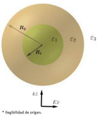
In this paper, we consider a core/shell nanoparticle (see Fig. 1), with spherical symmetry, in the presence of an incident monochromatic electromagnetic plane wave with the direction of propagation on the positive Z-axis and a polarization of the electric field along the X-axis. The electromagnetic fields are expressed in their multipolar expansion as follows [33,34]:
where m = 1,2,3 indicates the core, shell and embedded medium, respectively, qm is the wave number of the medium,

Figure 1 Representation of core/shell particle comprised for two different materials, with R1 and R2 the inner and outer radii.
An extension of Mie’s theory can be used to calculate the near electric field distribution as well scattering cross section
where
3 Numerical results
Two different core/shell particles were studied numerically. The first were gold-core/silver-shell nanoparticles and its inverse configuration embedded in vacuum or water. The second particles were vacuum-core/Drude-shell surrounded of vacuum, symmetric configurations. The values of dielectric functions for gold and silver correspond to the bulk metals [35], which were interpolated, and they were calculated to the same wavelength for both metals. We compute the square module of the electric field as a function of r (r > 0, R1 < r < R2 and r > R2) for a fixed wavelength.
All calculations of scattering cross section (
3.1 Gold-core/silver-shell and silver-core/gold-shell nanoparticles
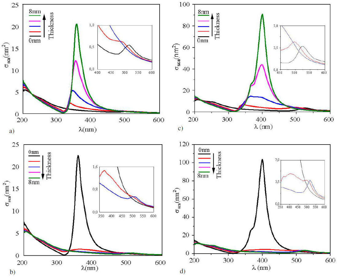
In Fig. 2,
Table I Resonance positions as a function of thickness for metallic core/shell nanoparticles.
| Thickness (nm) | LSPR positions (nm) in vacuum | |||
|---|---|---|---|---|
| gold-core/silver-shell | silver-core/gold-shell | |||
| 0 | 517 | ND* | 357 | ND* |
| 2 | 494 | 336 | 364 | 494 |
| 4 | 379 | 345 | 368 | 502 |
| 6 | 375 | 354 | ND* | 515 |
| 8 | ND* | 357 | ND* | 517 |
| Thickness (nm) | LSPR positions (nm) in water | |||
| gold-core/silver-shell | silver-core/gold-shell | |||
| 0 | 525 | ND* | 365; 400 | ND* |
| 2 | 496 | 336 | 365; 404 | 496 |
| 4 | 488 | 365; 395 | 365; 406 | 517 |
| 6 | ND* | 365; 398 | ND* | 521 |
| 8 | ND* | 365; 400 | ND* | 525 |
ND*: None Defined

Figure 2 Scattering cross section as a function of the wavelength for core/shell nanoparticles, the outer radius was fixed at 10 nm. a) and c) gold-core/silver-shell, thickness from bottom-up. b) and d) silver-core/gold-shell, thickness from top- bottom. a) And c) surrounded by vacuum, b) and d) surrounded by water (n = 1.33). The thicknesses d of the shell was of 0, 2, 4, 6 and 8 nm, respectively, in all figures. Insets show resonances amplification for configurations with thickness of 0, 2 and 4 nm, respectively.

Figure 3 a) Projection on the Z - X plane of the square module of electric field at 354 nm (resonance in Fig. 2a) near to core/shell particle, b) at 387 nm and c) at 620 nm, out resonance. The white circles represent the limits between the different materials: core/shell and shell/embedded medium. Values of wavelengths were taken from scattering cross section of a gold-core (4 nm)/silver-shell (6 nm) nanoparticle, magenta line in Fig. 2a).
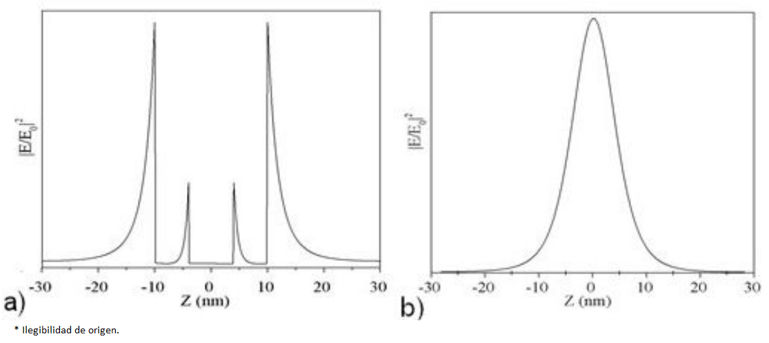
The distribution of near electric field (NEF), i.e., the square module of electric field, for a fixed wavelength is shown in Fig. 3. The spatial distribution of NEF was possible due to compute of all coefficients of electromagnetic fields in the core, shell and embedded medium. The Fig. 3 shows that the square module of electric field is maximum near to outer shell and core surfaces, as shown in Fig. 4a). In fact, this is very interesting because the field decays sharply inside the shell and core surfaces.

Figure 4 Projection along Z-axe of the square module of electric field. a) For X=0 and b) for X=10 nm. We take this projection from Fig. 3a).
However, in the direction of polarization of the electric field, i.e., X-axes, the maximum value on the core surface (63.14) is only three units less compared with the maximum value on the shell surface (66.4) -the values inside the parenthesis were taken from the data in Fig. 3a). In this sense, the NEF intensity generated on the gold core surface (4 nm radius), as consequence of the decay (in the direction of the polarization of the electric field) inside of the shell is almost three times greater than the intensity (19.5) generated by a gold sphere (see Table II). One clear evidence of the fact that the maximum value of the near field intensity is maximum in the direction of polarization of the electric field can be seen in the Fig. 4b). In this sense, our results disagree with those reported by C. Zhang et al. [31]. e.g., Figs. 4a), 4c), 10b, 10d, show that the near electric field value is not maximum on outer metal shell surfaces and, this cannot be possible.
Table II Maximum value of
| Au shell thickness (nm) |
λ (nm) of maximum in |
|
|---|---|---|
| 0.0 | 357 | 124.0 |
| 0.2 | 358 | 67.60 |
| 0.5 | 360 | 39.40 |
| 1.0 | 362 | 24.10 |
| 1.5 | 363 | 18.05 |
| 2.0 | 363 | 14.95 |
| 10.0* | 517 | 19.15 |
*This value corresponds to a gold sphere with 10 nm radius.
Our results suggest that the calculations developed by C. Zhang et al. may underestimate the coefficients in the core and shell for the fields -the asymmetric distribution of the near electric field around the center of the particle in Figs. 3c), 3d); black holes in Figs. 3b), 10d) could validate our appreciation. Furthermore, the NEF value for the same configuration cannot be equal for a resonance wavelength in the cross sections and another out of resonance, as shown in Ref. [31]. In addition to these features of the NEF, our data also exhibit that it decays approximately as
On the other hand, the intensity of near electric field is proportional to the scattering cross section intensity, as shown in Fig. 3, and this agrees with the reported by B.J. Messinger et al. [29] e.g., at resonance wavelength (354 nm) (Fig. 3a)), the near electric field intensity is about five times larger than out of resonance (620 nm) (Fig.3c)). The incident electromagnetic wave causes an enhancement on shell surface, but not on the core surface, as shown in Fig. 3c).
Table II shows the maximum value of the NEF intensity for gold thickness from 0 to 2 nm, keeping the silver core radius fixed at 10 nm. The quantum confinement was not considered. This was done to determine how much the intensity of the fields varied for small shell thicknesses. The maximum value of
In summary, gold-core/silver-shell nanoparticles present more variation of the optical properties. It is possible to have a control over the intensity as well the resonance wavelength position. This control could be very helpful for applications in efficiency from Raman activity [39,40], energy transfer to the adsorbed species to enhance the photo-catalytic process [41] and fluorescent molecules located on or near to surface of noble metals [42,43]. The maximum value of the square module of the electric field is located on the outer metal surfaces in the direction of the incident electric field and its spatial distribution is like that of an electric dipole.
4 Resonance frequencies in quasi-static limit for a vacuum-core/Drude-shell particle surrounded by vacuum
When the magnitude of wave vector
The coefficients a l and b l are found by using boundary conditions of electric potential, Eq. (5), and the orthogonally properties of Legendre Polynomial’s. The boundary conditions are:
where
where
The resonance conditions for the potential in the Eq. (8) are given when the denominator q(+) (Eq. (10)) has its minimum value, i.e., it is zero. Our interest is focused in the case when the core and embedded medium is the vacuum, i.e.,
where
where
For f = 0:
For f = 1:
It is well known that for

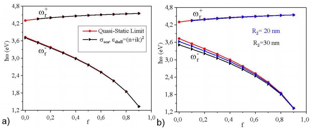
Figure 5 The resonance frequencies as a function of the filling ratio. a): Comparison between the positions of resonance frequencies obtained with the quasi-static limit (Eq. (13)) -circles on the red lines- and ones calculated with electrodynamic (Eq. (3))-triangles to the right on the black lines- for vacuum-core/silver-shell nanoparticles as a function of f for R2 = 10 nm fixed. b): triangles to the right on the blue and black lines are the resonance frequencies predicted from electrodynamic theory, for R2 = 20, 30 nm, respectively.
The results given for the electrodynamic theory are in good agreement with predicted by quasi-static limit as shown in Fig. 5a), i.e., when the dielectric function keeping the damping constant
In this case, the positions of the resonance frequencies predicted by Eq. (13) have higher values that given for Eq. (3) for all values of f with a maximum error of 0.66% between both theories when f = 0. For f = 1 both theories give the same results,
5 Conclusions
A study of the diffraction of a monochromatic electromagnetic plane wave from a core/shell particle was presented. It was demonstrated that for metallic core/shell configurations the interference of electric field produced on core/shell surfaces modified the scattering cross section in comparison with one sphere of core and shell material, respectively. The gold-core/silver-shell nanoparticles are those that present more variation of the optical properties, and it is possible to have a control over the intensity as well as the resonance wavelength position. When the metallic core/shell nanoparticle is surrounded by a medium with higher refractive index (water) the resonance positions shift to higher wavelengths in comparison with vacuum. We have shown that electrons in the two interfacial zones respond to an external field generating an enhancement of the near field on the outer metal surfaces and, its maximum value is located on the direction of polarization of the incident electric field. Furthermore, it decays approximately as


 nueva página del texto (beta)


