1 Introduction
The radiation produced by an electric dipole near a planar interface has been well studied over the years and has remained a relevant subject of research for physicists and engineers due its relevance in a wide range of phenomena like practical applications in radio communications [1], THz Zenneck wave propagation [2], near-field optics [3], plasmonics [4] and nanophotonics [5], just to mention a few examples. In 1909, Sommerfeld [6] published a theory for a radiating vertically oriented dipole above a planar and lossy ground which formed the basis for subsequent investigations [7,8,9,10,11]. Probably, by the fact that the early theory of dipole emission near planar interfaces was written in German, although there was an English version summarized in Sommerfeld’s lectures on theoretical physics [12], many aspects of the theory were reinvented and clarified over the years [13,14,15,16].
Here we consider planar interfaces constructed with linear homogeneous and isotropic magnetoelectric (ME) media giving rise to the so called magnetoelectric effect (MEE), whereby electric (magnetic) fields are able to induce additional magnetization (polarization) in the material. This effect, which was predicted [17] and discovered [18] in antiferromagnets, has been widely studied along the years in multiferroic materials and it is codified in an additional parameter of the material: the magnetoelectric polarizability (MEP) [19]. The recent discovery of three-dimensional topological insulators (TIs) has boosted the interest in this topic by providing new materials where this effect is predicted to occur [20,21,22,23,24,25]. Generally speaking, TIs belong to a novel state of matter in which the characterization of their quantum states does not fit into the standard paradigm of condensed matter physics whereby the phases of the material are classified according to order parameters arising from the spontaneous symmetry breaking of the corresponding Hamiltonian according to the phenomenological Ginzburg-Landau theory. A distinguished example of this classification are normal superconductors, where gauge invariance is spontaneously broken. Instead, these states are classified according to topological invariants that arise in the Hilbert space generated by the corresponding Hamiltonians in the reciprocal space of the crystal lattice. They are protected by time-reversal-symmetry (TRS) and admit an insulating bulk together with conducting surface (edge) states. The imposition of this symmetry yields two classes of materials: standard insulators labeled by a zero MEP and TIs characterized by a MEP equal to π. These new materials host a number of exceptional electromagnetic properties. Among them we have: (i) they can carry currents along the edge channels without dissipation, (ii) their MEP is quantized, (iii) the conducting edge states can be interpreted as quasi-particles being massless Dirac fermions. This by itself is an important feature that makes contact with high energy physics and which provides the opportunity to investigate the existence of unseen particles like Majorana fermions, for example. (iv) they are predicted to exhibit the quantized photogalvanic effect in which light can induce a quantized current. For an extensive review of the properties of TIs see for example [26,27,28]. All these new features provide additional motivation to reconsider the problem of radiation in magnetolectric media.
The effective theoretical framework to deal with magnetoelectric media is motivated by axion electrodynamics [29], which consists of adding the term
The paper is organized as follows. In Sec. 2, we present a review of ϑ-ED which also contains a summary of the calculation of the time-dependent Green’s function (GF) for the 4-potential Aμ in our setup. As the source of the electromagnetic fields, in Sec. 3 we introduce an oscillating vertically oriented point-like electric dipole located at a distance z0 > 0, on the z-axis perpendicular to the interface between the two media. The convolution of this source with the GF is carried out in the Subsec. 3.1 and yields the corresponding electromagnetic potentials
This approximation,which heavily relies upon Ref. [13] is explained in detail and carefully carried out in the Appendix B. These results are summarized in the Subsec. 3.1.
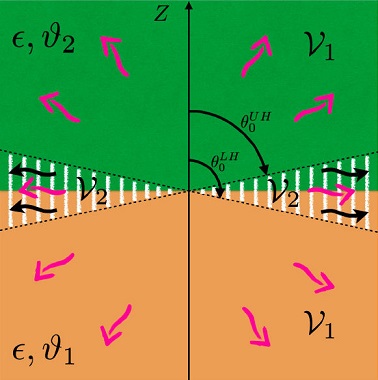
As a consequence of the presence of the pole we find that the 4-potential acquires a contribution from axially symmetric cylindrical waves (denoted also as surface waves) besides the standard spherically symmetric ones. A detailed analysis on the former kind of waves allows us to introduce what we call the discarding angle θ0, which permits us to divide the space in two regions:
2 ϑ-Electrodynamics
Let us consider two semi-infinite ϑ-media separated by a planar interface located at z = 0, filling the regions
where
which require to specify additional constitutive relations characterizing the medium under consideration. In the case of the magnetoelectric media the constitutive relations are
Here α is the fine-structure constant,
where
In the case of a TI located in the region
The homogeneous Maxwell equations still enable us to define the electromagnetic fields E and B in terms the electromagnetic potentials Φ and A as
We observe that Eqs. (4) and (5), together with the constitutive relations (3), can also be derived from the action
which clearly incorporates the modified axion term
The Eqs. (4) and (5) explicitly show that there are no modifications to the dynamics in the bulk (z ≠ 0) with respect to standard electrodynamics. Nevertheless, as it is well known, the solution of a system of differential equations depends crucially upon de boundary conditions. In this way, the new physics induced by
Assuming that the time derivatives of the fields are finite in the vicinity of the surface z = 0, the modified Maxwell equations (4) and (5) imply the following boundary conditions (BCs)
for vanishing external sources on the surface z = 0. The notation is
A convenient way to deal with the fields produced by arbitrary sources in electrodynamics, in particular in ϑ-ED, is by using the corresponding GF
In what follows we restrict ourselves to contributions of free sources
which satisfies the equation
in the modified Lorenz gauge
The detailed calculation of the GF is reported in Sec. 3 of Ref. [42]. Here we only recall the results that are written in terms of
The final result is presented as the sum of three terms,
Here
3 Electric Dipole perpendicular to the interface
In this section we determine the electric field of an oscillating point-like electric dipole
3.1 The Electromagnetic Potential Aμ
The charge and current density for this dipole are
respectively, where
where
The derivation of the above results can be found in the Appendix A.
The next step is to calculate the integrals (19)-(21) in the far-field approximation. To begin with, we recap the main ingredients of the calculation carried out in full detail for the function
where erfc(z) denotes the complementary error function. The contributions in curly brackets arise from the terms including the subtracted pole, they are are well behaved at
On the other hand, the terms from the erfc function in square brackets arise from the pole itself and describe wave propagation corresponding to the amplitude
The crucial point is that the amplitude of the cylindrical waves is modulated by the erfc function, with argument
which will provide us with a quantitative way of appraising the relevance of the cylindrical waves. To this end, we now discuss the behavior of the function
that we rewrite in terms of the the Faddeeva plasma dispersion function
which controls the amplitude of the electromagnetic fields of the cylindrical waves and can be readily calculated from Eq. (C.7). As can be seen from the following numerical values F(0) = 0.5, F(1) = 0.112, F(3) = 0.174, … and
If we recall that
For a given observation distance r0, such that
More precisely, we can distinguish the upper hemisphere (UH)
respectively. Let us observe that both discarding angles are very close to the interface
For a given observation distance r0, the rapidly decreasing behavior of F(s) allows us to adopt the following criterion for estimating the relative weight of the spherical versus the cylindrical waves:
In our case we take s0 = 1,the function F(s) decreased about five times with respect to its maximum at s = 0. Let us emphasize that s0 can be arbitrarily chosen much larger than one, which will provide a more stringent cutoff.
In other words, for a fixed r0 and a chosen s0 = 1 the discarding angles θ0 define two regions, as shown in Fig. 1. The region

Figure 1 Diagram showing the regions
To fix ideas let us consider now the UH and examine what happens when we fix the angle and explore the consequences changing the observation distance to a larger value
On the other hand, the region
From the function
which varies with the angle θ for a fixed observation distance r. This quantity is closely related to the discarding angle θ0 according to
Going back to the calculation of the electromagnetic field in the far-field approximation, we now write the corresponding expressions for the electromagnetic potentials obtained from plugging the results (22-24) into the (16-18). In the case of the region
where we dropped terms of higher order. On the other hand, in the intermediate region
where we again dropped terms of higher order. The minus (plus) sign in the first term of the right-hand side in Eq. (36) corresponds to the UH (LH), respectively. We have also performed a first order power expansion around
for the UH and LH, respectively. Let us observe that for both hemispheres we have
3.2 The electric field
Since Faraday law yields
3.2.1 The region
Substituting in Eq. (40) the previous expressions for
with
Here sgn denotes the sign function with the additional condition sgn(0) = 0. It is possible to verify that
Finally, we analyze the function
On the other hand, for the Case (—), the function
In the following we show that the factors
which connects the electric field components
In our case only
Incidentally, the above equations show that the TM and TE polarizations are mixed as a consequence of the MEE. The explicit expressions for the reflection coefficients are given in Eqs. (44)-(46) of Ref. [48]. The notation in Ref. [48]
To compute the far-field approximation of the electric field written above, which is necessary to compare with our expressions (41) and (42), we make use of the angular spectrum representation method which we briefly review [49]. For fields satisfying the Helmholtz equation
one can show that
choosing the +, — signs according to z > 0 or z < 0, respectively. Substituting Eq. (54) into Eq.(53) yields the so-called angular spectrum representation of the electric field. One of the notable consequences of this approach is that the far-field approximation of the electric field is given in terms of the function
Our next step is to identify the respective functions
where each square bracket
Comparing the above results with our expressions (41) and (42) for
Carrying the analogous calculation for the LH with
We immediately verify that
3.2.2 The intermdiate zone in the region
Let us recall that for any observation point in
A precise characterization of the intermediate zone in the UH is provided as follows: According to our criterion (30), which is written there for an arbitrary
So, in this region the electric field is
where we have dropped terms
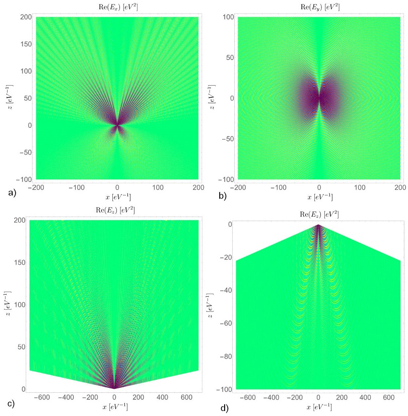
We finalize this section by presenting plots for the real part of the electric fields (41) and (62) in their corresponding regions

Figure 2 The electric field pattern (real part) in the x - z plane for a vertically oriented point dipole with single frequency
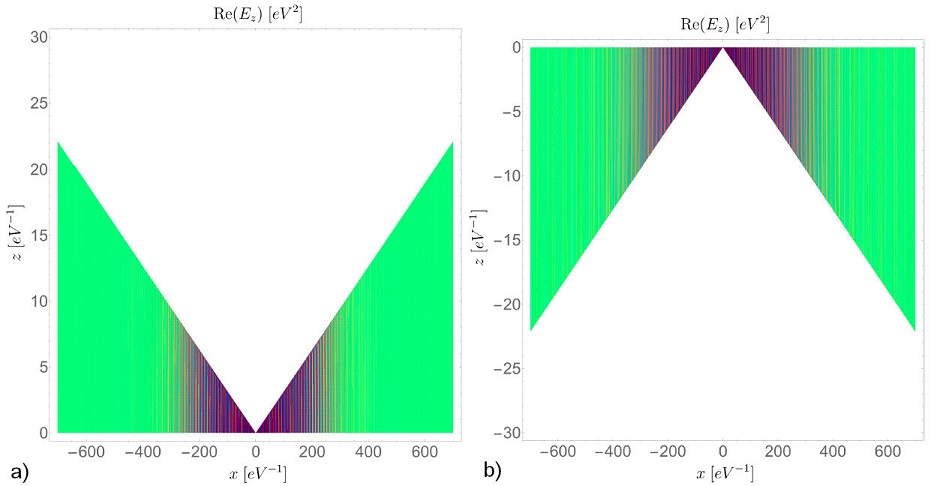
Recalling from Eq. (62) that only the z component of the electric field contributes to the cylindrical waves, we need to employ the discarding angles given by Eqs. (29) to split the space into the regions

Figure 3 The electric field pattern (real part) in the x - z plane for a vertically oriented point dipole with single frequency
4 Angular distribution, total radiated power and energy transport
4.1 The parameters
With the purpose of illustrating our results with some numerical estimations we need to fix the parameters defining our setup. Our choice is motivated by the fact that current magnetoelectric media are of great interest in atomic physics and optics, therefore we think as a dipolar source an atom with a given dipolar moment p, whose emission spectrum goes from the near infrared to the near ultraviolet. Furthermore, the magnetoelectric coupling is usually very small (of the order of the fine structure constant for TIs), so that appreciable effects will appear near the interface. In this way we have chosen the distance between the dipole and the observer to be lesser than 1 mm. For all cases in the following numerical estimations, with the exception of Fig. 6, we take the frequency
4.2 Angular distribution for the radiation in the region
In this subsection we obtain the angular distribution of the radiated power associated to the electric field given by Eqs. (41) for the region
where
The result for our dipole p is
where
At this stage it is important to emphasize that our result in Eq. (65) shows that
Now, we analyze the angular distribution of the radiated power (65) for the Case (—) discussed in Sec. 3.2.1, when the electric field has a single phase. Making this choice in Eq. (65), we obtain
Notice that the factor
On the other hand, for the Case (+), when the electric field includes two different phases, we obtain the angular distribution
which present additional contributions to the angular distribution with respect to those in SED. They arise from the last term in Eq. (67). Furthermore, as opposed to the previous case, the angular distribution now depends explicitly on the dipole position z0. Let us observe that the minimum value -1 of
The behavior of the angular distribution (67) is shown in Fig. 4. In each case, the electric dipole is located at z0 > 0 and the interface corresponds to the line

Figure 4 Angular distribution of the radiated power
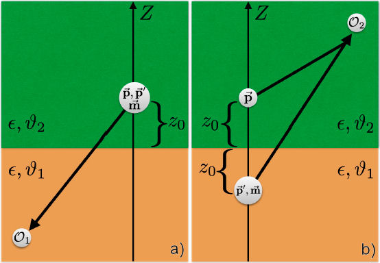
Even though the method of images does not generalize to the time dependent case, a qualitative interpretation for the radiation patterns described above can be given by extending to the quasi-static approximation the characterization of a point charge located in front of a magnetoelectric medium in terms of electric and magnetic images presented in detail in Ref. [57]. In this way, the full description of the MEE of a dipole located in front of a planar medium includes electric and magnetic image dipoles. Let us first deal with the Case (—), which corresponds to the situation when the electric dipole and the observer are in different semi-spaces, i.e. the dipole is located at

Figure 5 a) Illustration of the Case (—), where the radiation (black thick arrows) has a single phase, which is the one of standard ED, when the observer
4.3 Power radiated in the region
In order to compare the magnitude of the radiation in the ϑ-medium with respect to the SED case it is convenient to introduce what we call the enhancement factor
Next we calculate the power radiated for the angular distributions (66) and (67) in the region
A good estimation of the enhancement factor is obtained writing
which can be larger (smaller) than one according to
Now, we repeat the calculation for the angular distribution of the Case (+) given by Eq. (67), which is more interesting. After integrating over the solid angle Ω for
The main difference with respect to the power radiated in the LH is that now
The Eq. (72) tells us that there are no divergences in Eq. (70) when the electric dipole is very close to the interface. Since for all practical purpose
As we can calculate from Eq. (73), the enhancement factor
4.4 Energy transport in the intermediate region of
In this subsection we discuss the energy flux in the region
As pointed out in Ref. [47], the separation of the electric field (62) in these two components is not significant since they do not constitute independent solutions of Maxwell equations. Recalling Eq. (63) for the time-averaged Poynting vector
to first order in ξ. In the above linear expansion we require
We observe that these fluxes are independent of the position of the dipole. In Eqs. (74) and (75) we encounter two different terms: one modulated by
Two remarks are now in order: (i) For a fixed set of parameters, Eqs. (74) and (75) yields
since
On the contrary, when
Next we perform some numerical estimations of Eq. (75) shown in Table I. There we refer to the setup described in the beginning of Sec. 2, for the case where medium 1 is a regular insulator with n = 2(1.87, ), μ = 1 and ϑ = 0, while medium 2 corresponds to different magnetoelectric media with the same refraction index and permeability and whose value of
Table I The energy flux very close to the interface
| ϑ-medium | n |
|
|
|
|
|
|---|---|---|---|---|---|---|
| TlBiSe2 | 2 | 11α | 4.0×10⁻⁴ | 6.64 | 6.64 | 6.63 |
| TbPO4 | 1.87 | 0.22 | 3.5×10⁻³ | 6.21 | 6.21 | 6.18 |
| Hyp. I | 2 | 0.5 | 1.5×10⁻² | 6.74 | 6.73 | 6.63 |
| Hyp. II | 2 | 1 | 5.9×10⁻² | 7.03 | 6.97 | 6.63 |
| Hyp. III | 2 | 5 | 6.1×10⁻¹ | 8.53 | 7.89 | 6.63 |
5 Summary and conclusions
We discuss the radiation produced by a point-like electric dipole oriented perpendicular to and at a distance z0 from the interface which separates two planar semi-infinite non-magnetic magnetoelectric media with the same permittivity, whose electromagnetic response obeys the modified Maxwell equations (4) and (5) of ϑ-electrodynamics. The choice
Due to the presence of the ϑ-media we find modifications in the angular distribution of the radiation given by Eq. (65) and illustrated in Fig. 4. Noticeable interference effects are manifest in the upper hemisphere when the observer is in the same region of the dipole. On the contrary, no interference occurs when the observer and the dipole are not in the same region, in which case the angular distribution looks similar to that of a dipole in a homogeneous media, except for important changes in its magnitude. Such different interference effects say that the system distinguishes whether the electric dipole and the observer are in the same semi-space or not, corresponding to the Cases (+) and (—) respectively, discussed at the end of Subsec. 4.2.
Starting from the far-field approximation of the electric field we have correctly identified the Fresnel coefficients at the interface by making use of the angular spectrum representation [49] together with the results of Ref. [48] dealing with wave propagation in layered topological insulators.
The modifications of the angular distribution in the region
Regarding the region
In order to stress their similarities and differences we give some comparison between the dipolar radiation studied in this work which includes a magnetoelectric medium, and that produced in the presence of two standard insulators with a planar interface and different permittivities
Let us emphasize once again that our methods can be applied to study the radiation in all materials whose macroscopic electromagnetic response is described by ϑ-electrodynamics. This includes any magnetoelectric medium, which can be found among a wide range of ferromagnetic, ferroelectric, multiferroic materials and topological insulators, for example. Our results contribute to the list of uncovered consequences of the magnetolelectric effect, which still remains far from experimental confirmation. Generally speaking, the parameter


 nueva página del texto (beta)


