SciELO - Scientific Electronic Library Online

 
vol.69 número4C-V model of CdS/CdTe thin-film solar cells dependent on applied voltage frequencyGround state dynamically stable phases for fluorine in the TPa pressure regime by evolutionary algorithms índice de autoresíndice de materiabúsqueda de artículos
Home Pagelista alfabética de revistas  

Servicios Personalizados

Revista

Articulo

Indicadores

Links relacionados

  • No hay artículos similaresSimilares en SciELO

Compartir


Revista mexicana de física

versión impresa ISSN 0035-001X

Rev. mex. fis. vol.69 no.4 México jul./ago. 2023  Epub 19-Nov-2024

https://doi.org/10.31349/revmexfis.69.041605 

Solid state physics

Magnetostatic model for magnetic particle aggregates with cylindrical shapes

V. H. Carrera-Escobedoa 

K. Hintze-Maldonadoa 

A. Encinasa 

a División de Materiales Avanzados, Instituto Potosino de Investigación Científica y Tecnológica A. C., Camino a la Presa de San José 2055, Lomas 4ta Secc., 78216 San Luis Potosí, S.L.P., Mexico.


ABSTRACT

Building micro and macro sized structures using compacted magnetic nanoparticles is a widely used approach that has proven a great potential as the basis for novel materials made by design. These materials are made by compactation of soft magnetic particles in the nano or micrometer sizes and their macroscopic properties are mostly governed by magnetostatic effects and the combination of the intervening shapes, namely those of the individual particles and that of the piece made with these particles. Herein a simplified mean-field model is presented to describe the magnetostatic effects in soft magnetic composites with cylindrical macroscopic shape made of densely packed ideal spherical soft magnetic particles. The model allows calculating the main magnetic parameters of the system as well as their most relevant tendencies as a function of its main parameters. Furthermore, the model has also been successfully applied to arrays of interacting macroscopic shapes, which provides a further controllable magnetic parameter.

Keywords: Nanoparticles; magnetostatic effects; soft magnetic particles

1 Introduction

Using magnetic particles as building blocks to construct more complex structures is a well known approach to fabricate materials with tailored magnetic properties. A well developed and extensively studied class of such materials are the so-called soft magnetic composites[1], in which magnetic powders of a soft magnetic material are compacted to form a larger, macroscopic shape. These materials are very interesting for their application as soft materials [2, 3]. Such constructions using densely packed particles has also been explored with magnetic nanoparticles [4, 5, 6]. Another interesting example was reported by Merk, et al.[7], where they found that using wood as a template, an anisotropic composite material is obtained, related to the hierarchical structure of wood. In another report, magnetic particles have been printed using an inkjet printer leading to an anisotropic printed material [8]. These reports show that when particles are packed in a given geometry, the assembly tends to show a magnetic anisotropy having the symmetry of the enveloping volume [9, 10]. Interestingly, this has been observed when nearly spherical isotropic particles are packed together. This anisotropy is due to magnetostatic effects, in particular demagnetizing dipolar interaction between the particles. Moreover, there is evidence showing that changing the shape of the particle packing and forming arrays of such packings can lead to novel anisotropy properties which show symmetry properties derived from both the shape of the packing and the array formed with them [4, 5, 7, 8, 11].

Calculation of the magnetic anisotropy properties of these systems is complex and requires specialized software and computing resources [12]. In this sense, simple model calculations capable of providing a clear and practical view of the relation between the packing geometries and the resulting magnetic properties are needed. Specially given the current progress of current fabrication techniques that provide an unprecedented control at the nanoscale to produce extremely complex particle assemblies. In this sense, herein we propose and validate a simple mean-field model for spherical particle assemblies which accounts for the magnetostatic properties of these systems. These properties allow to obtain the magnetic shape anisotropy of the assembly. Moreover, we focus our analysis to cylinder shaped assemblies of packed spherical particles. The cylindrical shape includes the tube (hollow cylinder) and the homogeneous cylinder. For both cases, it is possible to use approximate expressions for the demagnetizing factors leading to simple analytical expressions. The model is extended to include the more complex case of a two dimensional array of cylinder shaped assemblies of packed spherical particles. The results show that despite using spherical isotropic particles, the assembly shows an effective magnetic anisotropy that originates in the dipolar interaction between the magnetized particles. The symmetry and magnitude of this anisotropy depends explicitly on the geometrical parameters of the system.

Overall, the model is shown to lead to the expected limiting cases without any inconsistency. Moreover, we show that it allows to vary independently all the relevant parameters of the system. The results provide insight into the role played by each parameter and sheds light to possible mechanisms viable to control and tailor the magnetic anisotropy of these particle assemblies.

2 Model for cylinder shaped assemblies of packed spherical particles

When forming a cylindrical packing of particles, we consider two main geometries: a homogeneous circular cylinder and the hollow circular cylinder, or tube, as the ones depicted schematically in Fig. 1a). In the following we assume that the long axis is along the z-axis. For the cylindrical packing we have the following parameters: cylinder diameter ϕ, height h, the corresponding aspect ratio τ=h/ϕ and the packing fraction P, which is the fraction of the total volume of the cylinder occupied by the particles. For the case of the tubular structure we have the internal and external radii r1 and r2 (r2=ϕ/2), respectively. Additionally, for the case of several cylinders (tubes) we use the center to center distance between them D and the reduced distance d=D/ϕ.
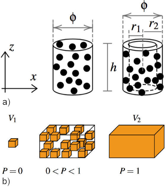
Figure 1 a) Two cylindrical packing of particles, a homogeneous cylinder and a tube, along with their main geometrical parameters. b) Particle assembly starting from the single isolated particle corresponding to a zero packing fraction, intermediate packing fractions and the completely filled volume P = 1.  

To describe the magnetostatic effects of these systems we use the formulation of the effective demagnetizing field for particle assemblies reported by Martínez-Huerta, et al.[13]. The model considers the assembly as a collection of identical particles contained in a bounding outer volume as ilustrated in 1b). This particle is the elemental building block and it is characterized by its volume V1 and demagnetizing factor N 1. Hereafter, and in order to evaluate the magnitude of the relevant parameters, it is assumed that the individual particles are fully saturated. The external volume V2 has a demagnetizing factor N 2. The density of particles is taken into account using the volume packing fraction P occupied by the particles in the external volume. For such particle assemblies, the effective demagnetizing field (HDt), or the effective (total) demagnetizing factor (NDt=HDt/μ0Ms) is written as [13],

NDt=N1+(N2-N1)P. (1)

This expression corresponds to the sum of the demagnetizing effects of the single elementary particle, namely the first term N 1, and the effects of the interaction between particles which are bounded by the external volume occupying a volume fraction P, which is the second term (N2-N1)P. As seen from Fig. 1b), in the limit where P0, Eq. (1) reduces to the case of a single isolated and non interacting particle (NDt=N1). Whereas in the other limit, P1, Eq. (1) is reduced to the demagnetizing factor of the homogeneous and continuous outer volume V2, this is NDt=N2. In practice, the geometry of the particles will determine the maximum attainable packing fraction, which for spheres is less than 1. Indeed, the maximum 3D packing fraction for spheres can have different values: for the so-called close random packing (vibrated bead) of identical spheres it is 0.625-0.64 while the densest regular packing is 0.7405 [14, 15].

Using these effective demagnetizing factors, the total magnetostatic or shape anisotropy can be determined. To this end, we recall that the shape anisotropy is defined as ESt=μ0Ms2ΔNDt, where ΔNDt=ΔNDtx-ΔNDtz. Here it is assumed that the easy axis is along the long axis of the cylinder, in this case the z axis while the hard axis is along the x-axis, see Fig. 1a).

Using Eq. (1) to calculate ΔNDt, we obtain

ΔNDt=ΔN1+(ΔN2-ΔN1)P. (2)

This expression is proportional to the anisotropy energy ESt, so that in the following we use and refer to the effective anisotropy as ΔNDt=ESt/(μ0Ms2). Equation (2) shows that the total anisotropy of the assembly is the result of the competition between the easy axes of the elementary particle and the outer volume. The competition is weighted by the packing fractions. Indeed, at low packing fractions the easy axis approaches that of the single isolated particle as P0, and ΔNDt=ΔN1. While, in the opposite limit, as P1, the easy axis will approach that of the outer volume, so that ΔNDtΔN1 [13].

This model was used to study the particular cases where the external volume was a circular cylinder as well as a tube or hollow cylinder filled with a volume fraction P with spherical particles, as shown in Fig. 1a). Then, the model was extended to treat the case of a 2D array of such parallel tubes/cylinders packing of spheres, as those shown schematically in Fig. 2.
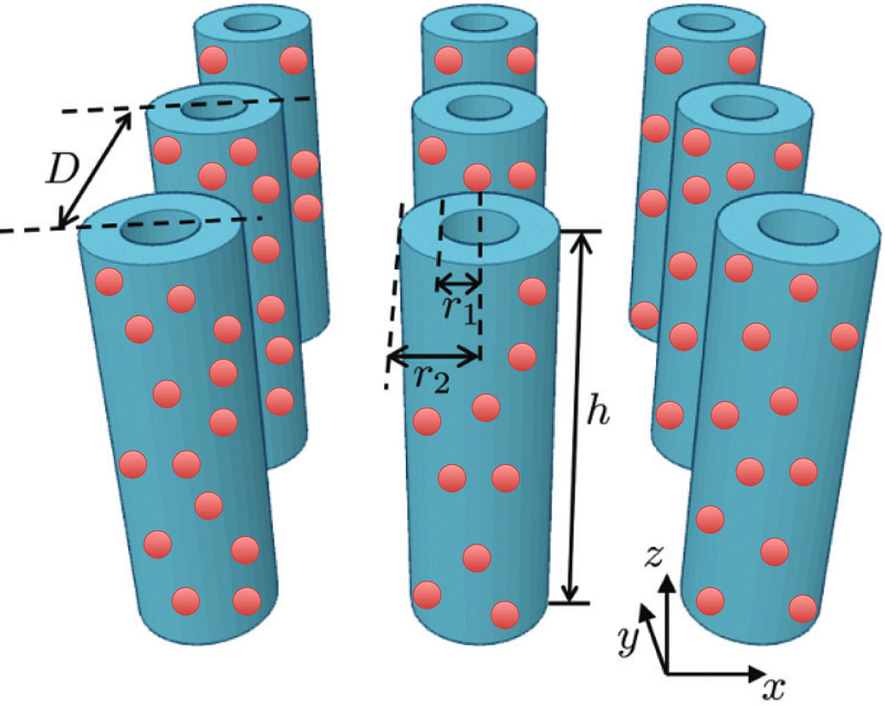
Figure 2 2D array of parallel tubes each containing spherical particles with a volume fraction P 1. The geometrical parameters of the system are the internal and external radii (r1,r2), their height h and the center-to-center distance D between the tubes. 

2.1 Cylinder shaped assemblies of packed spherical particles

Consider an assembly of spherical particles which have no magnetocrystalline anisotropy. The demagnetizing factor for this volume is Ni=1/3,  i=x,y,z. The external volume is a circular tube with β=r1/r2 as the ratio between inner and outer radii and where the homogeneous (or solid) cylinder corresponds to the particular case of the tube when r1=0 and β=0. In the following, we analyze the case when the external volume is a tube, which includes the particular case of the solid cylinder. The demagnetizing factor for the tube is N2={N2x,N2x,N2z}, where by symmetry N2x=N2y.

Since the particles are spherical, ΔN1=0. Additionally, taking advantage of the symmetry in the xy-plane, we have that 2Nx+Nz=1 and ΔN2=(1-3N2z)/2. Therefore, Eq. (2) for the effective anisotropy can be expressed as,

ΔNDt=1-3NzP2. (3)

Hereon, we drop the number 2 in the sub-index, so N2z=Nz. For Nz we use the approximate expression for tubes proposed by Nam, et al.[16]; that relates the demagnetizing factor the tube with the one of the solid, homogeneous cylinder Ncz,

Nz=Ncz(1-β2). (4)

While the axial demagnetizing factor of a homogeneous circular cylinder is computed as a function of the aspect ratio τ=h/ϕ using the approximate expression proposed by Sato and Ishii[17], namely,

Ncz=11+4τπ. (5)

Sustitution of Eqs. (4) and (5) in (3) leads to the following approximate analytical expression for the shape anisotropy of a tube containg spherical particles,

ΔNDt=1-3(1-β2)1+4τπP2. (6)

As we can see, the effective anisotropy depends on the aspect ratio of the tube, τ0, as well as the thickness of the tube wall (β) and the volume fraction occupied by the particles and subject to 0β<1 y 0P1.

2.2 Two dimensional array of cylinder shaped assemblies of packed spherical particles

We now extend the model for the case of a two dimensional array of cylinder shaped assemblies of packed spherical particles. This case leads to the interaction between tubes. Figure 2 shows a 2D array of parallel tubes each containing spherical particles. In this case, we have the same parameters (inner and outer radii, height) with the addition of the center-to-center distance D. For this system we have two packing fractions: P 1 corresponding to the volume fraction of the spherical particles in each tube, and a second packing fraction P 2 corresponding to the tubes in the 2D array.

This system can be described using three different volumes and their respective demagnetizing factors. As previously, the first volume is that of the spherical particles, N 1. The next volume is that of the cylindrical tube, N 2 and now we include a third volume which corresponds to a thin film, N 3, that contains the 2D array. Figure 2 depicts the system, where the same geometrical parameters are used as before with the addition of the center-to-center distance between cylinders D.

To extend the model we start with Eq. (1). Since the tubes N 2 form an array, we call N'2 the effective demagnetizing factor of the tube array, so Eq. (1) reads as,

NDt=N1+(N'2-N1)P1, (7)

Now, for N'2 we use the same equation but introducing the third volume (thin film) and the packing fraction occupied by the tube array in the film (P2): N'2=N2+(N3-N2)P2. Substitution in Eq. (7) and rearranging terms, we obtain the expression for this system,

NDt=N1+(N2-N1)P1+(N3-N2)P1P2, (8)

as in the previous section, the effective anisotropy is given as ΔNDt, this is,

ΔNDt=ΔN1+(ΔN2-ΔN1)P1+(ΔN3-ΔN2)P1P2, (9)

As done before, from this expression it is possible to analyze the most important limiting cases. The first one is when P10, that corresponds to a single particle and we see that indeed, the previous expression reduces to ΔNDt=ΔN1. If now we take the limit P11, which corresponds to a homogeneous tube, we can see that the terms containing ΔN1 are eliminated and we obtain the expression corresponding to a 2D array of tubes having a packing fraction P 2 analogue to Eq. (1). Taking now P20 in Eq. (9), we recover the case of a single tube containing spherical particles. For the limit P21, we have that the tubes ideally fill entirely the volume of the thin film. From Eqs. (8) and (9) we see that the terms containing N 2 are eliminated and we obtain the expression for a film (N 3) containing spherical particles (N 1) that occupy a volume fraction P 1. These are the four expected limits.

The corresponding demagnetizing factors can be entered in Eq. (9). For the spheres and tubes, we use the same as before and for the thin film N3={0,0,1}.

Taking again ΔN=Nx-Nz, we have that ΔN1=0, ΔN2=(1-3Nz)/2 y ΔN3=-1. This leads to,

ΔNDt=12-32NzP1-32(1-Nz)P2P1. (10)

To further simplify, we use Eqs. (4) and (5) for N z as before. For the packing fraction of the tubes in the thin film (P 2) we use the expression reported previously for a 2D hexagonal array of tubes with external diameter ϕ separated by a center-to-center distance D and reduced distance as d=D/ϕ [18],

P2=π23(1-β2)d2. (11)

Note that the first term in Eq. (10) reduces to Eq. (6). Substitution of the expressions for N z and P 2 leads to the following analytical expression for the (reduced) effective anisotropy,

ΔNDt=1-3(1-β2)1+4τπP12-π321-(1-β2)1+4τπ1-β2d2P12. (12)

This expression contains the sum of two terms and they both correspond to dipolar interaction field contributions. Comparing to Eq. (9), the first term in Eq. (12) is the dipolar interaction between the particles in a given tube. While the second term represents the dipolar interaction between tubes in the 2D array. Here again ΔN1=0 as the spherical particles have zero shape anisotropy. Then the anisotropy in this systems originates in the dipolar interaction between the constituent particles and their spatial arrangement.

We note that P1/2 appears multiplying both terms, which, as discussed in the previous section, will simply modulate the amplitude of the effective anisotropy. Besides from P 1, the anisotropy depends on the width of the tube wall (β), the tube aspect ratio (τ) and the reduced center-to-center distance (d). The particular case of a 2D array of continuous/homogeneous tubes is obtained when P1=1, so Eq. (12) reduces to the expression reported previously [19].

3 Results and discussion

In the previous sections analytical approximate expressions have been obtained for the 2D array of tube shaped spherical particle arrays. These expressions can be easily evaluated making it practical and easy to obtain curves of the different quantities of interest. We analyze first the case of a single cylinder shaped assembly of packed spherical particles, and then we consider the 2D array of such cylinder shaped assemblies.

3.1 Single cylinder shaped assembly of packed spherical particles

From the expression derived in the previous sections it is possible to analyze the properties of the effective demagnetizing field and the effective shape anisotropy of the system.

As a first point, we note that the system has a finite magnetic anisotropy despite the fact that it is built using isotropic spherical particles. Indeed, despite ΔN1=0, ΔNDt0 implying a magnetic shape anisotropy. This anisotropy follows from the dipolar interaction between the spherical particles and can be written in general form using Eq. (2), namely,

ΔNDt=ΔN2P. (13)

We can see that for P0 we obtain the expected limit for a single isotropic particle, ΔNDt=0. While for P1 we obtain the shape anisotropy of the homogeneous tube of arbitrary aspect ratio ΔNDt=ΔN2.

From Eq. (6) it is possible to derive some important limiting values of the effective shape anisotropy. The first important limit is for very tall tubes, this is τ. In this case, ΔN2=1/2 and

ΔNDt=P2. (14)

The case of an infinitely tall homogeneous cylinder follows when P = 1, which leads to the well known value of the shape anisotropy of ΔNDt=1/2. This anisotropy value of 1/2 is an upper bound since it is obtained for P = 1, for packed spheres this value is not achieved.

Another important property is the sign of ΔNDt as it reflects the direction of the anisotropy easy axis. As pointed out above, it has been assumed that the easy axis is along the z-axis which is parallel to the long axis of the tube and the hard axis is perpendicular or in the xy-plane. Since the anisotropy is calculated as ΔNDt=Nx-Nz, it is clear that the easy axis is along the z-axis when Nx>Nz and inversely, it is perpendicular to the tube axis when Nz>Nx.

Analyzing Eq. (3), we can see that the sign of ΔNDt is determined by the quantity in the square brackets. Taking 1-3Nz=0 it follows that Nz=1/3 and ΔNDt=0 which corresponds to the isotropic case. However, if Nz<1/3 then ΔNDt>0, and when Nz>1/3 it follows that ΔNDt<0.

To analyze this in more detail, N z has been calculated as a function of the aspect ratio using Eqs. (4) and (5), for different values of the tube wall thickness β, including the case of the homogeneous cylinder (β=0). The results are shown in Fig. 3.
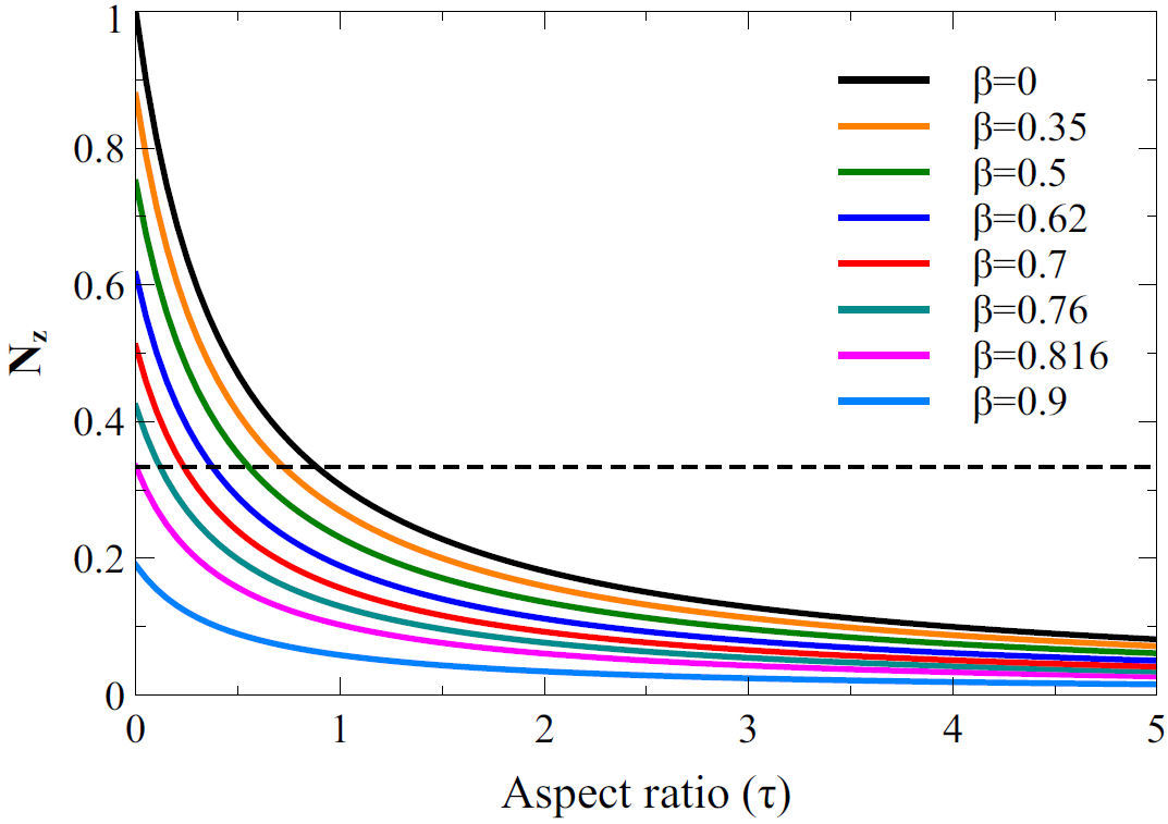
Figure 3 Axial demagnetizing factor, N z as a function of the aspect ratio τ, for different tube wall thicknesses β. For reference, the horizontal dashed line indicates the case where Nz=1/3

As seen in the figure, the curves show the same general variation. They reach their maximum value when τ=0 and they decrease as the aspect ratio increases, tending asymptotically to zero for large values of τ. For the particular case of the homogeneous cylinder (β=0), the well known curve for N z is obtained [17]. However, for larger values of β the corresponding curves shift downwards, so that for a given value of the aspect ratio, the corresponding demagnetizing factor decreases. This behaviour is characteristic for continuous and homogeneous tubes [18]. Relating the values of the demagnetizing factor to the anisotropy, we can see that N z takes values larger and smaller than 1/3, shown as a horizontal dashed line in Fig. 3. However, the value of the aspect ratio at which N z =1/3 depends on the value of β. In particular, for values of β0.816N z does not take values larger than 1/3. This will be discussed in more detail in the following sections, however at this point we note that this implies that when the tube wall thickness decreases, β1, the tube can no longer have its easy axis perpendicular to the z-axis regardless of the value of τ.

Besides the effects of the aspect ratio and tube wall thickness on the demagnetizing factor and the resulting magnetic anisotropy, the packing fraction of the particles is another important parameter. Consider first the limiting case P = 1 and the material is a continuous and homogeneous tube (β0) or cylinder (β=0). This case serves as a reference to compare with previous results reported for tubes [19].

Figure 4a) shows the reduced effective anisotropy as a function of the aspect ratio for different tube wall thickness β for the particular case of the continuous tube (P = 1). As seen in the figure, the curves show an increase of the anisotropy with the aspect ratio. However, this increase is faster as the value of β increases, corresponding to a reduction of the tube wall thickness. So that a reduction of the tube wall thickness enhances the shape anisotropy of the tube [18, 19].
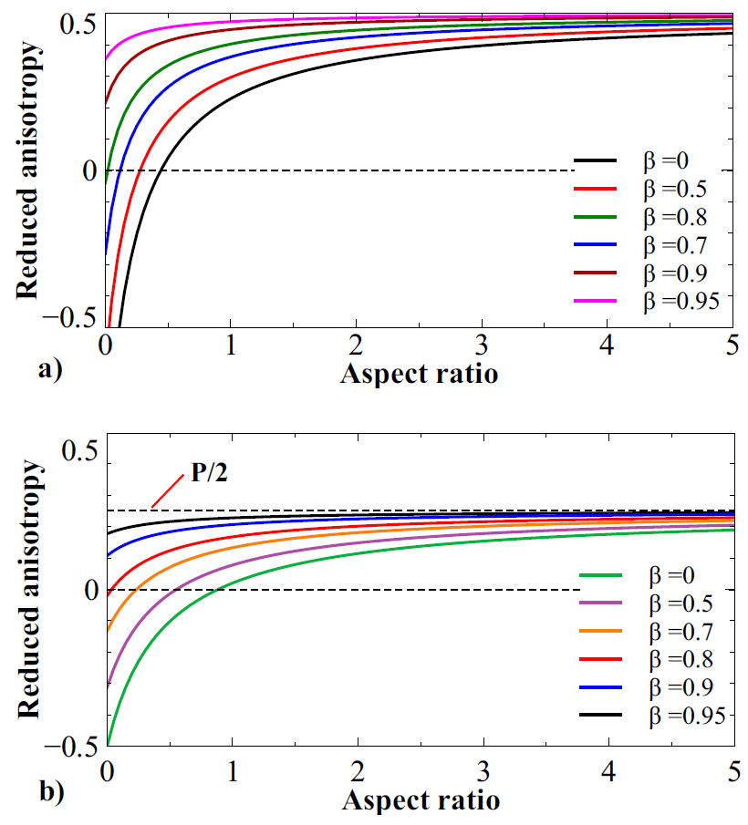
Figure 4 Reduced effective anisotropy as a function of the aspect ratio for different tube wall thickness β for a) the particular case of the continuous tube P = 1 and b)a particle volume fraction of P = 0.5.  

From the figure it can also be noted that for small values of β, the anisotropy goes from positive to negative as the aspect ratio decreases. This change in sign corresponds to a change of the easy axis direction below a critical aspect ratio. For an homogeneous (continuous) cylinder this critical value has a well-known value of τ=0.906 [19]. However, as the value of β increases, the value of the aspect ratio where the anisotropy is equal to zero decreases, and for β>0.8 it no longer reaches zero. In this case, the easy axis no longer reverses regardless of the aspect ratio. As expected, these results (P = 1) are equivalent to those reported for continuous tubes [19]. Regarding the effect of the packing fraction, we note from Eq. (6) that the packing fraction is a multiplicative factor and therefore it only modulates the amplitude of the total anisotropy. As expected, the anisotropy is zero when P = 0, which is the case of a single isotropic sphere and it reaches its maximum value of 1/2 for P = 1 for large aspect ratio values. This modulating effect of the packing fraction is shown in Fig. 4b), where the total anisotropy as a function of the aspect ratio for different values of the tube wall thickness is shown for the particular case where P = 0.5. Comparing to the results shown in Fig. 4a), we see the same behavior but, as expected, the amplitude is reduced. We can see that the maximum value of the anisotropy is P/2.

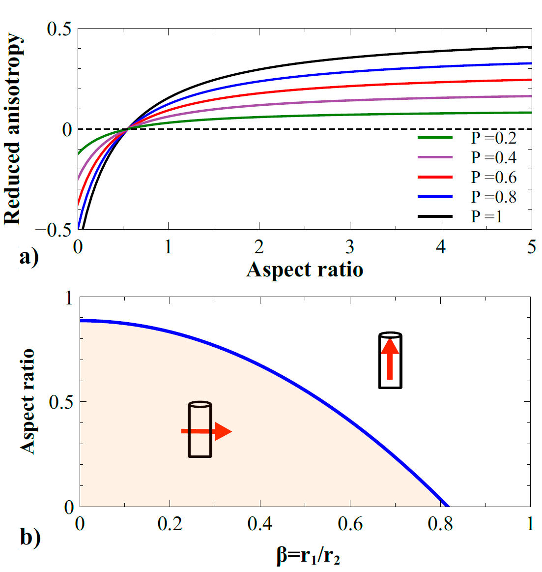
To gain further insight on the role of the packing fraction the effective anisotropy was calculated as a function of the aspect ratio while keeping the value of the tube wall thickness constant (β=0.5) for different values of the packing fraction. The results are shown in Fig. 5a). As seen from the figure, the volume fraction simply modulates the amplitude of the anisotropy and its general variation with the aspect ratio is independent. Here we note that the point where the anisotropy is zero is the same regardless of the value of P and therefore the reorientation of the easy axis only depends on τ y β. This is clear in Eq. (6), where a change of sign in ΔNDt can only result from the quantity in the brackets.

Figure 5. a) Reduced effective anisotropy as a function of the aspect ratio for different values of the packing fraction P for the particular case of β=0.5. b) Zero anisotropy curve, showing the critical aspect ratio value at which the anisotropy is zero as a function of the tube wall thickness β.  

To find the condition for the isotropic point, we equate Eq. (6) to zero an solve to find the critical aspect ratio τc, which is given by:

τc=3π423-β2. (15)

This expression is equal to Eq. (13) in [19] which reflects a quadratic dependence on β. This expression can be evaluated to obtain the zero anisotropy curve for the critical aspect ratio as a function of β, which is shown in Fig. 5b), where, as shown schematically, those values above the curve correspond to an easy axis parallel to the tube axial axis, ΔNDt>0, while those values below the curve correspond to an easy axis perpendicular to the tube axis, ΔNDt<0. In addition, we note that the curve goes to zero at β0.8. This means that above this value of β the total anisotropy has the easy axis parallel to the tube axis (ΔNDt>0) regardless of the value of the aspect ratio. This is the same result pointed out in Fig. 4a) and b), where above a value of β0.8 the anisotropy no longer reaches negative values. Taking τc=0 in Eq. (15) we obtain the value of β above which it is no longer possible to reverse the easy axis by changing the tube aspect ratio. This value is βc2=2/3 or βc=0.82.

This condition related to the tube wall thickness (β) as well as Eq. (15) have already been identified and predicted for the case of a 2D array of homogeneous tubes [15]. However, for the cylinder shaped assembly of packed spherical particles considered herein, this diagram becomes important since it is independent of the packing fraction. This is, to tailor the easy axis direction it is only necessary to adjust τ and β following Eq. (15), regardless of the volume packing of the spherical particles.

3.2 2D array of cylinder shaped assembly of packed spherical particles

In contrast to the single tube/cylinder, the 2D array introduces additional contributions to the effective anisotropy which originate in the classical dipolar interaction between the tubes/cylinders.

Equation Eq. (12) shows the sum of two terms. The first one is the interaction between spherical particles in a given tube. This is the case already analyzed in the previous section. The second term is the dipolar interaction between tubes in the 2D array. The second term is always negative which indicates that this interaction term favors an easy anisotropy axis perpendicular to the tube axis, or in the xy-plane. The amplitud of this term is modulated by both packing fractions: P 1 of the particles in the tube and P 2 volume occupied by the tubes in the thin film containing the 2D array.

To analyze the behavior and the effects of this second term, we have calculated separately the values of this term alone as well as the total anisotropy, Eq. (12). For this calculation, the tube aspect ratio was kept constant at a value of τ=10, and we varied the tube wall thickness β.

The results are plotted as a function of the inverse of the reduced distance, this is 1/d since it is more practical. Indeed, it varies between [ 0,1], the value 1/d = 0 corresponds to the case were the tube and infinitely apart and the interaction goes to zero. Inversely, when 1/d = 1 corresponds to the limiting case where the tubes touch and its the smallest possible distance between them.

Figure 6a) and b) show the reduced interaction field, (c) and (d) the reduced anisotropy as a function of the inverse reduced distance (1/d) for different values of the tube wall thickness β and a constant aspect ratio of τ=10. In (a) and (c) P 1=1, while (b) and (d) were obtained for P 1=0.5.
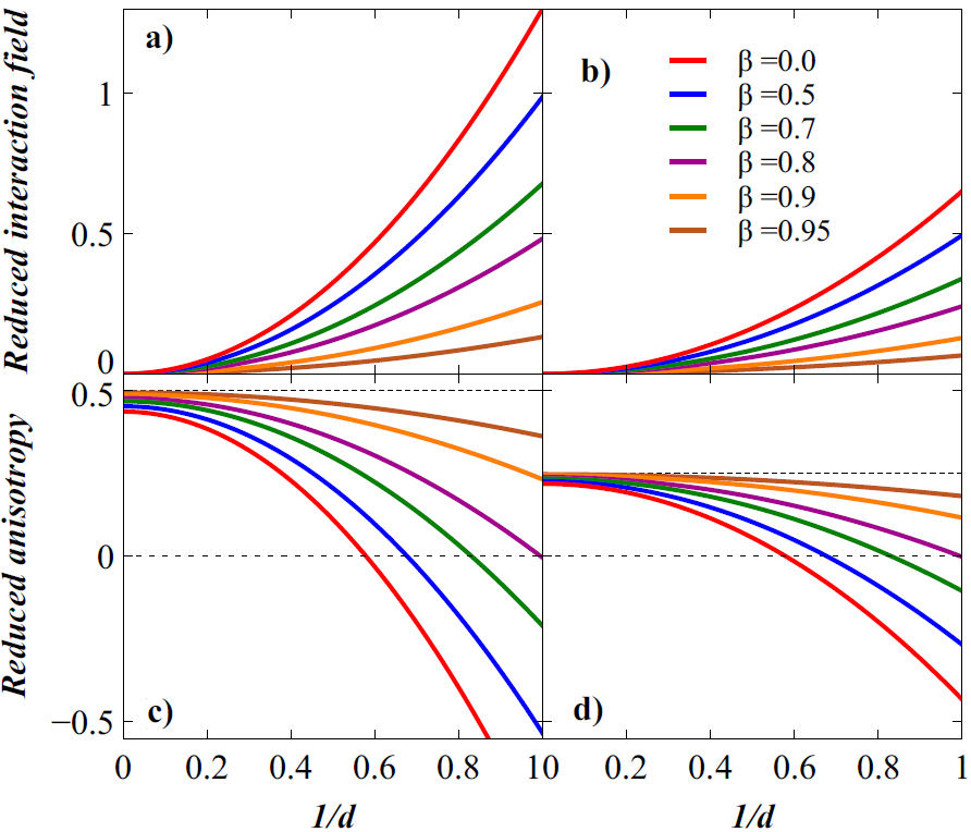
Figure 6 a) and b) Reduced interaction field, c) and d) reduced anisotropy as a function of the inverse reduced distance 1/d for different values of the tube wall thickness β and a constant aspect ratio of τ=10. In a) and c) P 1 = 1, while b) and d) were obtained for P 1 = 0.5. 

For the interaction field between the tubes in the 2D array, Fig. 6a), it goes to zero when the tubes are separated (1/d=0). When the distance between them is reduced, the interaction field increases following a quadratic behavior (1/d2), until reaching its highest value when the tubes come into contact (1/d = 1). We can see that as the tube wall thickness decreases, β increases; the magnitude of the interaction field decreases. This is similar to the effect described for a single tube in the previous section, this is, the anisotropy of the tube is reinforced when the tube wall becomes thinner.

As pointed out before, the amplitude of both terms in Eq. (12) is modulated by the factor P1/2. To this end we compare the reduced interaction field for P 1 =1 a P 1 =0.5 in 6a) and b). As expected, the same behavior is obtained in both cases, the only change being the amplitude of the interaction field.

Regarding the effective magnetic anisotropy, this is shown in Fig. 6c) and d). The overall behavior reflects the sum of the shape anisotropy, the first term in Eq. (12), and the dipolar interaction between tubes, second term in Eq. (12), which is preceded by a negative sign. As seen in the figure, the total anisotropy is maximal when the tubes are apart, 1/d = 0, and as the distance between them is reduced, the interaction between them (with its negative sign) leads to a reduction of the total anisotropy, leading to a change in sign for certain values of β. At large separation, 1/d = 0, the effective anisotropy reduces to that of the single (non-interacting) tube, which as discussed above, increases as the width of the tube wall decreases (β approaches 1), in agreement with the results shown in Fig. 4.

As mentioned before, the amplitude of the effective anisotropy is proportional to the packing fraction of the spheres P1/2, which also defines the upper limit value of the anisotropy. This is shown as horizontal dashed lines in Fig. 6c) and d). So by increasing the distance between tubes, 1/d0, we see that the anisotropy tends to this upper limit and as this distance is reduced (increasing1/d), the anisotropy decreases as the interaction field becomes stronger. The rate at which the anisotropy decreases and changes sign, 1/d = 0, depends on the tube wall thickness β.

As already mentioned, the packing fraction of the particles in the tube P1 modulates the amplitude of the effective anisotropy but its not expected to change its behavior. To verify this we have calculated the effective anisotropy as a function of the inverse of the reduced distance for different packing fractions of the spherical particles in the tubes with constant tube aspect ratio τ = 10 and thickness of the tube wall β =0.2. The results are shown in Fig. 7 where we verify that the volume fraction of the particles in the tube only change the amplitude of the anisotropy. For the case shown in Fig. 7 we see that the point where the anisotropy is zero is the same for all the values of P 1. This is in agreement with the results from the previous section, in particular those shown in Fig. 5a).
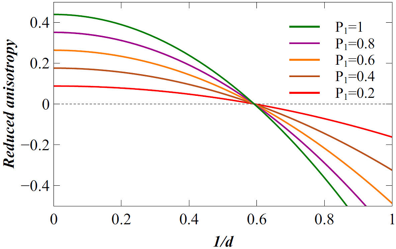
Figure 7 Reduced anisotropy as a function of the inverse of the reduced distance for different packing fractions of the spherical particles in the tubes P 1 with constant tube aspect ratio τ=10 and thickness of the tube wall β=0.2.  

As observed for the case of a single tube, the effective anisotropy shows a change of sign, as seen in Fig. 6c), d) and Fig. 7. However, this does not happen above certain values of β. As before, the change in sign indicates that the easy axis direction changes from being parallel to the tube axis (positive anisotropy) to perpendicular to the axis (negative anisotropy). However, this easy axis reorientation is inhibited as the tube wall thickness decreases. To find the conditions where the effective anisotropy vanishes, we equate to zero Eq. (12) and solve to find the critical aspect ratio τc, leading to,

τc=π4π32d21-β2-3π32d21-β2-11-β2-1. (16)

This expression shows that the critical aspect ratio (τc0) is given solely by the tube wall thickness (0<β<1) and the reduced distance between tubes (d1).

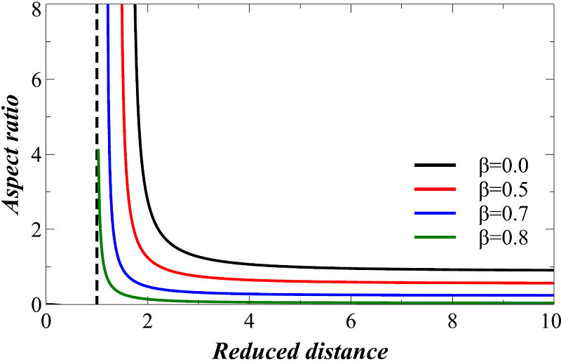
Equation Eq. (16) allows calculating the zero anisotropy curves for the tube aspect ratio (τ) as a function of the reduced distance between them for different values of the tube wall thickness β. Figure 8 shows these results.

Figure 8 Isotropic curves for the tube aspect ratio τ as a function of the reduced distance between them for different values of the tube wall thickness β

As we can see, each value of β provides a different curve. Each curve corresponds to the aspect ratio and the corresponding reduced distance for which the effective anisotropy vanishes. Points above and to the right of the curve correspond to an easy axis along the tube axis (z-axis). On the contrary, those points below the curve are those with the easy axis perpendicular to the tube axis. An important property is that, as mentioned before, reducing the tube wall thickness (increasing β) reinforces the easy axis direction along the tube axis. So that above a certain value, it is no longer possible to reverse the easy axis when the aspect ratio is decreased.

A final remark is that Eq. (16) for the 2D array of tubes made of spherical particles is the same as equation Eq. (17) in [19] for the case of continuous tubes. This despite of being different systems. However, the case reported in [19] is obtained as a particular case of Eq. (12) when P 1 = 1. In this sense, the main reason why the same expression is obtained is that the spherical particles are isotropic and therefore they do not contribute to the shape anisotropy. Indeed, as seen from Eqs. (10) and (12), the only variable related to the spherical particles present in the effective anisotropy is their packing fraction P 1 which, as discussed above, only modulates the magnitude of the anisotropy without changing its behaviour.

To validate the model, we analyze selected experimental reports based on systems with affine geometrical features. The first case of interest is that of individual magnetic particles packed into, or confined to, a well defined geometry where the dipolar interaction between particles leads to an observable magnetic anisotropy. In these regards, there are two notable examples, the first one involves packing magnetic nanoparticles into cylinders, ideally as shown schematically in Fig. 1a). In a report, Pal, et al.[20], filled carbon nanotubes with small magnetic nanoparticles. In another report, Duong, et al.[5], filled cylindrical nano holes made in a polyacrylinitrile substrate with magnetite nanoparticles. In these two studies, the magnetic characterization showed an increase of both remanence and coercive field in the cylindrically confined particles with respect to the non-confined particles. This is an indication of the presence of a magnetic anisotropy. In both cases, these effects are attributed to the enhancement of the dipolar interaction between the confined particles. The other example is the work of Merk et al.[7], and Segmehl, et al.[21], who have performed the synthesis of magnetic nanoparticles within the hierarchical structure of wood. This structure is highly anisotropic with a predominant cylindrical structure as building block, similar to an array of pores aligned parallel to each other. The in-situ growth of nanoparticles from liquid solutions leads to an important fraction of the particles being fixed on the walls of the pores, leading to a tubular structure. This corresponds approximately to the situation depicted in Fig. 1a). In both studies, the analysis of the magnetic properties of the magnetic wood shows a magnetic anisotropy favoring an easy axis parallel to the symmetry axis of the tubes. This anisotropy is attributed to the dipolar interaction between particles that are confined to the tubular shape. In the context of our model, this follows from either Eqs. (3) or (6), where it is clear that a finite magnetostatic anisotropy arises from the dipolar interaction between the particles. Moreover, from Eq. (3) we see that the magnitude of the resulting anisotropy is a function of the cylinder aspect ratio N z and the packing fraction P of the particles. For the more complex case of analyzing the inter-cylinder dipolar interaction, these studies do not explore experimentally these effects, although they recognize its importance.

The model is also well suited for 2D arrays of magnetic nanowires grown by electrodeposition into nanoporous templates. These are 2D arrays of circular cylinders, arranged so that their long exes are parallel to each other and distributed spatially forming a film. In this case, the geometrical features are the circular cylinder and the thin film containing the 2D array. For this system, Eq. (12) needs to be simplified by taking P 1 = 1 corresponding to ideal case of a continuous magnetic material and then, to treat the case of a homogeneous cylinder, we need to take β=0. Leaving only a dependence on the wire aspect ratio and the distance between wires, this is,

ΔNDt=121-31+4τπ-π34d21-11+4τπ (17)

This expression shows the competition between two terms: (a) the shape anisotropy which favors an easy axis parallel to the wires long axis the z-axis and (b) the dipolar interaction between wires, which due to the negative sign preceding it, favors an easy axis perpendicular to the long axis of the wires. The effective anisotropy of the system, in the absence of other anisotropy contributions, is the result of this competition. In this sense, a well known effect observed in arrays of NWs is the rotation of the easy axis from parallel to perpendicular to the long axis of the wires when the dipolar interaction overcomes the shape anisotropy [22, 23]. For the case of an array of continuous cylindrical NWs, the expression defining the easy axis rotation is given by Eq. (16) for β=0. In this case, it only depends on the interwire distance and the aspect ratio of the wires. As mentioned above, this leads to a curve defining the limit where the system is isotropic, this is, where the shape anisotropy of the single wire and the dipolar interaction cancel out and the effective anisotropy of the system is zero.

This effect can be analyzed using the model and comparing it with reported experimental results where the easy axis is shown to rotate as a function of either the distance between wires or their aspect ratio. To this end, we have selected data for Ni [24, 25, 26] and NiFe [27] NWs in order to avoid other materials that can have other magnetic anisotropy contributions.

Figure 9a) shows the easy axis diagram as a function of the aspect ratio and the inverse of the reduced distance. The continuous curve corresponds to Eq. (16) for β=0. The horizontal dashed line at 1/d = 0.606 corresponds to the distance for the critical packing fraction of P2=1/3 in an hexagonal array at which the easy axis rotates for the limiting case of infinitely tall nanowires [23]. Notice that this is the value at which the continuous curve tends asymptotically.
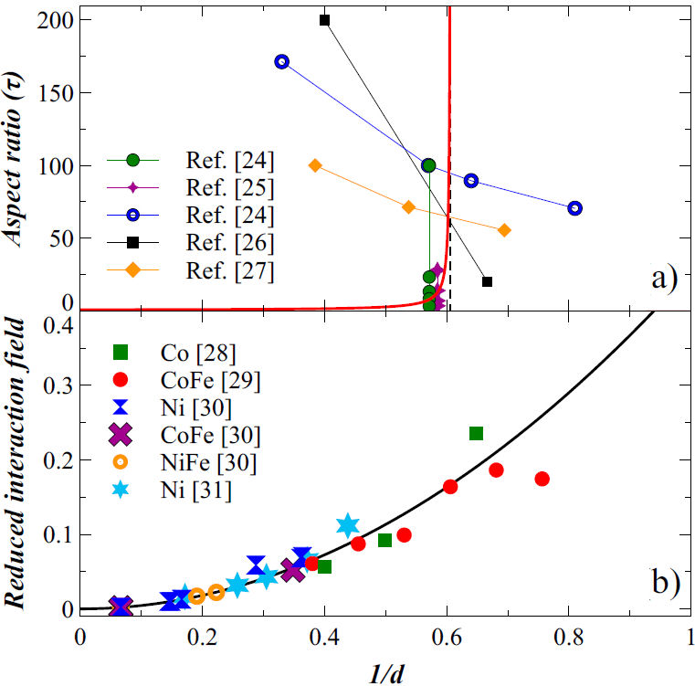
Figure 9. a) Effective anisotropy diagram for an array of nanowires as a function of the wire aspect ratio τ and the inverse reduced distance 1/d. The continuous line corresponds to the model, Eq. (17). The horizontal dashed line at 1/d = 0.606 corresponds to the distance for the critical packing fraction of P 2 = 1/3 in an hexagonal array. The data points correspond to examples of Ni [24- 26] and NiFe [27] NWs. (b) Axial component of the reduced interaction field calculated from the model (continuous line) and compared to experimental results reported for arrays of very tall nanowires [28- 31]

In this diagram, the region above and to the left side of the curve, corresponds to an easy axis parallel to the long axis of the wires. The region below and to the right of the curve, corresponds to the case where the easy axis is perpendicular to the long axis of the wires.

Consider first the experimental data for the case when the aspect ratio is varied while keeping constant the distance between wires [24, 25]. As seen in the figure, the easy axis rotates from parallel to perpendicular to the cylinder axis when the aspect ratio is reduced. Moreover, as seen from the two series of data shown in the figure, the aspect ratio at which the transition takes place is lower for larger interwire distance (1/d0). The easy axis rotation is conditioned by the wires having an easy axis parallel to the symmetry axis. For a single, non-interacting, cylinder this requires an aspect ratio larger than 0.91, since at this point the system is isotropic. Wires with aspect ratios larger but close to the critical value require a small interaction field to reverse the easy axis. As the wire aspect ratio increases, the distance between wires required to reverse the easy axis needs to be reduced (1/d increases) in order to increase the strength of the interaction field. The largest value of the shape anisotropy for the circular cylinder is attained when the aspect ratio is very large. In this case, as mentioned before, the easy axis rotates when the packing fraction is larger than 1/3. This is seen in Fig. 9a) for the data corresponding to those series of samples where the packing fraction is larger than 1/3 [24, 26, 27]. Furthermore, we can see that the easy axis rotation takes place at different aspect ratio values. The predictions of the model are in excellent agreement with the experimental results.

The other measurements that can be compared with the model are those of the axial component of the dipolar interaction field. To compare the model with available experimental results on arrays of tall NWs, we have taken the date obtained using FORC diagrams for Co (M S = 1400 emu/cm3) [28] and CoFe (M S =1991.5 emu/cm3) [29], as well as those obtained using remanence curves in Ni (M S =485 emu/cm3), NiFe (M S =788 emu/cm3) and CoFe (M S =1900 emu/cm3) NWs with diameters of 71 nm and below [30]. In addition, we have extracted the data obtained from the width of the switching field distribution (SFD) for Ni NWs [31]. To obtain the value of the interaction field from the width of the SFD we assume that the reported width w is the sum of the constant intrinsic width w0 and the shearing due to the interaction field Hint(d), this is, w=w0+Hint(d). By interpolating the data for infinite separation between NWs (Hint=0), we obtain w0 so that Hint(d)=w-w0.

The values reported in these studies correspond to the interaction term of the axial component of the interaction field [13], so to convert these values to dimensionless effective field, we have divided their magnitude by 4πMs (CGS) or μ0Ms (MKS), using the values of M S mentioned above. Moreover, Eq. (17) is the total effective anisotropy field, so to obtain the axial component, we have to divide the second term by 3 [13]. The axial component of the interaction field is given by the second term in Eq. (17), which for infinitely tall NWs, requires taking τ. By doing so, and using the inverse of the reduced distance, we can compare a single interaction curve for all the experimental points as shown in 9b). Here, the continuous line corresponds to the model while the points correspond to the experimental data. As seen in the figure, the entire data set shows a very good agreement with the model.

4 Conclusions

A simple mean field model has been presented to describe magnetostatic effects in assemblies made of isotropic spherical particles. For a two dimensional array of cylinder shaped assembly of packed spherical particles we derive approximate analytical expressions for the effective magnetic anisotropy. We find that in such particle assemblies, the shapes of the volumes that contain the particles lead to a magnetic anisotropy related to the dipolar interaction despite the fact that the particles in the assembly are isotropic. We have analyzed the main limiting cases for the anisotropy of a single tubular structure containing the particles as well as the 2D array of tubular assemblies, finding for each case the expected results. Since the expressions are analytical it is simple to derive the corresponding curves of the anisotropy as a function of the geometrical parameters of the system. The results compare well with results reported in other studies.

Acknowledgements

This work was partly supported by CONACYT project CB-286626

References

[1] E. A. Périgo, et al., Past, present, and future of soft magnetic composites, Appl. Phys. Rev. 5 (2018) 031301, https://doi.org/10.1063/1.5027045. [ Links ]

[2] O. Gutfleisch, et al., Magnetic Materials and Devices for the 21st Century: Stronger, Lighter, and More Energy Efficient, Adv. Mater. 23 (2011) 821, https://doi.org/10.1002/adma.201002180. [ Links ]

[3] J. M. Silveyra, et al., Soft magnetic materials for a sustainable and electrified world, Science 362 (2018) eaao0195, https://doi.org/10.1126/science.aao0195. [ Links ]

[4] P. S. Normile, et al., Demagnetization effects in dense nanoparticle assemblies, Applied Physics Letters 109 (2016) 152404, https://doi.org/10.1063/1.4964517. [ Links ]

[5] B. Duong, et al., Enhanced Magnetism in Highly Ordered Magnetite Nanoparticle-Filled Nanohole Arrays, Small 10 (2014) 2840, https://doi.org/10.1002/smll.201303809. [ Links ]

[6] Q. Li, et al., Enhanced magnetic performance of aligned wires assembled from nanoparticles: from nanoscale to macroscale, R. Soc. Open Sci. 7 (2020) 191656, https://doi.org/10.1098/rsos.191656. [ Links ]

[7] V. Merk, et al., Hybrid Wood Materials with Magnetic Anisotropy Dictated by the Hierarchical Cell Structure, ACS Appl. Mater. Interfaces 6 (2014) 9760, https://doi.org/10.1021/am5021793. [ Links ]

[8] K. N. Al-Milaji , et al., Inkjet Printing of Magnetic Particles Toward Anisotropic Magnetic Properties, Sci. Rep. 9 (2019) 1, https://doi.org/10.1038/s41598-019-52699-0. [ Links ]

[9] K. Deng, et al., Self-assembly of anisotropic nanoparticles into functional superstructures, Chem. Soc. Rev. 49 (2020) 6002, https://doi.org/10.1039/D0CS00541J. [ Links ]

[10] H. Gavilán, et al., How size, shape and assembly of magnetic nanoparticles give rise to different hyperthermia scenarios, Nanoscale 13 (2021) 15631, https://doi.org/10.1039/D1NR03484G. [ Links ]

[11] E. H. Sánchez, et al., Crossover From Individual to Collective Magnetism in Dense Nanoparticle Systems: Local Anisotropy Versus Dipolar Interactions, Small 18 (2022) 2106762, https://doi.org/10.1002/smll.202106762. [ Links ]

[12] S. Singh, Y. Mollet, and J. Gyselinck, Numerical Modeling of the Soft Magnetic Composite Material, In 2019 Electric Vehicles International Conference (EV), pp. 1-5 (IEEE, 2019), https://doi.org/10.1109/EV.2019.8894284. [ Links ]

[13] J. M. Martinez-Huerta et al., Configuration dependent demagnetizing field in assemblies of interacting magnetic particles, Journal of Physics: Condensed Matter 25 (2013) 226003, https://doi.org/10.1088/0953-8984/25/22/226003 [ Links ]

[14] D. A. Weitz, Packing in the Spheres, Science 303 (2004) 968, https://doi.org/10.1126/science.1094581. [ Links ]

[15] S. Li et al., Maximum packing densities of basic 3D objects, Chin. Sci. Bull. 55 (2010) 114, https://doi.org/10.1007/s11434-009-0650-0. [ Links ]

[16] B. Nam, J. Kim, and K. Ki Hyeon, Analysis of effective permeability behaviors of magnetic hollow fibers filled in composite, Journal of Applied Physics 111 (2012) 07E347, https://doi.org/10.1063/1. 3679579. [ Links ]

[17] M. Sato and Y. Ishii, Simple and approximate expressions of demagnetizing factors of uniformly magnetized rectangular rod and cylinder, Journal of Applied Physics 66 (1989) 983, https://doi.org/10.1063/1.343481. [ Links ]

[18] Y. Velázquez-Galván et al., Dipolar interaction in arrays of magnetic nanotubes, Journal of Physics: Condensed Matter 26 (2013) 026001, https://doi.org/10.1088/0953-8984/26/2/026001. [ Links ]

[19] Y. Velázquez-Galván and A. Encinas, Analytical magnetostatic model for 2D arrays of interacting magnetic nanowires and nanotubes, Physical Chemistry Chemical Physics 22 (2020) 13320, https://doi.org/10.1039/D0CP00808G. [ Links ]

[20] S. Pal, et al., Carbon nanostraws: nanotubes filled with superparamagnetic nanoparticles, Nanotechnology 20 (2009) 485604, https://doi.org/10.1088/0957-4484/20/48/485604. [ Links ]

[21] J. S. Segmehl, et al., Magnetic wood by in situ synthesis of iron oxide nanoparticles via a microwave-assisted route, J. Mater. Chem. C 6 (2018) 3395, https://doi.org/10.1039/C7TC05849G. [ Links ]

[22] G. J. Strijkers, et al., Structure and magnetization of arrays of electrodeposited Co wires in anodic alumina, J. Appl. Phys. 86 (1999) 5141, https://doi.org/10.1063/1.371490. [ Links ]

[23] A. Encinas-Oropesa, et al., Dipolar interactions in arrays of nickel nanowires studied by ferromagnetic resonance, Phys. Rev. B 63 (2001) 104415, https://doi.org/10.1103/PhysRevB.63.104415. [ Links ]

[24] G. Kartopu, et al., Size effects and origin of easy-axis in nickel nanowire arrays, J. Appl. Phys. 109 (2011) 033909, https://doi.org/10.1063/1.3531565. [ Links ]

[25] B. Das, et al., Effect of aspect ratio on the magnetic properties of nickel nanowires, J. Appl. Phys. 103 (2008) 013908, https://doi.org/10.1063/1.2828026. [ Links ]

[26] S. Khalid, R. Sharif, and Z. H. Shah, TAILORING OF MAGNETIC EASY AXIS OF NICKEL NANOWIRES BY VARYING DIAMETER, Surf. Rev. Lett. 23 (2016) 1650024, https://doi.org/10.1142/S0218625X16500244. [ Links ]

[27] E. V. Tartakovskaya, M. Pardavi-Horvath, and M. Vázquez, Configurational spin reorientation phase transition in magnetic nanowire arrays, J. Magn. Magn. Mater. 322 (2010) 743, https://doi.org/10.1016/j.jmmm.2009.10.052. [ Links ]

[28] M. P. Proenca et al., Co nanostructures in ordered templates: comparative FORC analysis, Nanotechnology 24 (2013) 475703, https://doi.org/10.1088/0957-4484/24/47/475703. [ Links ]

[29] S. Alikhanzadeh-Arani, M. Almasi-Kashi, and A. Ramazani, Magnetic characterization of FeCo nanowire arrays by firstorder reversal curves, Curr. Appl. Phys. 13 (2013) 664, https://doi.org/10.1016/j.cap.2012.10.014. [ Links ]

[30] Y. G. Velázquez, et al., Relation of the average interaction field with the coercive and interaction field distributions in First order reversal curve diagrams of nanowire arrays, Sci. Rep. 10 (2020) 1, https://doi.org/10.1038/s41598-020-78279-1. [ Links ]

[31] S. Da Col, et al., Reduction of magnetostatic interactions in self-organized arrays of nickel nanowires using atomic layer deposition, Appl. Phys. Lett. 98 (2011) 112501, https://doi.org/10.1063/1.3562963. [ Links ]

Received: December 03, 2022; Accepted: February 13, 2023

Creative Commons License This is an open-access article distributed under the terms of the Creative Commons Attribution License