


 nueva página del texto (beta)
 Inglés (pdf)
 Artículo en XML
 Referencias del artículo
 Enviar artículo por email
 Citado por SciELO
  Similares en
SciELO
Similares en
SciELO 
 Permalink
1 Introduction
The technological advances of the last two decades have made the development of an autonomous car a reality. Advances in the fields of engineering and science have enabled significant car manufacturing companies to develop their prototype autonomous cars for sale in the coming decades.
Through the development of artificial intelligence algorithms, autonomous cars are a visible reality [3]. Some of the tasks involved in an autonomous car are the detection of the road, to keep or change lanes, as well as the detection of obstacles used to overtake. In [6], the authors show that overtaking is an even more difficult problem compared to maintaining or changing lanes since it is a composite of consecutive maneuvers: lane change, overtake, and then lane change; which are coordinated.
In this work, we propose a method for an autonomous car to perform overtaking maneuvers. Our proposal consists of a high-level control policy based on object tracking using Single Shot Detector (SSD) [5]. The aim is to detect a car in front of our autonomous vehicle, which we call an obstacle car. The detection indicates the policy to drive the vehicle forward and calculates the distance to the obstacle car. For the latter, the laser scanner sensor was used. Once the obstacle car is at a specific distance, a maneuver is made for the autonomous car to avoid the obstacle car, overtake it and then get into the lane using a PID controller.
To carry out this work, we simulated an environment in Gazebo, running on the Robotic Operating Systems (ROS). We used the autonomous car model developed by [7], was used in our simulations. We evaluate the quality of overtaking by comparing it in different scenarios, changing the obstacle to overtake.
To present our work, this paper has been organized as follows: section 2 describes the approaches in this field; section 3 provides the methodology; section 4 presents our experiments and results; the last section discusses our conclusions and future work.
2 Related Work
One of the significant challenges is to get greater safety when operating autonomous vehicles to avoid traffic accidents. For this, many approaches have been proposed, one of these is the overtaking and tracking detection for vehicles [11] by selecting the right way according to the environmental conditions and avoid traffic accidents.
In [1], the authors proposed a collision detection model where prediction considered uncertainties originating from the measurements and the possible behaviors of other traffic participants. The predictions were based on stochastic systems and how they influenced decision making to drive the autonomous car.
On the other hand, Petrov and Nashashibi [6] presented a mathematical model and adaptive controller for an autonomous vehicle overtaking maneuver. Their approach is to assign three phases to the vehicle overtaking problem: 1) The overtaken vehicle is moving along a rectilinear route, 2) The linear velocity of the overtaken vehicle is unknown, 3) The available information for feedback control is the relative inter-vehicle position and orientation. In each case, the position, orientation, and speed parameters of the vehicle are used.
Another solution is trajectory planning; the authors in [2] presented a method based on a polynomial function, minimizing overtaking energy consumption according to the road condition and vehicle state. Through the trajectory re-planning algorithm, the local desired trajectory information, which satisfies the constraints of the dynamics and kinematics of the vehicle, is dynamically programmed according to the information of the constraint conditions of the vehicle.
In contrast to conventional path tracking methods, the authors in [14] presented a solution using PID control and three neural layers: the perception and processing layer, the control layer, and the decision layer. This approach depends on the information provided by the RGB camera, radar, and GPS. Motivated by this, we propose a method using deep learning and a laser sensor to perform the overtaking task.
3 Methodology
We proposed an algorithm to perform overtaking tasks using deep learning combined with a laser sensor. For this, we use the AutoModelCar model developed by ITAM [4] in the Gazebo [10] simulator running on ROS (Robot Operating System) [8]. The AutoModelCar provides data from an RGB camera, depth camera, laser scanner, and an Inertial Measurement Unit (IMU). Also, ROS topics are available to modify the geometric position, speed model, and wheel steering [4].
3.1 PID control
The derivative, integral, and proportional control is a powerful tool applied to most systems where matching an input reference is required [12].
It allows, by means of a feedback error, to obtain controlled variables. That is why, to develop the object and vehicle tracking control, this type of control has been implemented for a feedback error, to obtain controlled variables:
where, u(t), is the control function. Kp, Ki, Kd all non-negative, denote the coefficients for the proportional, integral, and derivative terms, respectively.
The model control we proposed is based on Equation 1. Where e (t) is the current error in every algorithm iteration. The error is given by the difference between the real variable and the reference variable. This reference variable is the object position in the camera image.
3.2 Vehicle Detection
We used the RGB camera to detect the vehicle by the Single Shot Detector Multi-box Detector (SDD) [5]. The SSD network combines predictions into multiple feature maps of different sizes, allowing high and low-level detections to be produced by applying convolution filters. This network is used in object detection and classification tasks, using the regression technique to obtain a bounding box.
The SSD is based on the VGG16 network [9], which fits into the general framework of object detection in deep learning, adding convolutional layers at the top of the network. These layers progressively decrease the input image’s size in a submatrix to obtain the detections at multiple scales. Each point on the feature map covers a part of the image to predict the class, and with the regression estimates, the object boundary box at the multiple locations within the image.
The SSD network provides the pixel position of the multiple objects in the image. In this case, we trained the network to identify cars. For this, we generate a dataset composed of 3054 images for training and 300 images for evaluation. This dataset was taken with an interface that allows manipulating the autonomous car movements in the Gazebo simulation environment.
The generated dataset is available at this link https://drive.google.com/drive/folders/16ep4NlrDc7k2QFNFQIwWmY7cLVtep-mH?usp=sharing.
These images were subsequently processed and tagged for training. To reduce the error in object detection, we used two classes, 1) the vehicle and 2) the background.
Fig. 2a shows the environment used to collect the images for the dataset. We select three kinds of vehicles in the simulator environment, an ambulance, a red car, and an SUV, shown in Fig. 2b. The training parameters consisted of 15 epochs and 1200 steps.
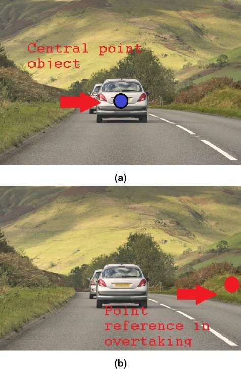
Fig. 1 In Fig. (a), reference taken in tracking mode, note reference is at the image center. In Fig. (b), reference in overtaking mode, note reference is in right side image
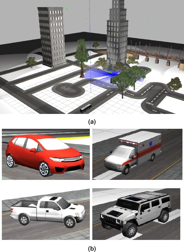
Fig. 2 Fig. (a) shows the Gazebo simulation environment used in this job and Fig. (b) shows the vehicles recognized by the SSD network
These parameters allow the network to generalizes and identify another vehicle not considered in training, and the results are shown in Fig. 10.
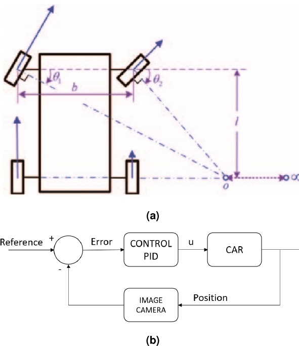
Fig. 3 In Fig. (a), Ideal Ackermann geometry is the base of car steering. Image taken from [13]. In Fig. (b), an abstract PID control proposed. PID control is proposed in order to achieve the tracking and overtaking processes
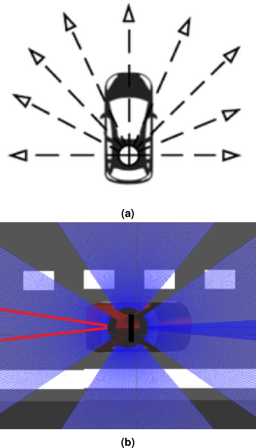
Fig. 4 Laser scanner model used in Gazebo simulator. In Fig. (b), it show used sensor to find the lane in state 6


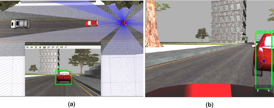
Fig. 7 Tracking and overtaking detection by SSD network. In (a), overtaking process. In (b), tracking process
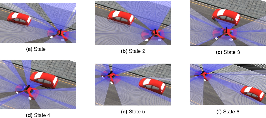
Fig. 8 Overtaking process. In every image they show a different state. In state 1, the obstacle detector and the laser are working simultaneously. In state 2, the overtaking routine is activated. In state 3, the AutoModelCar is incorporating to the left lane. In state 4, the car continues forward until the laser sensor indicates the right side is not obtruded. In state 5 and 6, the car incorporates to the right line. The video of these experiments is found in https://youtu.be/vicU3O-xRBA/uri] for revision purpose


3.3 Vehicle Tracking
For tracking, we used the SSD network to obtain the central point of the object in the image. The central point was combined with a PID control to change the steering angle at the point reference in the picture, in accordance with the Ackermann geometry, shown in Fig. 3a.
In Fig. 7, we can observe the point reference taken in overtaking. Note that this point is at the end right image, so the PID control orientates to the car to the left size obstacle trough the position that indicates the RGB camera by using the SSD network. Once the point reference is set, we propose and implement the Equation 2:
where, S represents the controlled steering in the car. L is a constant the represents neutral steering, and u(t) represents the signal control from the PID control system modeled in Equation 1:
where e(t) represents the error; this is the difference between a variable reference and an observed measure. In our tracking model, this reference point is the image center x.
The model PID control proposed is described in Figure 3b. In this control, the vehicle detector and laser sensing are working simultaneously. The detector guides the AutoModelCar into the way, and the laser sensor indicates the proximity of the obstacle. Also, to cover the blind spot of the RGB camera, we used the laser scanner, it is shown in Fig. 4a.
4 Experiments and Results
4.1 Overtaking
To perform the overtaking, we use the flow diagram shown in Fig. 5 that consist of six states described below. Furthermore, we based on the ideal overtaking curve model taken from [14], it is shown in the Fig. ??. States of algorithm:
— State 1, a PID control moves the vehicle to the left, taken as a reference point the right image size, 3b describes this process. State 1 change to state 2 when the current error in PID control is close to 0, taking as reference the right side in the image from RGB camera. Figures 1b and 7b shows this process.
— In state 2, the vehicle starts a position search given by laser scanner measurements. When this one finds the position, state 2 changes to state 3.
— In state 3, a PID control is executed to turn the vehicle to the left. The reference points are given by right lateral scanner measurements. As the PID control keeps the vehicle parallel to the object, when it is in the end, it automatically turns to the right size by a scanner flag.
— State 4 and state 5 are simple to position search based on laser scanner measurements.
— State 6, searches place to the car in the current lane. This is an achievement by calculating an error between two laser scanner symmetric measurements. These measurements are shown in figure 4b.
Fig. 8, shows the overtaking process. For this, we used static vehicles in front of our autonomous car on a straight road. We expect to obtain a smooth and symmetrical overtaking curve, as described in Fig. 9.
We implemented a series of tests with an autonomous car speed of 150 (this model does not provide specific units). In each test, we modulated several parameters to get better results in function to vehicle to overtake. The results were graphed by using the current autonomous car position published as a topic in ROS. The number of tests with adjusted parameters was 100, where 92 were successful in according to the parameters said. This represents a 92 percent probability of success.
Although this number is still quite low, it represents an important value compared with the work published by reference [14]. Fig. 10 shows the results obtained when testing the various vehicles to overtake. Ten tests were carried out on each vehicle and were plotted, as shown in the figure. It is noted that the behavior in each vehicle is similar in its ten graphical executions.
Fig. 11a shows the implementation of tracking and overtaking algorithms. In the simulator were places three ambulance models and were tracked and overtaken by the Autonomous car. In the same way, Fig. 11b and Fig. 11c shows the behavior in Red Car and SUV models. The video of these experiments is found in https://youtu.be/vicU3O-xRBA for revision purpose.

5 Conclusions
In this work, we have presented an approach for ”the overtaking vehicle” problem by an autonomous car. An overtaking of vehicles implies a good tracking of the vehicle to be overtaken. Tracking and overtaking are tasks strongly related to each other. The importance of solving this problem lies in the safety of autonomous cars since overtaking by a machine could lead to safer driving.
The proposed algorithm in this work addresses the problem by tackling first the detection and tracking task. Such detection is used then for the overtaking maneuver. This algorithm is based on a set of states in a state machine, where each state contains a PID controller. Our approach exploits sensors onboard the vehicle, such as an RGB camera and a laser scanner sensor.
In this work, we have achieved a success rate of 92/100 tests carried out in a controlled environment. It is comparable to previous works. Similarly, our control strategy produced a smooth overtaking maneuver. This one is of most importance, as abrupt changes can cause car accidents. Furthermore, our results showed a smoother overtaking curve, compared to the job of [2]. In the Fig. 9 show their results.
In our future work, we will train a bigger dataset with more classes in order to make more robust the object identification. Currently, the laser sensor returns some noisy signals that depend on the obstacles or objects ahead of the autonomous car. For this reason, we need to implement a filtering technique in future implementations. Another possibility is to use the onboard depth camera, although the depth range is shorter than the depth sensed with the laser. A fusion of both sensors is also a possibility.

