


 nueva página del texto (beta)
 Inglés (pdf)
 Artículo en XML
 Referencias del artículo
 Enviar artículo por email
 Citado por SciELO
  Similares en
SciELO
Similares en
SciELO 
 Permalink
Introduction
A tumor is a mass of transformed cells with abnormal growth and multiplication (The Oxford English Dictionary, 2010). Tumors can be cancerous (malignant) or non-cancerous (benign) and occur when cells multiply excessively in the body. Normally, cell division and growth are tightly controlled. New cells are created to replace old ones. Cells that are damaged or are no longer needed, die to make way for healthy replacement cells. If the balance of division and cell death is altered, a tumor may form (U.S. National Library of Medicine, 2014).
Breast cancer appears as malignant tumors originating in the cells of the breast. Breast cancer occurs almost exclusively in women, but cases have been known to occur in men. Breast cancer is the second most common cancer worldwide with 1.677 million cases equivalent to 11.9 % of all cancers (Who. GLOBOCAN, 2012). In developed countries, the survival rate at 5 years for this type of cancer exceeds 80 %, while for underdeveloped countries the rate falls between 10 to 40 %, this is because developing countries often lack the facilities and personnel for an early detection of the disease (WHO, 2014).
Advances in science have yielded new alternatives for treating this type of cancer. Often, the patient has several options: chemotherapy, radiotherapy, hormone therapy and surgery, the latter is the most widely used in the treatment of breast cancer (Breast Cancer Org., 2019).
If the cancer is detected at an early stage, there are minimally invasive techniques for treatment, for example: laser photocoagulation, ultrasound, cryotherapy and hyperthermia ablation; which is divided into radiofrequency ablation (RFA) and microwave ablation (MWA) (Van et al., 2007). Additionally, these minimally invasive techniques can be applied to patients who for various reasons cannot be treated surgically (Hompes et al., 2010; Zanus et al., 2011; Simo et al., 2013; Lloyd et al., 2011; Ratanaprasatporn et al., 2013; Livraghi et al., 2012; Iannitti et al., 2007; Veltri et al., 2012; Carrafiello et al., 2014; Little et al., 2013; Wolf et al., 2012; Carrafiello et al., 2010a; 2010b; Guan et al., 2012).
The placement of a needle or a catheter directly into a tumor and the use of heat, cold, or a chemical to destroy it, is called ablation. It is more frequently used to stop the spread of cancer to the bones or the liver, although it can also be used in other places or organs. Ablation is usually employed when only a limited number of tumors are causing problems.
A common type of ablation, radiofrequency ablation (RFA), uses a needle that carries an electric current. The end of the needle is inserted into the tumor. An ultrasound or a CT (Tomography) can be used to ensure that the needle is in the right place. An electrical current that passes through the needle warms the tumor to destroy it. In general, RFA is performed while the patient is under general anesthesia (Vydra & Vrba, 2011).
Another type of ablation, called Cryoablation, uses the probe placed in the tumor to freeze it, which destroys cancer cells (Shinohara, 2007).
Other methods use heat (laser-induced interstitial thermotherapy) or alcohol to destroy cells (Society AC, 2015).
In medicine, microwaves are being used increasingly for tumor ablation. Microwaves cause the tumor to heat and burn. To achieve MWA the tissue should be heated to a temperature of 55 °C or more, however maximum temperature should not reach 100 °C, since that would cause water to evaporate changing tissue properties, several prototypes of antennas are used to accomplish that. These antennas are designed trying to make them smaller and better targeting of energy to prevent damage on healthy tissue (Bertram et al., 2006).
MWA is a promising technique for breast cancer because the energy can be focused to selectively damage carcinomas of the breast. This can be attained due to their high water content compared with a lower level of heating in the adipose and glandular tissue that have lower water content (Vargas et al., 2004; Mariya et al., 2007; Liu et al., 2018).
For breast cancer, reports of the application of this technique have been made in patients with inoperable tumors (Zhou et al., 2014), the results obtained so far are an excellent option for people suffering from this disease. The results have shown that it is a very good alternative in small tumors, since the application time is small and the results are very encouraging especially for these patients (Liu et al., 2018; Li et al., 2017).
There are several prototypes of antennas that have been reported with their associated simulations and ex vivo tissue studies, mostly in swine breast or bovine liver (Guerrero, 2014; Cavagnaro et al., 2011; McWilliams et al., 2015; Luyen et al., 2015; Karampatzakis et al., 2013), in the Table 1 a comparison of different types of antennas and their results is shown.
Table 1: Comparison of different types of antennas and their results
| Reference | Antenna type | Experiment | Results |
|---|---|---|---|
| Cavagnaro, et al., 2011 | Closed tip antenna | Bovine ex-vivo liver | Ablation zone of approx. 38 x 28 mm (Length × Diameter) with a 20 watts potency |
| McWilliams et al., 2015 | Directional antenna | Porcine muscle | Ablation radius 10 mm in forward direction and 5 mm radius in backwards direction, with a 80 watts power |
| Luyen, et al., 2015 | Helical antenna | Bovine ex-vivo liver | Ablation zone of 75 x 43 mm, with a 42 watts power |
| Karampatzakis, et al., 2013 | Slot-antenna Double slot-antenna | In-silico study | Ablation zone of 32 x 30.5 mm, with a 50 watts power |
The closed tip antenna has an outer diameter of 1.53 mm however its construction is complicate, the directional antenna has 1.194 mm outer diameter but it needs a reflector that has a diameter of 2.4 mm, the helical antenna has an outer diameter of 2.197 mm, finally the slot and double slot antennas were constructed with a diameter of 1.3 mm. Every mentioned antenna show good results, however the slot and double slot antennas are easier to construct, for these reasons a slot antenna was considered for this study.
The objective of this work is to evaluate the efficiency of two applicators with the same design, slot antenna (Cepeda et al., 2015), but different diameters, to determine the feasibility of using a thinner applicator, which facilitates puncture, since it is important to select the most suitable type of cable for microwave ablation.
Materials and methods
Slot antenna
MWA applicators are antennas, generally coated with polytetrafluoroethylene (PTFE) to minimize adhesion to the (carbonized) tissue that is exposed to ablation, normally, the applicators designs for MWA are made for treatment of liver cancer, and some of these designs can be: Dipole, Monopole and Slot.
The design chosen for the present work is a slot antenna. In MWA, the slot antenna is one of the most popular designs, it is easily made with a semi rigid coaxial cable, which is short-circuited at one end and a ring-shaped slot is cut in the outer conductor of the cable (Cepeda et al., 2015), a diagram of this design is shown in the Figure 1. In this work two slots antennas were considered, one with a diameter of 2.197 mm and the second with a diameter of 1.194.

The effective wavelength at the operation frequency in the tumor tissue was considered to select the distance between the tip of the antenna and the slot. To calculate the wavelength the equation (1) is used:
In the equation c represents the speed of light in free space (m/s), f represents the operating frequency of the generator (2.45 GHz), εr represents relative permittivity of the tumor at operating frequency (59.385) and µr represents the magnetic relative permeability (1). Using this values the wavelength obtained is 15.88 mm; but since the tissue is not homogeneous, this value can be used only as a reference. The distance between the slot and the tip is approximately one fourth of the effective wavelength.
Standing wave ratio
The standing wave ratio (SWR) is the ratio of maximum to minimum voltage signal on a transmission line (Merriam-Webster, 2019). Ideally, a transmission line should have a SWR of 1, with all the power delivered and no power reflected. To calculate the SWR the equation (2) is used:
Where Γ represents the reflection coefficient. Before starting the ablation the SWR should be measured and during the ablation test the incident and reflected powers must be monitored. This is because there is a warming called detrimental heating, which occurs along the antenna when a large portion of the energy is reflected to the signal generator instead of being delivered to the tissue. This heating can cause damage in tissue outside the treatment region, and if the SWR is too high it can damage the equipment. To measure SWR a network analyzer (E5071B ENA, Agilent Technologies, Santa Clara CA) was used, this device was also used in the measurement of the dielectric properties of the materials used for validation experiments.
In silico model
Simulations were made to observe the performance of antennas before doing experimental validation in phantom tissue. The thermal and dielectric properties of breast cancerous tumors and healthy breast tissue were obtained from the literature (Mariya et al., 2007; Lazebnik et al., 2007; Gautherie, 1980), the values used in the computer model are shown in Table 2.
Table 2: Dielectric properties of breast tumor tissue at 2.45 GHz
| Property | Breast tissue | Cancerous tissue |
|---|---|---|
| Conductivity (s/m) | 0.137 | 3.156 |
| Relative Permittivity | 5.1467 | 59.385 |
| Thermal Conductivity (W·m-1·K-1) | 0.42 | 0.50 |
The computational model was made in COMSOL Multiphysics (COMSOL Inc., Burlington MA), due to its ability to simulate the electromagnetic and thermal characteristics of the problem. COMSOL Multiphysics uses the finite element method (FEM) to solve the physical problems. The FEM is a numerical technique that can be formulated as functional minimization, it involves dividing a complex geometry into small elements for a system of partial differential equations, evaluated at nodes or edges. Nonetheless to obtain an accurate solution, appropriate initial and boundary conditions should be selected.
The simulation can be reduced to a 2D axisymmetric model, since it presents rotational symmetry, allowing a two-dimensional modeling using cylindrical coordinates, and reducing computational time. Figure 2 shows the in silico model considering an applicator inserted in a round breast carcinoma surrounded by healthy breast tissue.
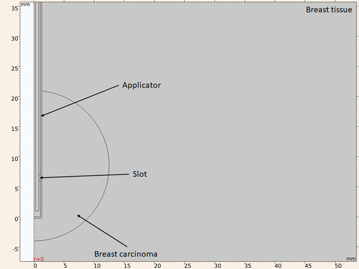
Figure 2: Model geometry considering a UT-47 applicator inserted in a round breast carcinoma surrounded by healthy breast tissue
The considered boundary conditions are: for both simulations the z axis is considered as axial symmetry, for the electromagnetic simulation all the exterior boundaries are considered as scattering boundary condition, with the only exception of the exterior boundary of the dielectric of the applicator, which is considered as port condition with and applied power of 10 W, for thermal simulation all the exterior boundaries are considered as constant temperature (25 oC). As mentioned above the FEM divides the geometry into smaller elements, this process is called meshing. The accuracy that can be obtained from any finite element analysis (FEA) depends on the used mesh. As mesh elements are made smaller the computed solution will be closer to the actual solution. However, if the mesh is excessively thin the computational time and resources needed to obtained the solution are higher. Taking this into consideration the mesh should be thin enough to obtain a valid solution, but not too much to make computational time tend to infinite. For an electromagnetic FEA the maximum element size recommended is one eighth of the effective wavelength at highest frequency. Using equation (1), considering that the maximum frequency in the study is 3.5 GHz and the highest relative permittivity is the one for the breast carcinoma (ε r =59.385), the smallest wavelength in the study is 11.11 mm, so the maximum element size shouldn’t exceed 1.38 mm. The mesh used in the computational model has a maximum element size of 1 mm and a minimum size of 0.0038 mm, under these conditions the mesh has 38638 triangular elements, 2528 edge elements, 23 vertex elements. A portion is shown in Figure 3 of the mesh used in the model.

For computational modeling it is necessary to use an equation that governs the physical behavior of the phenomenon, for the case of ablation therapies the most used equation is the Pennes bioheat equation (Ibitoye et al., 2015) that is given by:
In the equation ρ is the tissue density (kg·m-3), Cp is the specific heat capacity at constant pressure (J·kg·m-3) k represents tissue thermal conductivity (W·m-1·K-1), ρ bl is the blood density (kg·m-3), Cbl represents the specific heat capacity of the blood (J·kg-1·K-1), ωbl is the blood perfusion (kg·m-3·s-1), Tbl represents blood temperature (K) and T is the final temperature (K), Qmet is the metabolic heat generation (W·m-3), Qext is the absorbed electromagnetic energy (W·m-3). Since the experimental validation is conducted on phantom tissue blood perfusion and metabolic heat generation can be neglected. The absorbed electromagnetic energy is given by the equation:
Experimental validation
Antenna construction
Two applicators were constructed to validate the computational model with a UT-85 and UT-47 (Li et al., 2017; Guerrero, 2014) coaxial cables, with 2.197 mm and 1.194 mm diameters respectively. The two applicators have the design shown in Figure 1. To build the applicators PCB manufacturing methods are used, first a mask is placed in the coaxial cable, after that the cable is painted with acrylic paint to protect the copper from the ferric chloride (Figure 4). Once the slots are made, the outer and inner conductor are short-circuited at the tip of the applicator. Finally, a SMA connector is mounted on the other side of the applicator.

Phantom elaboration
A phantom is a physical model reproducing the electrical characteristics of interest, such as permittivity and conductivity. A phantom model should imitate dielectric properties of living tissue. Phantoms are usually made using sodium chloride (NaCl), aqueous solutions, glycerin, agar, aniline, among others, made based on NaCl solution, the most popular phantom. This is easily prepared and its components are readily and easily available. Distilled water is used and NaCl is added to adjust the conductivity without changing the permittivity with concentrations below 10 g / l. To adjust the permittivity vegetable oil is used and to achieve a homogeneous mix neutral detergent is added, finally to obtain a gelatinized phantom, agar is added, to the mix (Ortega, 2010).
To elaborate the breast phantom tridistilled water (50 ml), vegetable oil (150 ml), neutral detergent (30 ml) and agarose (4.5 g) were mixed and heated, the breast carcinoma phantom was composed of tridistilled water (100 ml), ethanol (60 ml), sodium chloride (1 g) and agarose (1.5 g) (Ortega, 2010).
The geometry utilized in the in-silico model is a spherical cancerous tumor inside a cylinder of breast tissue, to achieve this a sphere of cancerous phantom was created and once it solidified, it was inserted in a glass beaker filled with breast phantom not yet solidified, Figure 5.

SWR measurement
To evaluate the efficiency of the applicators (constructed with 2.2 mm and 1.2 mm diameters cables), the SWR was measured with a network analyzer (E5071B ENA, Agilent Technologies, Santa Clara CA), when the applicator was inserted on the phantom. This measure was later compared with the SWR obtained in the in-silico model.
Results
SWR
Three conditions were considered for the in-silico model and measurement of the SWR, when the applicator is inserted in healthy breast tissue when it is inserted into breast tumor tissue and when is inserted into a spherical tumor surrounded by healthy breast tissue.
For the first consideration (applicator inserted in healthy breast tissue) the SWR for the applicator constructed with a UT-47 microcoaxial cable (1.2 mm diameter) is 1.72 in the experimental validation while the in-silico model results show a SWR of 2.18, both of them at the operation frequency of 2.45 GHz, Figure 6 shows the SWR graph in the 2 to 3.5 GHz interval.
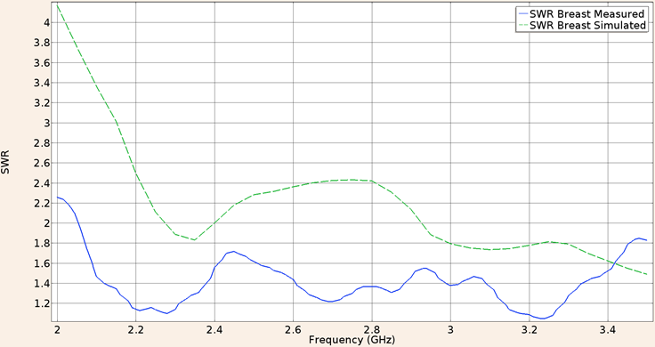
Figure 6: Measured (solid line) and simulated (dashed line) SWR for the UT-47 microcoaxial cable applicator into breast phantom tissue, in the 2 to 3.5 GHz interval
Considering the applicator constructed with a UT-85 microcoaxial cable (2.2 mm diameter) inserted in healthy breast tissue the SWR measured in the validation experiment was 1.50 while the in-silico value was 1.68 both for a 2.45 GHz frequency. Figure 7 shows the SWR graph in the 2 to 3.5 GHz interval.
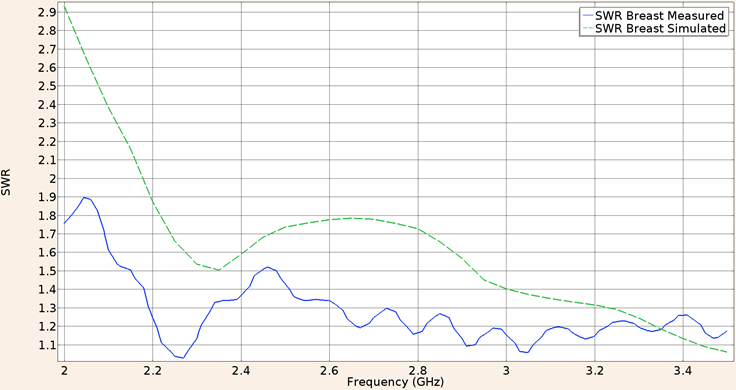
Figure 7: Measured (solid line) and simulated (dashed line) SWR for the UT-85 microcoaxial cable applicator into breast phantom tissue, in the 2 to 3.5 GHz interval
For the second consideration (applicator inserted into breast tumor phantom), the SWR obtain in the validation experiment using the UT-47 applicator was 1.61, while the in-silico result was 1.18. The Figure 8 shows the SWR graph for a frequency of 2 GHz to 3.5 GHz.
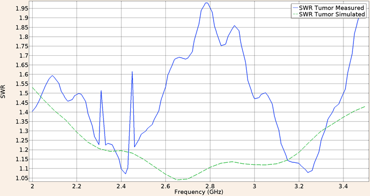
Figure 8: Measured (solid line) and simulated (dashed line) SWR for the UT-47 microcoaxial cable applicator into breast cancer phantom tissue, in the 2 to 3.5 GHz interval
For the second consideration (applicator inserted into breast tumor phantom), the SWR obtain in the validation experiment using the UT-85 applicator was 1.23, while the in-silico result was 1.54. The Figure 9 shows the SWR graph for a frequency of 2 GHz to 3.5 GHz.
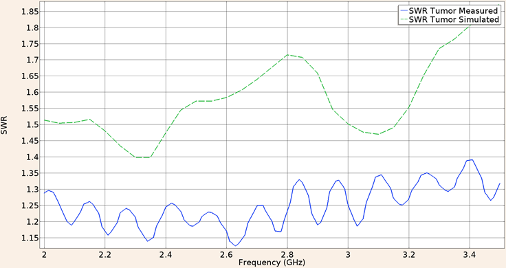
Figure 9: Measured (solid line) and simulated (dashed line) SWR for the UT-85 microcoaxial cable applicator into breast cancer phantom tissue, in the 2 to 3.5 GHz interval
Finally when the UT-47 applicator was inserted in a spherical tumor phantom surrounded by breast phantom, the SWR at a frequency of 2.45 GHz for the in-silico model was 1.17 while the measured in the validation experiment was 1.35. Figure 10 shows the SWR graph in the 2 to 3.5 GHz interval.
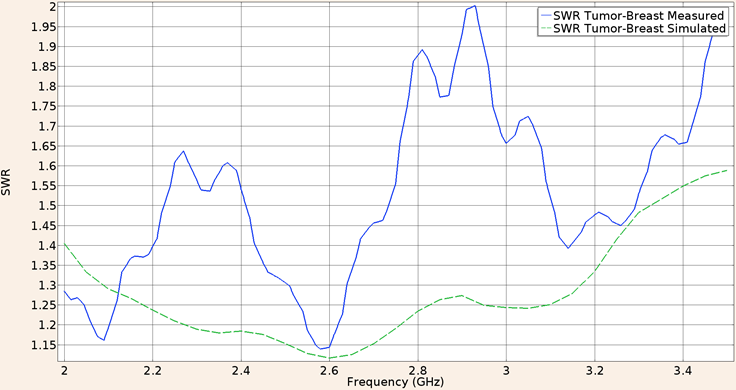
Figure 10: Measured (solid line) and simulated (dashed line) SWR for the UT-47 microcoaxial cable applicator in tumor phantom surrounded by breast phantom, in the 2 to 3.5 GHz interval
And for the applicator constructed with the UT-85 inserted in a spherical tumor phantom surrounded by breast phantom, the SWR at a frequency of 2.45 GHz for the in-silico model was 1.63 and the measured in the validation experiment was the same. Figure 11 shows the SWR graph in the 2 to 3.5 GHz interval.
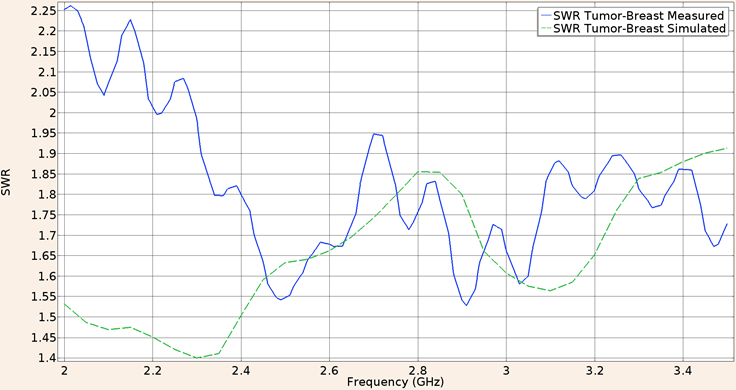
Figure 11: Measured (solid line) and simulated (dashed line) SWR for the UT-85 microcoaxial cable applicator in tumor phantom surrounded by breast phantom, in the 2 to 3.5 GHz interval
Finally a comparative of the SWR measured for both applicators is shown in Figure 12, the minimum value of SWR for the applicator constructed with UT-47 coaxial cable is 1.14 at a frequency of 2.58 GHz, and the minimum value for the UT-85 applicator is 1.52 at a frequency of 2.91 GHz.

Heating patterns
The heat patrons for the three proposed conditions were only obtained in the in-silico model considering an applied power of 10 W for the port boundary of the applicator, for the first condition, applicator inserted into breast phantom, the maximum temperature achieved by the UT-47 applicator was 118 °C, the maximum ablation radius was 9.5 mm. Figure 13 shows the heating pattern for these conditions. Notice that maximum temperature was above 100 °C, however since the effect of blood perfusion was not considered in the simulation, it is expected that the maximum temperature reduces when the blood perfusion effect is present.
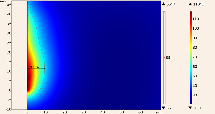
Figure 13: Heating pattern obtained in the simulation considering the UT-47 applicator inserted into breast tissue
Similarly Figure 14 shows the heating pattern for the in-silico model considering the UT-85 applicator inserted into breast tissue, notice that the maximum temperature reached was lower (101 °C) for this applicator, and also the 55 °C isothermal contour was slightly smaller (0.1 mm in diameter and 5 mm in height).
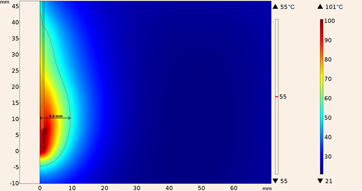
Figure 14: Heating pattern obtained in the simulation considering the UT-85 applicator inserted into breast tissue
For the second consideration (applicator inserted in tumor tissue), the heating pattern for the UT-47 applicator is shown in Figure 15, the maximum ablation radius was 11.7 mm and the temperature reached was 155 °C, the shape of the lesion was more spherical than the one obtained with the applicator inserted into breast tissue.
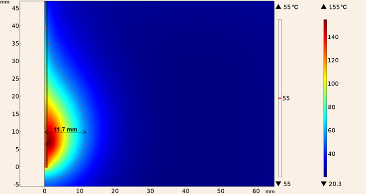
Figure 15: Heating pattern obtained in the simulation considering the UT-47 applicator inserted in tumor tissue
Whereas the maximum temperature obtained considering the UT-85 applicator inserted in tumor tissue was 124 °C and the maximum ablation radius was 11.1 mm, the heating pattern is shown in Figure 16.
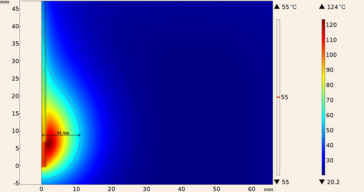
Figure 16: Heating pattern obtained in the simulation considering the UT-85 applicator inserted in tumor tissue
In addition, the heating pattern of UT-47 applicator when it was inserted in a spherical tumor surrounded by breast tissue is shown in Figure 17, the maximum temperature reached was 161 °C with a maximum ablation radius of 12.9 mm, however total tumor ablation was not achieved.

Figure 17: Heating pattern obtained in the simulation considering the UT-47 applicator inserted in a spherical tumor surrounded by breast tissue
Finally, the heating pattern of UT-85 applicator when it was inserted in a spherical tumor surrounded by breast tissue is shown in Figure 18, the maximum temperature was 128 °C, and the maximum ablation radius was 12.3 mm.
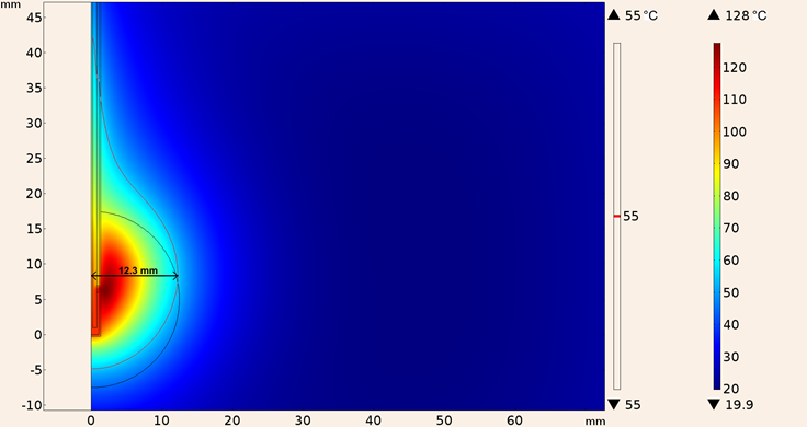
Figure 18: Heating pattern obtained in the simulation considering the UT-85 applicator inserted in a spherical tumor surrounded by breast tissue
In Table 3 the SWR, maximum ablation radius and maximum temperature for both applicators in the three experimental setup are shown. Notice that for the clinical situation, tumor surrounded by breast tissue, the results for the UT-47 applicator are better, since it has a superior coupling, a bigger ablation radius and a higher maximum temperature.
Table 3: SWR, maximum ablation radius and maximum temperature for UT-85 and UT-47 applicators in breast tissue, cancer tissue and cancer surrounded by breast tissue
| UT-85 | UT-47 | ||
|---|---|---|---|
| Brest Tissue | SWR (In silico/validation) | 1.68/1.5 | 2.18/1.72 |
| Ablation Radius (mm) | 9.4 | 9.5 | |
| Max temperature (°C) | 101 | 118 | |
| Cancer Tissue | SWR (In silico/validation) | 1.54/1.23 | 1.18/1.61 |
| Ablation Radius (mm) | 11.1 | 11.7 | |
| Max temperature (°C) | 124 | 155 | |
| Breast-Cancer Tissue | SWR (In silico/validation) | 1.63/1.63 | 1.17/1.35 |
| Ablation Radius (mm) | 12.3 | 12.9 | |
| Max temperature (°C) | 128 | 161 |
Conclusions
As an alternative to surgery, microwave ablation therapy is a promising technique to treat breast cancer in an early stage. The purpose of this work was to determine the viability of building thinner applicators, in order to reduce the size of the incision necessary to use this technique. The analyzed results were: temperature reached, size of lesion, and SWR, of in-silico and physical models (tumor and breast phantom).
The results obtained in the in-silico model show that the ablation temperatures are reached, in other words, temperature higher than 55 °C, it is important to notice that in all three considerations the temperature reached by the UT-47 applicator was superior to the obtained with the UT-85 applicator, however this is not necessarily good since temperatures above 100 °C can change tissue properties drastically, thus decoupling the applicator. Nonetheless since blood perfusion was not considered in the simulation these temperatures may be lower in a clinical situation. The coupling of the designed antennas was predicted using computer simulation. In general, both applicators show good coupling (SWR lower than 1.8). UT-47 applicator had higher value of SWR in the model where it was inserted into breast tissue compared to the SWR obtained by the UT-85 applicator, 2.18 and 1.68 respectively, but the UT-47 applicator has lower SWR in the other two computational models. The difference between simulations an the validation experiments does not present a problems since the reflected power for the UT-47 in the simulation in which the antenna is inserted in tumor tissue surrounded by breast tissue was 0.6 % while in the validation experiment was 2.2 %, on the other hand the results for the antenna constructed with the UT-85 in the same condition were the identical in the simulation and the validation experiment, 5.7 % of reflected power, this lead us to believe that the computational model is appropriated to predict the reflected power. The differences between the in-silico model and the validation experiments could be explained by the fact that the dielectric properties of tissue were not as constant and homogenous as they were considered for the simulation. It is also important to notice that in the simulations where the applicators were inserted into a spherical tumor surrounded by breast tissue, total ablation was not achieved, though it may be obtained by increasing the applied power.
Unquestionably the mechanical properties of the applicators should be considered, and the thinner applicator (UT-47) is extremely fragile, since it presented difficulties to be inserted in the phantoms, because it tended to bend easily. While the UT-85 applicator did not presented this problem And this must be considered with great importance when selecting the most suitable cable in microwave ablation.
Lastly it is still necessary to validate these results in ex-vivo breast cancer tissue and in-vivo laboratory tests before concluding if it is feasible to use these applicators for breast cancer treatment.

