


 nueva página del texto (beta)
 Inglés (pdf)
 Artículo en XML
 Referencias del artículo
 Enviar artículo por email
 Citado por SciELO
  Similares en
SciELO
Similares en
SciELO 
 Permalink
1. Introduction
Power efficiency in solar cells strongly depends on the materials used for the substrates, their electrical conductivity, mobility, tunable structure and the size and orientation of the crystals (Guo et al., 2018). Presently, different invasive techniques can modify the size and orientation of crystals to reduce the electrical resistivity (Cheng et al., 2010; Gabb, et al., 1986; Kaga et al., 2007; Ohyama et al., 1998). With a certain degree of success. Recent studies suggest that the use of high magnetic fields could also induce a preferable orientation on crystal structures during the precipitation phase (Asai et al., 2003; Hansen & Bernier, 1972; Morikawa et al., 1998) providing a non-invasive method. To determine the magnetic field magnitude, time of exposure, and field quality, we must conduct a series of experimental studies for each proposed substrate. For this, we face a technological challenge: we require a device capable of providing a controlled temperature environment (some substrates require temperature in the range of 25 °C -200°C), and at the same time, the capability of producing high magnetic fields (7 T to 10 T) during the crystal growth phase. To generate a magnetic field greater than 2 T, we require superconducting technology.
In commercial superconducting solenoids (Gabriel & Tan, 1988; Kunzler et al., 1961; Yamamoto et al., 1988) both the superconducting windings and the sample, experience cryogenic temperatures, this is against the temperature requirement of the sample; requiring developing non-existing technology.
The Applied Superconductivity lab at Universidad de Guanajuato has endeavored to develop a novel approach of a superconducting 7 Tesla solenoid that incorporates a thermally isolated chamber for magnetic stimulation of samples. The chamber integrates a heating system to stimulate the crystal structures thermally. The proposed design makes use of an adapted version of the cable-in-conduit (CIC) technology developed by McIntyre et al. (2019). Block-coil high-field dipoles using superconducting cable-in-conduit, (McIntyre et al., 2018) Block-coil high-field dipoles using superconducting cable-in-conduit, (Breitschopf et al., 2020). The solenoid windings form around a thermally insulated narrow chamber (3 cm wide x 60 cm high).
An optimization process for CIC conductor’s number and position helped expand the magnetic field to a uniform region of 3 am wide and 10 cm height while reducing the amount of required CIC. The optimized version provides enough space for inserting the sample and requires instrumentation (heating circuit and thermometers) see Figure 1.
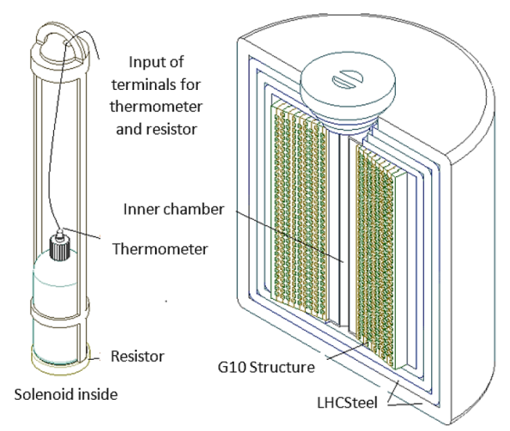
Figure 1 Figure at left shows the solenoid insert, positioning the sample in the magnetic field’s uniform region. Thermometers and resistors monitor the temperature of the sample. The figure at right shows a side view of the compact high-field solenoid, using an adapted version of a double-layer NbTi cable-in-conduit. The superconducting windings surround a thermally isolated narrow chamber.
We design the superconducting solenoid to operate at a magnetic field in the range of 6T -7T using NbTi double-layer CIC conductors, producing a large region with a homogenous magnetic field for sample testing. The homogenous region’s magnetics field for commercially available superconducting solenoids is typically limited to about 3 cm in height.
Our design offers a uniform area of 3 cm wide and 10 cm height 3 x of existing commercial technology.
In this work, we present a preliminary study of the magnetic field distribution inside the solenoid, the optimization process to reduce the produce a maximum field of 7 T, and a magnetic force study a prototype superconducting cable shows the expected performance.
2. Cable in conduit (CIC) conductor
The cable-in-conduit superconducting technology developed by McIntyre et al. (Breitschopf et al., 2020) offers an efficient cryogenic alternative for superconducting applications, reducing the required amount of refrigerant and increasing the thermal stability of the superconductor. One of the advantages of the CIC superconductors. One of the advantages of the CIC superconductors lies within the high-strength outer tube. The latter be haves as a cryogenic vessel, reducing the extra-cooling and increasing the mechanical stability of the superconductor. McIntyre et al. showed that with the help of mechanical benders, the CIC cables could be bent in a small bending radius and form complex structures (Chavez et al., 2019). These two properties are desirable in designing a compact superconducting solenoid with a thermally isolated chamber.
The CIC cabled used in the solenoid is based on the double layer CIC conductor presented by Brietschopf et al. (2020). We could increase the thermal insulation capabilities by adding two layers (125 μm thick) of Coolcat 4k superinsulation (Hirschl et al., 2006) (Figure 2. Image item 5), one after the high-strength foil, and one at the outside surface of the outer tube. The multi-layered aluminum-polyester stack acts as a low absorptance helium vessel laminate for the CuNi90/10 outer tube in the CIC conductor.
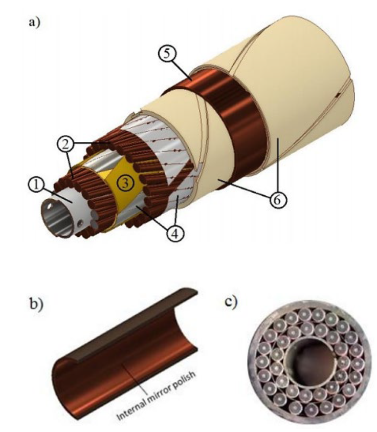
Figure 2 Side view of a double-layer CIC superconductor that incorporates thermal insulation. Figure a) show the components by layers: 1.-The high strength perforated inner tube, 2.- The first and second layers of superconductors (1.2 mm outer diameter NbTi). The first layer has 15 wires and the second layer has 21 wires. Both layers were cabled, matching a 2-inch bend radius. 3.- The protective layers between the inner and outer layer of superconductors. 4.- Protective foil for the second layer of superconductors; 5.-Coolcat superinsulation, 6.- High strength outer tube. Figure b) shows a mid-plane dissection of the outer tube. The tube will be polished internally using an aqueous hydrogen peroxide solution to suppress thermal reflection. On c) a cross-section cut of a double-layer prototype, showing 15 NbTi wires 1.2 mm diameter in the first layer, and 21 on the second layer.
Figure 2 shows a side view of the double-layer CIC conductor and its components, including the two improvements, the extra layers of superinsulation, and the chemical polishing at the interior face of the outer tube. Based on the technology limitations of the Applied Superconductivity lab, we have opted to partner with Accelerator Technology Corp to produce the double-layer CIC conductor with the extra layers of superinsulation.
The superconducting wire used in the double layer is a Hi-Ho (High homogeneity) NbTi wire, manufactured accordingly to the wire specifications of the Superconducting Super Collider (SSC) magnets (Kanithi et al., 1989). The superconducting wire is 1.2 mm in diameter with a copper to superconductor ratio 1.5 and an RRR value of 120:1. The superconductor has 7400 filaments in the matrix with 8.9 microns in diameter each.
To determine if the manufacturing process of the CIC in dudes a current degradation on the superconducting wire, a critical current vs. applied field test was carried out at the Superconducting lab at Ohio State University (OSU). We removed the outer tube of a prototype version of the CIC for the test, exposing the superconductors. Four wires were extracted from the CIC and sent to OSU with two virgin samples (wires taken directly from the spool) for the Ic test.
An increasing current in an increasing magnetic field pushed the superconducting wires to quench, as shown in Figure 3. The red dotted line represents the theoretical specifications provided by the manufacturing company of the NbTi superconducting wires, Supercon Inc (Supercon, 2021). The rest of the points show the experimental measurements over the extracted (S1, S2, S3, and S4) and virgin (Witness S1 and S2) samples.
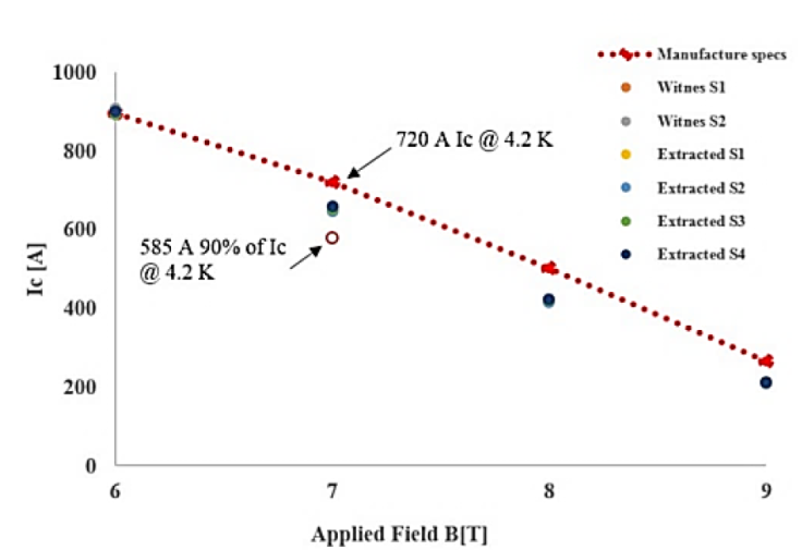
Figure 3 Critical current vs. applied field for NbTi superconducting wires, extracted from a 2-layer CIC. Figure 3 shows ana Ic test conducted over six wires, four removed from a prototype of a 2-layer CIC, and two virgin wires (Witness samples) from the spool of superconductor. The experimental performance of the wires is compared with the manufacturers’ specifications. Measurement shows no current degradation; the four extracted wires perform as the witness sample, and both offer lower performance than the manufacturer’s specifications. We consider an operation current for the wires 90% (585 A) lower than the Ic value (650 A) for a field of 7 T at 4.2 K.
The performance of both the witness and extracted wires overlap, which means there is no current degradation associated with the manufacturing procedure.
Accordingly, to the manufacturer specs, at a 7 Tesla field at 4.2 K, the superconducting wire quenches at an operational current of 720 A per wire. Nevertheless, measurements over the extracted and witness wires show the wire quenching at 650 A. The superconducting wire on the 2-Layer CIC will operate at a current of 585 A per wire, with a total current per CIC of 25.6 kA at 4.2 K. Table 1 shows the design parameters for a current-degradation free double-layer CIC, based on the analytical model proposed by Chavez (2018)
Table 1 CIC design parameter.
| Parameters | Dimensiones |
|---|---|
| Inner tube, outer diameter (mm) | 4.7 |
| Stainless Steel SS Inner tube, thickness (mm) | 0.25 |
| N° Superconducting Sc wires per layer | 15+21 |
| Wires diameter (mm) | 1.2 |
| Copper to superconductor ratio | 1.5 |
| CuNi 90/10 outer tube, thickness (mm) | 0.508 |
| Protective foil, thickness (mm) | 0.025 |
| Outer tube thickness (mm) | 0.508 |
| CIC, Outer diameter (m) | 0.0114 |
| Critical current “Ic”, at 7 Tesla (A) | 650 |
| Operational current per Sc wire at 90% of the Ic, at 7 Tesla (A) | 585 |
| Operational current per CIC (A) | 25668 |
| Operational temperature (K) | 4.2 |
The NbTi superconducting wire we used to have its critical field (Bc) ata 10.5 T and its critical temperature (Tc) at 9.5 K. In the following section, the solenoid considers the critical parameters of the NbTi superconducting wires for its design.
3. Solenoid design
Research applications in material science demand a new device, where research substrate can experience high fields and high temperatures. Commercial high-field solenoids do not offer both options. We have envisioned an unconventional superconducting solenoid system that implements the cable-in-conduits superconductors for its windings.
Two main components describe our design, the thermally isolated chamber and the CIC windings. The thermally insulated chamber is 3 cm wide and 60 cm high and operates at room temperature; A heating system allow the user to increase the sample temperature from ambient to 200 °C. A chamber insert allows us to adjust the sample position within the chamber. A set of positioning pins and the solenoid insert will enable the user to set the test tubes to the desired position. Using COMSOL Multiphysics (Comsol, 2021), a finite element analysis simulation software, we could model the 3d distribution of the magnetic field inside the chamber. The magnetic field distribution helps determine the optimum position of the test tubes based on the chosen magnetic field. The chamber insert includes a resistive heating circuit to increase the sample temperature.
A high-precision thermometer monitors the temperature rise at the surface of the borosilicate test tube (Figure 1.), and an Omega thermocouple monitors the temperature on the substrate. In between the CIC windings and the thermally isolates chamber, there is an insulation sandwich composed of vacuum, G10 spacers, Coolcat superinsulation (Cryogenic insulation Coolcat, 2021; Funke & Haberstroh, 2012), and an LN2 cooling circuit. In the present work, we parameterized the magnetic design based on the positioning of the CIC conductors and their distance to the thermally isolated chamber.
In this study, the space for inserting the thermal insulation is 3.5 cm. In the following stages of the design process, we will consider this distance as parameter in the optimization. A cryogenic study is being developed to assess thermal losses and their relationship with the CIC location, see Figure 4a.
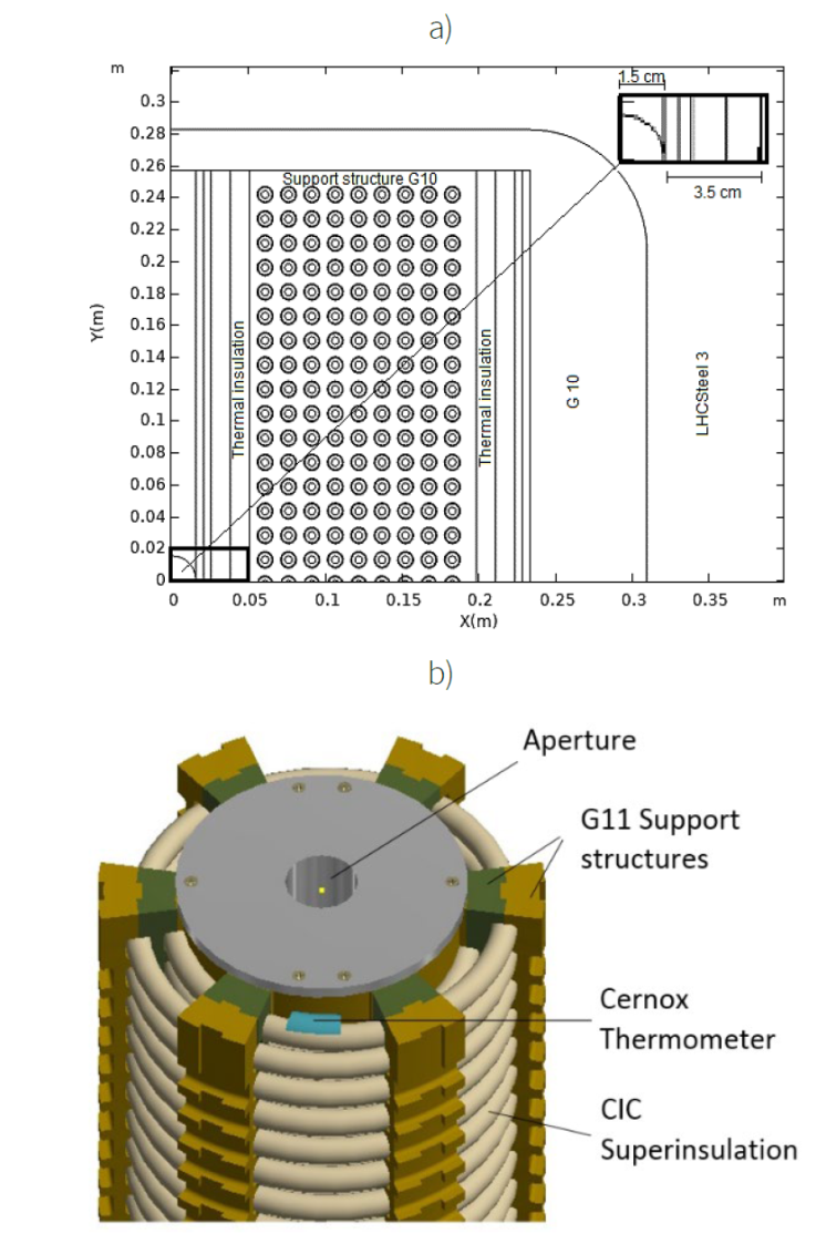
Figure 4 a) Cross-section of a guarter cut for the superconducting solenoid. b) Solenoid structure with G-11 supports, superinsulation around the CIC conductors, and thermometers along the winding to monitor CIC temperature during operation.
A package of CIC conductors is placed on 6-G11 support structures that guide the winding layer by layer after the insulation system. G11 and G10, are fiberglass epoxy compounds, with high strength mechanical properties (Tensile strength 872 MPa and Young’s modulus 32 GPa, in the crosswise direction (Goodzeit, 2001)) at cryogenic temperatures (4K) and low thermal conductivity (0.25 W/m K) (Kasen et al., 1980).
Specially designed transition G-11 blocks are used for the transition layer. An azimuthal spacing in between G-11 structures is intentionally left for two reasons: it allows us to determine the winding position and its relationship with the field distribution; and will enable us to install cryogenic resistant Cernox thermometers (Brandt et al., 1999) to monitor the temperature every 30 meters, see Figure 4b.The thermometers constitute a secondary quench detection system, while the use pickup coil has proven to be an efficient method for quench detection (Jongeleen et al., 1997). An Hp-Vee (Beethe & Hunt , 1992) computer program was built to collect the data from the high- precision multimeters connected to the pick-up coil. The software detects any voltage increment associated with a quench event. When the pick-up coils see the signal, the current dump resistor; simultaneously, the quench protection system will send a 5 A current pulse to the 25
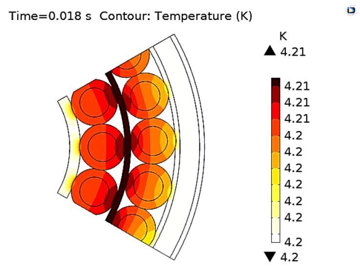
Figure 5 The fifth section of a 2-layer CIC conductor. The figure shows the heat distribution induce by a 5 A current passing through the 25
A 2d finite element analysis (FEA) simulation was carried to model the transversal heat dissipation considering forced flow cooling (Wilson, 1983) at the center of the CIC conductor. We have explored different designs to produce a 10 T solenoid; nevertheless, we could only achieve this by using wind-and-react superconductors such Nb3Sn, MgB2, or Bi2212. Unfortunately, we do not count on the equipment necessary to carry out a high precision heat treatment; furthermore, to use wind-and-react superconductors, we must change the materials in the CIC, like the high-strength CuNi outer tube, for a thermally resistant material in the range of 680 C (for Nb3Sn), like Model 400.
We designed a superconducting solenoid with an operational field ranging from 6T -7T using NbTi double-layer CIC conductors, with a homogenous region 3x of commercially available superconducting solenoids (whose homogenous region range from 2.5 cm to 3 cm in height (Cryogenic, 2021)). The implementation of CIC superconducting technology provides two advantages over conventional superconducting Rutherford cables; From the manufacturing point of view, CIC technology does not require epoxy impregnation of superconductors; making easier the manufacturing process. The epoxy impregnation reduces thermal stability avoiding direct contact between superconductors and coolant. In CIC, the superconductors are in direct contact with the coolant. From the operational perspective, the CIC acts as its own cryogenic vessel, requiring an estimated helium flow rate of 2 g/s (Ghoshal et al., 2019) to control temperature rise within 1 K (based on helium-4 mass density, a cross- section of the CIC central channel, and fluid velocity), contrary to conventional conducting solenoids (Becchetti et al., 1993; Endig & Lange, 1968) where large cryostats are required, and consume a large amount of liquid helium during the cooling and operation at normal phase current leads at 1kA typically require 1.69 1/hr (Kittel, 1996) , consumption of 0.7 1/hr during operation without current leads (Sohn et al., 2002), and a flow rate of 5 g/s (Pamidi et al., 2012). These advantages suggest that our proposed design could reduce operational costs. A detailed cost analysis is required. Nevertheless, it runs out of the scope of the present work and it merits a separate publication.
Upon completion of the winding process, a stainless-steel coffin will pressure load the superconducting winding; a 7 cm G-11 spacer will be put around the coffin for magnetic modeling purposes, see Figure 5.
To further reduce the production cost, we have conducted an optimization study to determine the best confirmation that allows us to generate a magnetic field of 7T at the aperture, with a minimum length of CIC conductor.
In the optimization procedure, we studied different CIC configurations, varying the number of CIC per layer, and recording the height of the uniform region at the aperture, where the field is constant in determine the size and positioning of the borosilicate test tube, and if it’s large enough, it will allow us to place two samples vertically, one on top the other.
Figure 6 shows the magnetic field distribution at the center of the aperture produced by different scenarios varying number layer and rows. Using only five rows is practically impossible to achieve 7T at the center of the aperture, even if the number of columns increases to an unrealistic number of 60. Even for this configuration, the operational current density limits the field to a maximum of 6.4 T, increasing unnecessarily the length of the required CIC conductor to 261 m (Figure 7.). On the other hand, using 30 or 35 rows allows us to achieve 7 T, with 11 or 10 layers, respectively, reducing the total CIC length. To deeply explore this range, we performed individual simulations varying the number of rows in the range from 30 to 35 rows and combination produces a 7 Tesla magnetic field with a minimum length of CIC. Simulation results suggest that using 33 rows and nine layers, we can achieve a uniform magnetic field of 7 T in a region 3Cm wide x 10 cm height, with a field homogeneity of 2.2 %. The homogeneous region lies at the center of the solenoid length. This configuration requires 132 m of double-layer CIC, which lies within the manufacturing capabilities (Breitschopf et al., 2017). Table 2 summarizes the coil distribution study, showing the expected magnetic field, its homogeneity, and the length of the homogeneous region within the solenoid aperture length of CIC, and yet is uncapable of achieving the 7 T target field.
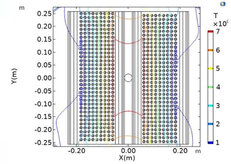
Figure 6 Magnetic field contour across the solenoid. Isolines confine the regions with a constant magnetic field magnitude. The height of these regions will determine the position and number of samples placed in a single experiment.
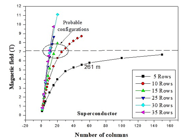
Figure 7 The magnetic field at the center of the aperture is a function of the number of rows and layers. Notice that for the 5-row case, the maximum magnetic field inside the chamber does not reach the 7 Tesla target field, requiring an unrealistic number of columns, and increasing the length of required superconducting CIC to 261 m, exceeding the production capabilities.
Table 2 Magnetic field distribution.
| R | Magnetic field (T) | Field Homogeneity* (%) | R*L | Height at 7T (cm) | CIC Length (m) |
|---|---|---|---|---|---|
| 5 | 6.4 | 9.3 | 5*60 | - | 216 |
| 10 | 7.3 | 6.3 | 10*30 | 3 | 233 |
| 15 | 7.0 | 5.8 | 15*18 | 5 | 159 |
| 25 | 7.0 | 2.8 | 25*11 | 6 | 131 |
| 30 | 7.4 | 1.7 | 30*11 | 8 | 157 |
| 35 | 7.15 | 1.3 | 35*10 | 10 | 161 |
R*L: Rows*Layers
*Field homogeneity is measured as the radio: (Bmax-Bmin)/Bmax measured in a region 3 cm wide x H cm height where “H” is the height for each configuration, with values shown in column five.
With the magnetic field distribution across the superconducting solenoid, we could study the magnetic force’ vector behavior to determine the effect on the G11 support structures. As mention earlier, both the G10 and G11 are epoxy fiberglass compounds with high mechanical strength at cryogenic temperatures (Funke & Haberstroh, 2012). The 3D magnetic field distribution will act on each CIC, exerting a radially outward magnetic force on each of the six avoided by machining the parts in the through-plane direction, so the CIC lies perpendicular to the XY plane.
A Von mises stress simulation measures the expected net displacement of each support structure’s X, Y, and Z direction, due to the radially outward force, Figure 8. The structures simulation used mechanical properties of the G11 compound at cryogenic temperatures (4K). A safety factor of 15 shows not enough elastic energy of distortion to damage the G11 pieces’ structural integrity permanently.
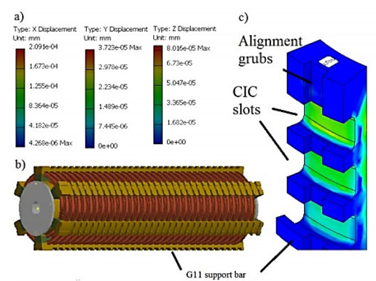
Figure 8 Von mises stress analysis on the G11 Support structures due to the magnetic force of CIC conductors. Figure a) shows the net displacement on the X, Y, and Z direction for the first layer of G11 support structures due to the magnetic force for the first layer of 33 CIC. Figure b) shows a side view of the 7 Tesla superconducting solenoid, showing the support structures for the first two layers (of a total of 9). Figure c) shows a zoomed view of the inner support structure. The CIC slots offered in the picture position the CIC in place. A set of alignment grubs on each G11 support structure ensure the correct positioning and alignment of the supports during the winding procedure.
4. Conclusions
The applied superconducting lab at Universidad de Guanajuato has envisioned developing a non-conventional superconducting solenoid using cable-in-conduit technology. Superconducting solenoid is designed to tackle material science fundamental research. High magnetic fields are required to induce a forced orientation on crystal substrates during the sublimation phase, which is meant to increase the electrical conductivity on crystal structures. The present design provides two technological improvements over conventional superconducting solenoids: It incorporates a thermally isolated chamber, kept at room temperature, where test tubes containing substrates are placed. The device allows the user to control the temperature of the sample within a range from 20°C to 200 °C. The other improvement is that it provides an operational magnetic field of 7 T, homogenous at a region 3 cm wide and 10 cm height, 3x of what commercial technology offers. The work also presents a preliminary magnetic study that suggests an optimum configuration for producing 7 Tesla by using 33 rows and nine layers; this arrangement reduced the required length of the CIC conductor, from 261 m to 132 m, as compared with other rows/layers configurations. A magnetic force study and a von mises stress simulation show that the support structures for holding in place the CIC superconductors.
Further studies are required to determine the optimum configuration for the cryogenic stability of the superconductors, the design of low resistance splice-joint for powering the CIC conductors, and a cost optimization procedure.

