This paper is in honor of Dr. Omar Solorza-Feria as an electrochemical member of emeritus researcher of the Mexican National System of Researchers, SNI.
Introduction
Recent studies reflected the growing consensus that it will be inevitable to initiate and accelerate the energy transition from traditional energy systems to innovative and sustainable alternatives. The integration of energy systems with the coupling of clean sources to produce electricity represents a solution to problems related to environmental pollution, climate change, damage to health and energy supply. In recent decades, the direct conversion of chemical energy to electrical energy via fuel cells has been the focus of electrochemical research and technological developments. The interest in studying fuel cells rests fundamentally on two factors: the high efficiencies in energy conversion, and the noticeable decrease in pollutants emitted into the atmosphere. Fuel cell technology requires an interdisciplinary involvement, which ranges from the use of different fuels, mainly hydrogen, and it´s processing, through knowledge of basic concepts in electrochemistry, chemical and mechanical engineering, and automatic control systems [1]. Hydrogen, a clean energy source with the highest specific energy density, represents the best alternative to batteries and fossil fuels used in conventional energy production [2-4]. Efforts are still being made to improve the performance of Fuel cell hybrid electric vehicle (FCHEV) prototypes as powertrain layout, PEMFC system integration, and energy management strategy solutions among others as the developments reported in [5-8]. In [5] a 10 kW PEMFC system was developed and tested for a five-seater small car using a hydrogen tank type III. In this communication we present the design, manufacture, and performance results of a fuel cell hybrid electric vehicle prototype (FCHEV), H2/O2 PEMFC along with Li-ion batteries, considering reliability and sizing space and taking into consideration that the use of this technology reduces to zero the pollutants into the environment. The work is organized as follows: Section II describes the design methodology for the chassis, powertrain, PEMFC stack, and battery module. Section III presents the development of the prototype, and the experimental behavior of the powertrain at a suitable speed cycle for small vehicles. Finally, conclusions are given in section IV.
Development of the FCHEV prototype
Chassis building
The chassis design, proposed using computer aid design (CAD) methods, was conceived for three passengers, the front driver, and passengers, as well as for a person in a wheelchair and a rear passenger in back. Fig. 1(a) -1(d) shows several computer design sights produced in Solid-works software [9-10] and Fig. 1(e) shows a structural deformation simulation carried out by ANSYS Workbench platform with finite element analysis (FEA) against a frontal collision at a velocity of 50 km/h as reported in [11-13]. The body of the prototype was projected to be made of round tube aluminum alloy type 6063-T6 with 33.4 mm external diameter and 26.64 mm internal diameter.
PEMFC design
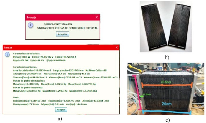
The design of PEMFC stack is based on a numerical modelling developed by our research group, [14]. An algorithm developed in Java combines stoichiometric calculations for the reaction 2H2 + O2 → 2H2O [15-16] and the Ohm’s law for the electric circuit calculations. Required input parameters include power, current collector plate, and output voltage among others. The output results are the number of current collector plates, effective area of plates, maximum and optimized values of power, voltage, and current, the expected volume and weight of PEMFC stack, and the expected consumption of H2 and air, see Fig. 2(a). The bipolar plates are made of good conductor high resistivity graphite, with a channel pattern that facilitates the gas flow on each face of the electrodes. At the same time, they make electrical contact with the surface of each alternate electrode. A computer numerical control (CNC) milling machine with an optimized channel pattern program was employed to fabricate polar, bipolar, and final plates, see Fig. 2(b). The PEMFC stack was fixed with forty-eight membrane-electrodes, MEAs, in a single cell with an electrode surface geometric area of 123 cm2 for anode and cathode sides. This configuration creates a stack that feeds serpentine channels to feed humidified air-dry hydrogen and horizontal channels to feed air above the cathode. Fig. 2(c) shows a compact PEMFC stack arrangement which benefits the electric current flow. The edges of the electrodes are sealed with silicone gaskets, also around each MEA to avoid short-circuit in between them. The PEMFC stack dimensions are 26 cm large, 8 cm wide, and 20 cm high.

Fig. 2 PEMFC development. (a) PEMFC numerical modeling [10]; (b) Bipolar plates with serpentine; (c) PEMF stack assembly.
Li-Ion battery sizing
Li-ion cells are the most widespread technology in EV’s because of their small size, high current density, and availability [17-18]. Containing a grid of Ns serial connected and Np parallel connected cells, battery module increases the charge storage capacity, the discharging current, and the open-circuit voltage of a single small Li-Ion cell. The battery module should be sized for the expected vehicle cruiser velocity as the installed electric motor power size for the specific drive-cycle. As mentioned in [19] an early estimation of the required electric power for an HEV is approximated by the equation (1):
where V is the velocity, M is the mass, fr is the friction coefficient, ρ a is the humidity factor, A f is the drag coefficient, η t is the transmission ratio (wheel radius to motor-shaft ratio), and η m is the efficiency of the motor. Once the module power requirement is estimated, module voltage v b should correspond to the nominal supply voltage vs of the motor-drives and the module discharge-current i b might increase as the expected autonomy in hours. As described in [17], module voltage and discharge-current determine the series cell number Ns per string and the parallel string number Np respectively of the projected Li-Ion battery module by:
where v c and i c are the nominal voltage and current of a single Li-Ion cell.
FCHEV Powertrain
Fig. 3 shows the simplified diagram of a series powertrain for FCHEV [20]. The structure includes a PEMFC stack and a switch-mode DC-DC converter as power conditioning unit (PCU), Li-Ion battery module, motor-drive, brushless direct-current (BLDC) motor, transmission ratio, and vehicle body dynamics. An energy management strategy (EMS) schedules the PEMFC energy source and Li-ion battery module to alternatively deliver the supply voltage vs for motor-drives, see [21-22]. The motor-drive internal speed control loop modifies the motor voltage vt and takes the angular speed ω close to a velocity command ω m *. Comprising speed values versus time, the velocity reference is a drive-cycle or the vehicle driving pattern. It involves well-known periods such as: constant acceleration, constant velocity, brake, and zero speed or a no-movement period. The vehicle body involves mechanical parameters such as weight, speed ratio, rolling force, etc. The instantaneous rolling resistance on wheels acts as load torque τL for the BLDC motors.
Results and discussion
Fig. 4 shows the Cinvestav FCHEV prototype named Sicarú, made of an aluminum tubular structure taking into consideration frontal impact studies of the entire vehicle body, at a speed of 50 km/h, and it would be absorbed by the impact attenuators as it is shown in Fig. 1(e). The structure measures 270 cm length, 140 cm width, 170 cm height and weighs 280 kg. The external cover of the prototype was made of fiberglass. Table 1 shows other specific body parameters of the developed FCHEV.
Table 1 Specifications of FCHEV.
| Cd | fr | Af (m2) | Mass (kg) | Rd (m) | Battery (kW) | PEMFC (W) | BLDC Motor |
| 0.3 | 0.01 | 1.5 | 280 | 0.27 | 3.7 | 520 | 800W,36V |
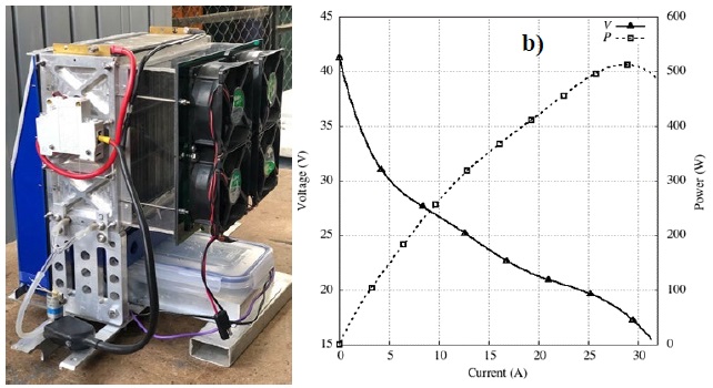
Fig. 5(a) shows the PEMFC stack assembly with auxiliar subsystems, such as cell humidification, air fans for oxygen supply, hydrogen connections, solenoid valve for hydrogen purge, and the electrical main switch. Fig. 5b shows the PEMFC stack voltage against current curve under controlled test conditions with a maximum power point of 520W at 18V, 29A. Table 2 shows the main specifications for the developed PEMFC stack. A 1,400-liter hydrogen tank is installed behind the driver of the prototype vehicle, and the PEMFC stack consumes 520 liter per hour of pure hydrogen per hour.

Fig. 5 PEMFC source for HEV. (a) Front view of PEMFC source; (b) Performance under controlled test conditions.
Table 2 Parameters of developed PEMFC source.
| Type | Ns | A (cm2) | J (mA/cm2) | Power (W) | Material | Reactants | Reactant Pressure (atm) |
| PEM | 48 | 123 | 235 | 520 | Pt, 20% | H2, air | 0.2 |
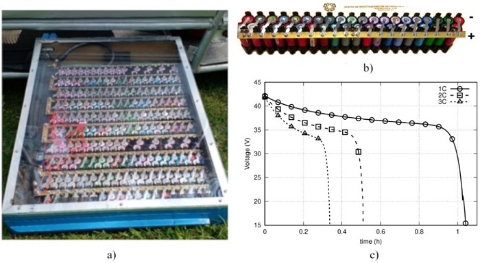
Because Li-Ion cells have high energy density and high availability [18], several 400 cells of the type ICR18650 [23] shape the entire battery module. A 3.7kWh battery module was obtained by means of a configuration of 10 series connected cells and 40 parallel connected cells also known as a 10S40P configuration. Fig. 6(a) shows the in-situ Li-Ion module, Fig. 6(b) shows one building block Li-Ion cell formed by 1S40P configuration. Fig. 6(c) shows the theoretical performance carried out by the methodology given in [24]. Table 3 shows the specifications of the battery module.

Fig. 6 Li-Ion Battery module. (a) In-situ battery module with a 10S40P configuration; (b) Building block Li-Ion cell with a 1S40P configuration; (c) Expected perfomance of the Li-Ion battery module.
Table 3 Specifications of the Li-Ion battery module.
| Li-Ion Cell | Li-Ion Module | |||||
| Type | Nominal Voltage (V) | Nominal Capacity (Ah) | Ns | Np | Voltage (V) | Energy (kWh) |
| ICR18650 | 3.6 | 2.6 | 0 | 0 | 36 | 3.7 |
A four-wheel drive (4wd) powertrain configuration is achieved through a single 800W per wheel BLDC motor. Fig. 7 shows the behavior of the powertrain under a 40 second single drive-cycle. This behavior is described by developing an oscilloscope measurement of the motor-drive current. According to the EMS schedule, the Li-ion battery module must provide the required motor-drive current during the acceleration phase, while the PEMC stack should provide the required current during the cruiser speed phase. The acceleration period lasts ten seconds and its maximum motor-drive current was around 75 A. By the constant velocity lapse, a speed of 25 km/h is reached, and the developed motor-drive current was only 40A. The negative motor-drive current corresponds to the regenerative brake period that returns a small fraction of energy to the supply source. Finally, powertrain holds a zero speed, and no motor-drive current is developed.
Conclusions
A hybrid vehicular transport prototype with H2/air PEMFC and Li-Ion batteries was designed, manufactured, and electrochemically characterized. The PEMFC stack global parameters was estimated by a simple numerical algorithm. CAD tools are used to design and to construct the unipolar and bipolar plates of the PEMFC stack. The parameters of FCHEV were determined for real-time testing of the PEMFC system, battery module, BLDC-motors, vehicle body dynamics, and control algorithms. A Li-Ion battery module was developed, assembled, and tested in our laboratory for a constant current discharge. The performance of the powertrain is characterized under a complete drive-cycle for motor-drive currents. The battery module capacity met the power requirement for FCHEV for maximum velocity of 32 km/h. Battery module and PEMFC stack is an exceptional solution to improve the performance of the FCHEV by enlarging the autonomy of batteries, and by applying a renewable energy source in electric transport. It is expected that in the following years the hybrid electric vehicle prototype grows in Mexico as the beginning of a substantial production of them to reduce the breach with classic gasoline vehicles.


 nueva página del texto (beta)


