1. INTRODUCTION
Corrosion damage of reinforced concrete structures, particularly in marine environments, is a serious problem worldwide. It incurs costly repairs and can threaten user safety in severe cases. This problem is particularly acute in reinforced concrete beams, because they experience tensile forces from flexure loading, making it almost impossible for them not to develop micro cracks. These constitute an entrance path for corrosive substances to arrive at the carbon-steel reinforcement bar and activate it. In well-designed beams, thin transverse cracking due to flexure loading is always present. These are normally invisible to the naked eye, and do not affect durability in most cases. As mechanical loads (applied directly to beams) increase, both crack number and width increase, commonly reaching widths of approximately 0.25 mm. If loads continue to increase, crack width will increase, although crack number changes little (ACI 224, 1992).
In the steel reinforcement model proposed by Tuutti (Tuutti, 1992), T1 (initial corrosion) is defined as the period between structure fabrication and the start of corrosion, and T2 (propagation) as the time between the start of corrosion and manifestation of external damage, when a structure attains an unacceptable level of deterioration in terms of safety, functionality and/or aesthetics. In addition to
Tuutti’s two stages (T1 and T2), a third stage (defined here as residual life), has been described that begins from degradation symptom appearance (e.g. cracks > 0.1 mm in width; concrete spalling; visible loss of steel section, etc.) and ends with structural collapse. During this final stage, load capacity progressively degrades in the corroding structure (Troconis de Rincón y col., 1997). In other words, the residual life can be considered as the time during which a structure must be repaired before collapsing.
The easiest stage to detect during visual inspection of a concrete structure is the residual life stage since wide cracks, surface rust stains, and concrete spalling are clearly visible to the eye. However, to evaluate if a structure is in stage T1 or T2 (service life) requires more complex, costly diagnoses. In addition to visual inspection, electrochemical monitoring must be performed to determine steel activation, corrosion rate estimation to indirectly document steel mass loss due to corrosion, extract test cylinders from the concrete element to measure chloride concentration at reinforcement depth, etc. Once corrosion rate and steel cross section loss are quantified, a prediction of structural damage can be generated.
Corrosion rate measurements indicate the amount of metal that has been transformed to oxide per reinforcement surface area and time. The amount of oxides generated is directly related to concrete cover cracking and adherence loss. Reduction in steel transverse cross section affects structure load capacity, and corrosion rate is therefore an indicator of decline in structure load capacity. Load capacity reductions in reinforced concrete elements affected by reinforcement corrosion are fundamentally due to four effects: 1) rebar cross section reduction; 2) rebar ductility reduction; 3) rebar/concrete adherence reduction; and 4) loss of effective concrete section due to concrete cracking. (Torres y Martínez, 2001)
Previous studies (Andrade y col., 1993; Cabrera, 1996; Rodríguez y col., 1996; Rodríguez y col., 1997; Tachibana y col., 1990; Torres y Sagües, 2000; Torres, 1999; Torres, Castro, Sagües, 1999; Torres et al, 2007) have evaluated corroded beams using accelerated corrosion tests and crack mapping survey to calculate the remaining load capacity (RLC) value for structural elements with generalized corrosion, based on easily measured damage such as corrosion-induced average surface crack width. The data in these studies (Torres y Martínez, 2003; Torres et al, 2007) indicate that during the residual life stage is when a structure’s RLC begins to decline rapidly: corrosion radius loss is directly proportional to the crack width in the concrete surface. Therefore, this investigation will determine empiric correlations, which may allow the evaluation of how reinforcement corrosion may affect concrete surface crack initiation and propagation, in length as well as in width, to predict the structure’s durability, and prevent higher deterioration impact that may increase repair costs and eventually its failure, for the particular case of loaded beams.
2. EXPERIMENTAL PROCEDURE
Twenty-four beams (1200 x 100 x 150 mm) were made with a 9.5 mm diameter steel bar with a 25 mm concrete cover. Concrete’s capillary sorption was determined using the Sweden Standard also known as Fagerlund Method (Fagerlund, 1986). The procedure include the fabrication of cylindrical specimens (10x20 cm), which after a curing period of 30 days, they were dryed at 50oC up to constant weight; afterwards they were placed in wet sponges in a wáter container and weighed for several days until reaching constant weight.
The middle section (250 mm long) of all twenty-four beams (Cl- contaminated and non Cl- contaminated), was sprayed with a 3.5% w/w NaCl solution twice weekly (on the face closest to the steel rebar) to further accelerate the steel rebar activation process via Cl- ion diffusion from the exterior.
Half of each set of concrete beams (Cl- contaminated and non Cl- contaminated) was placed under constant flexure load for one year. This simulation of normal loads in real beams was done to evaluate the effect of flexure on corrosion rate and overall beam durability. Beams with this applied load are defined in this investigation as preloaded beams.
2.1 Concrete beams evaluation
Rebar half-cell corrosion potentials were measured twice weekly using a saturated Cu/CuSO4 electrode at three points along the steel rebar, similar to a potential mapping procedure (ASTM C876, 2009). Corrosion rates were measured at three points along the steel rebar using the linear polarization method and a GECORR-6 field test device (rebar central zone and end zones).
To simulate the influence of flexure loading on corrosion of steel rebar in concrete structures, a constant center flexure load of 500 kg was applied to twelve of the beams in six preload systems, containing two beams each. Load was applied at three points (center and each end), as observed in Figure 1, making six preload systems with two beams each. Once every month, visual inspection was performed to the twenty-four beams (with or without flexure preload), to determine the appearance of surface cracks after. If surface cracks appeared at the beam’s surface, a detailed crack survey was performed, including its location, length and width.
2.2. Results Analysis for correlation determination
The corrosion rate data were used to calculate rebar section loss with the Faraday Law conversion:
Where:
∆W F = mass loss (g)
n = iron valence (Fe+2)
F = Faraday constant= 96,500 coul/mol
Fe Atomic weight = 55.85 g/mol
∫ I.dt = ∫icorr (A)dt = Area below the icorr vs. time curve
This mass loss value was then used to estimate average radius loss from corrosion (xAVERAGE) (Geocisa, 2000). These xAVERAGE values were correlated to concrete crack width over time.
Where:
3. RESULTS
The mixture design was defined using ACI 211.1 method (ACI 211.1, 1993), using a 0.60 water to cement (w/c) ratio concrete. The beams were made with a concrete rated as moderate performance in marine environments: capillary sorption = 1.50x10⁻⁴ m/s0.5; effective porosity = 8.3-8.8%; average 28day compressive strength = 330 kg/cm2.
3.1. Electrochemical evaluation
Electrochemical measurements were taken during a three-year period (approx. 1,100 days), long enough to allow the steel rebar to activate (< -200 mV vs. Cu/CuSO4), as observed in Figure 2. Preloading had no significant effect on half-cell potential values in the experimental period because the rebar was already active when the flexure load was applied.
Spraying with NaCl solution, rather than the preloading, caused the half-cell potentials in the beams’ central portion to be more negative than the ends. Rainfall also affected steel rebar activity, which is to be expected since it lowers concrete resistivity. As occurred in the Cl--contaminated beams, the non Cl-contaminated beams had half-cell potentials vs. Cu/CuSO4 electrode values indicating no significant effect from the applied preload (Figura 3).
Figure 4 shows that rebar corrosion rate was not significantly affected by preloading, confirming halfcell potentials measurements (Figure 2). It was higher in the central portion of the bars’ due to spraying with NaCl before and after preloading. The variation observed in corrosion rate was due to the effect of rainfall, which diminishes concrete resistivity.
The preloaded, non Cl--contaminated beams that had been sprayed with NaCl in their central portion (Figure 5), initially exhibited some activity at all tested points. They then attained passivity and apparently remained so until the load was applied, when the half-cell potentials measurements indicated activity in the steel rebar, corroborating half-cell potential results obtained.
However, the same effect was observed in the non-preloaded beams. This suggests that preloading was not the cause of the increased corrosion activity, but rather the combined effect of the Cl- ions and high rainfall during the experimental period. This is clearly visible during dry seasons, when corrosion rates decreased but values still indicated activity in the reinforcement (0.1 µA/cm2), especially in the central zone.
3.2 Visual inspection and crack survey
When corrosion cracks appeared in the beams, monthly visual inspections and crack surveys were begun. Once the experimental period had ended, the beams were mechanically tested, until rupture.
3.2.1. Non Cl - contaminated beam systems
Neither parallel no perpendicular cracking were apparent in the non-preloaded beams (Figure 6a), even with spraying of NaCl in the central 250 mm section. Corrosion rate values indicated activity (> 0.1 µA/cm2), but it was insufficient to generate crack appearance on the concrete cover surface. As shown in the electrochemical parameter values, the preloaded beams (Figure 6b) exhibited only perpendicular cracks (< 0.15 mm) due to preloading. These did not enhance reinforcement corrosion during the experimental period.
3.2.2. Cl - Contaminated beam systems
In non-preloaded beams (Figure 7a), it was observed in the central zone, where chloride rainsed was performed, cracks parallel to the rebar appeared, having 0.40 mm maximum width. In preloaded beams (Figure 7b), corrosión cracks reached 0.8 mm widths. This indicate that the initial chloride contamination helped corrosión crack initiation.
3.3. Crack opening rate vs. i CORR correlation
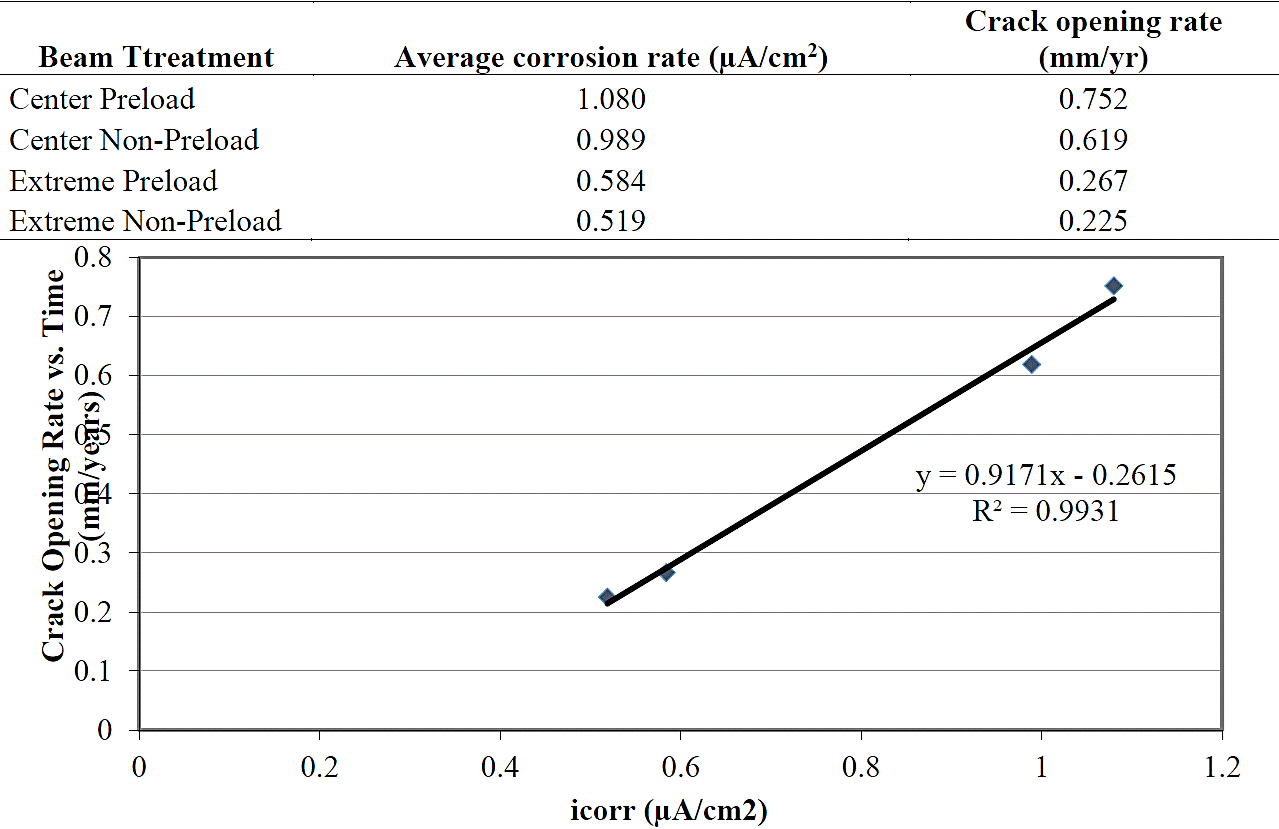
Figure 8 shows average conditions of the evaluation performed. As observed in this figure, in central zone, average corrosion rate are similar for preloaded as well as non-preloaded beams (1.080 - 0.989 μA/cm2, respectively). Same corrosión rate behavior was observed at the end zones of same beams (0.584 - 0.519 μA/cm2, respectively) (Figures 4 and 5). Differences were present, however, between the central portion and ends of each beam treatment, due to spraying with NaCl solution in the former.

Figure 8 Average slope for crack width opening rate and reinforcement corrosión rate (Hernández, 2009)
A good correlation was observed between crack propagation rate and steel rebar corrosion rate (Figure 8). This phenomenon has been reported previously [Alonso y col., 1998] in a study using an accelerated corrosion method involving an anodic current applied to the rebar inside chloride contaminated concrete (10 and 100 μA/cm2), and crack propagation rate was higher at the lower current intensity (low corrosion rate). In contrast to this previous study [Alonso y col., 1998], the present results indicate that with natural corrosion at low icorr values (< 1.2 μA/cm2) crack width propagation was directly proportional to the rebar apparent corrosion rate.
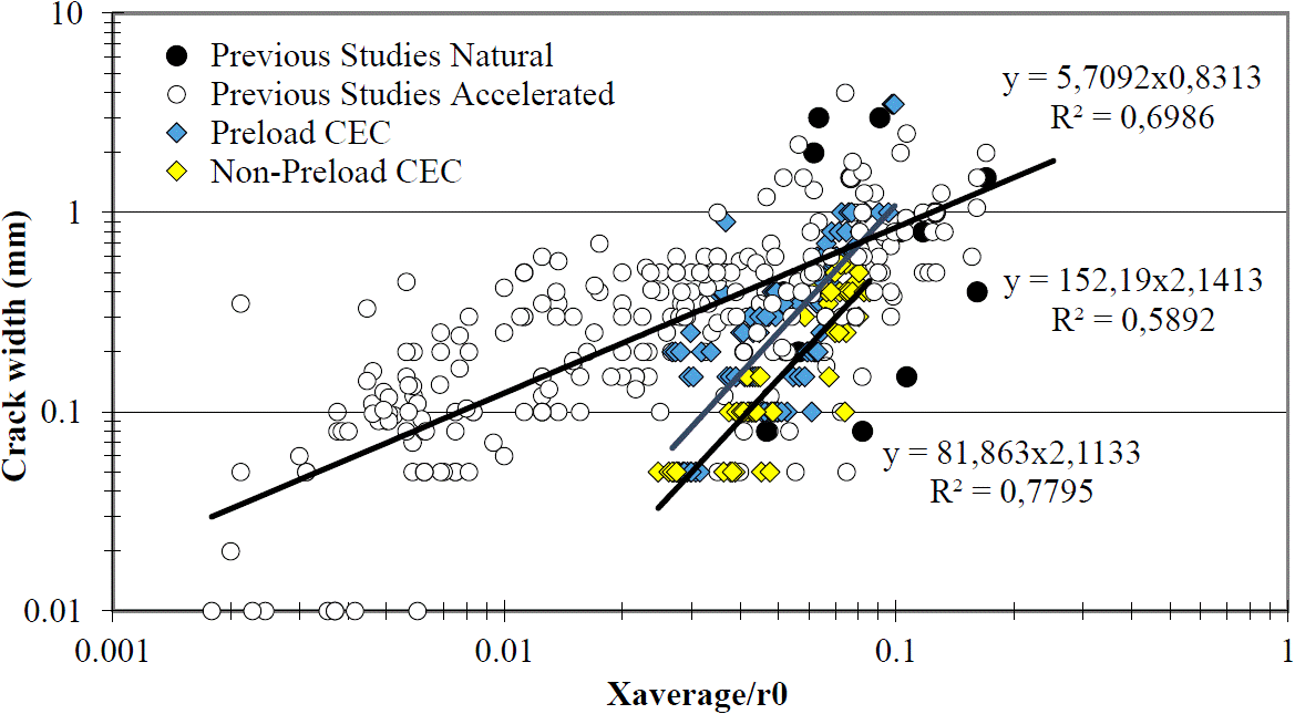
Figure 9 shows the correlation between máximum crack width and average rebar corrosión penetration of all tested beams, preloaded and non-preloaded, (natural corrosión, performed at CEC, Corrosion Studies Center, Venezuela), together with accelerated corrosion data for comparison purposes (Andrade y col., 1993; Cabrera, 1996; Rodríguez y col., 1996; Rodríguez y col., 1997; Tachibana y col., 1990; Torres y Sagües, 2000; Torres, 1999; Torres, Castro, Sagües, 1999; Torres et al, 2007). CEC data, preloaded and non-preloaded, shows for a determined crack width, less corrosión is needed when beams are preloaded as if the beam in non-preloaded (preloaded beams data trendline is shifted to the left of the non-preloaded beams data trendline). Results demonstrate the existence of a direct relationship between crack width and rebar corrosión rate, and observing wider crack son the preloaded beams. Figure 9 shows an interesting tendency where natural corrosion data presented a smaller slope in its tendency lines than the natural corrosión tendency line slope.

Figure 9 Maximum crack width vs. cross section loss (Xaverage/r0) data from the CEC and previous studies
Under accelerated corrosion, cracks were produced with less steel loss, apparently because corrosion products rapidly accumulated near the reinforcement, generating high tensile stresses that caused cracking. Additionally, the anodic current may also have generated acidity at the steel/concrete interface, undoubtedly lowering adherence between the two materials (steel and concrete) and facilitating crack generation. In contrast, under the natural conditions studied here, corrosion was considerably slower, allowing corrosion products to migrate and thus requiring the accumulation of more products before cracking began.
This may indicate that accelerated corrosion to simulate degradation in real structures therefore does not always produce results comparable to those of natural corrosion.
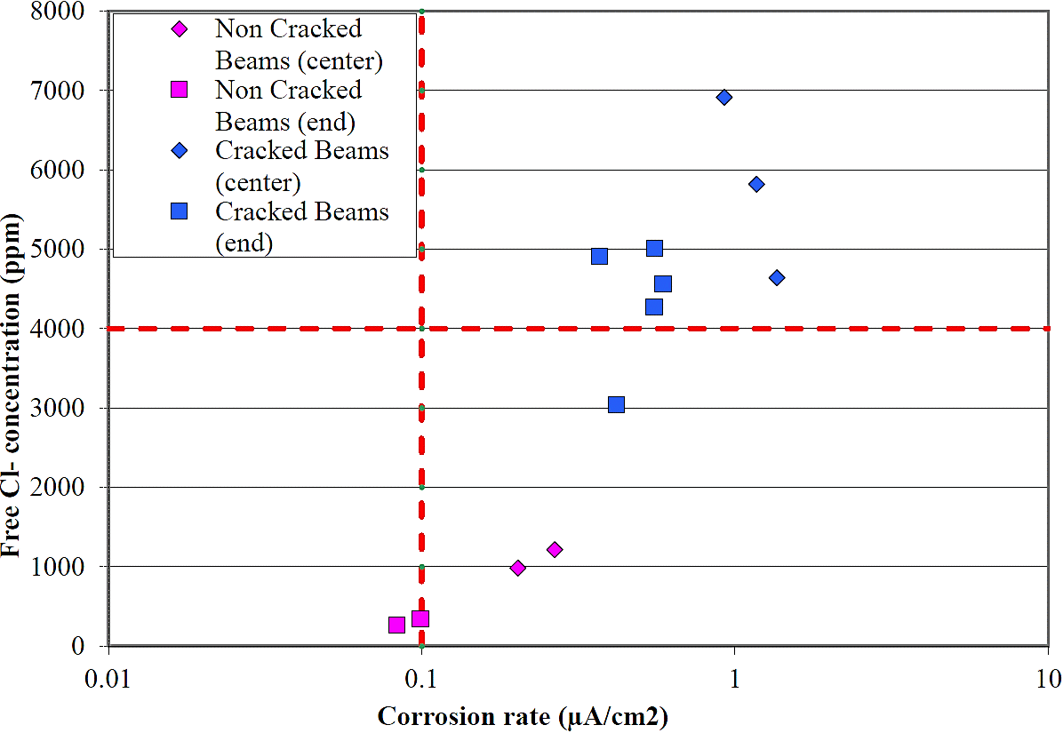
Analysis of chloride ion concentration at the reinforcement bar (Figure 10), showed that cracked beams had higher chlorides concentrations near the rebar, because the cracks allowed the NaCl solution, sprayed on the beams, to more easily penetrate the concrete and reach the rebar, increasing the concentrations up to higher values than the chloride threshold limit (4,000 ppm Cl-), with respect to the non cracked beams.

Figure 10 Chloride ion concentration at the rebar depth vs. corrosión rate, cracked and non cracked beams (Hernández, 2009)
This corroborates the results of a study evaluating concrete test cylinders from structurally cracked bridges in which chlorides were found to have penetrated the concrete more easily in cracked zones than in those without cracks (Sagües y col., 2001). The results indicate that free chlorides content was higher and corrosion rate greater in the center of the beams, corroborating how the preload increased chloride penetration (due to higher crack propagation rate) and the corrosión rate increased base don this increase of free chloride concentration.
4. CONCLUSIONS
Electrochemical analyses showed that crack widths < 0.15 mm do not enhance reinforcement corrosion during the evaluated time period.
Preloading accelerates the reinforcement corrosion process by allowing greater entry of aggressive compounds.
Accelerated corrosion of an element causes crack appearance with less steel loss. Natural corrosion, in contrast, requires more corrosion product accumulation before cracking begins.
A direct relationship exists between crack width and corrosion-induced rebar cross section diameter loss, with wider cracks in flexure loaded beams.
In a natural corrosión process, to obtain a similar crack with value than in an accelerated corrosión process, less corrosión cross section loss in needed when specimens are nonpreloaded. There is also an increase in corrosion crack propagation when natural corrosion beams are prelodad than when are non-preloaded.


 texto en


