1. Introduction
The gas turbine implementation has increased because it is one of the most trustworthy technology to convert flowing energy to efficient and useful work, also with regulated contaminants emissions and moreover for its flexible operation to use gas and/or liquid fuels 1-5. Then, due to the worldwide natural gas availability and the global infrastructure for its distribution, the most viable technology to satisfy the energetic pick demand of the emergent economies like Mexico, could be the gas turbine 6-7.
The gas turbine behavior is described by means of the thermodynamic Brayton cycle which starts by the continuous confinement of a certain amount of atmospheric air. This air is compressed by a set of blades accommodated at the stator and rotor into the compressor stage. Then this air is mixed with the injected fuel and this mixture is burned into the combustion chamber; here is where the power is added and extracted from the fuel. Therefore this power concentrated gets away by its expansion through the turbine blades and consequently by moving the engine rotor 8-10.
The flow behavior through the gas turbine strongly defines this device performance; so that, it is important do not only estimate or measure punctually the flow magnitude into the different engine stages, it is needed to know the dynamic flow distribution profile also 11-12.
1.1. Current technologies for the flow analysis in gas turbines
To analyze the concerned flow distribution profile in the gas turbines, the state of the art mainly reports the implementation of four techniques: Computed Flow Dynamics (CFD), Velocimetry and Image Processing, Doppler Effect and the escalation from punctual measurements sampling.
Because of its accuracy, the CFD is the most used technique to analyze the aerodynamic profile of the compressor and turbine blades; but because of its complexity and the large amount of interactions needed for its solution, its experimental implementation online is not an option 13-14.
There is a high relationship between both techniques CFD and Velocimetry (complemented with image processing); because them both have been used to validate mutually their results for the flow distribution profile analysis in aerodynamic experiments. But again, both implementations in situ with gas turbine engines are almost impossible because of the facilities and infrastructure needed 14-15.
Several experimental set ups based on the Doppler effect have been implemented to analyze the air flow behavior in the compression and expansion stages from different engines topologies; but the implementation of these techniques in gas turbines is limited, because the Doppler effect strongly depends of the ambient and geometric conditions. Moreover, because it is not an onsite analysis 16-17.
The escalation from the punctual measurements sampling is the most used technique in the commercial gas turbines, because of the robustness and reliability of the sensors technology 18. The main disadvantage of this technique is that it is grounded on extrapolations estimation and does not give information of the real dynamic flow distribution profile 18-19.
1.2. Vibrations for the analysis of flow dynamics
Based in the hypothesis that the compression and expansion process of the air flow in the gas turbine produces spatial pressure gradients which also induces acoustic waves, it is predicted that the air flow interacts with the stator blades by inducing vibrations on them. Then, the fundamental idea of the future application for the model proposed here is to predict how to the air flow through the compressor and the turbine stages interacts with the stator blades by the vibrations induced, which by taking in account the environmental conditions (pressure and temperature) can be measured without sensors risks and also without influencing the thermodynamic behavior of the concerned engine 20-21.
Into the theoretical analysis of flows, the energy transmission, as continuous waves is fundamental if it is talking about the interaction between energy passed from flowing gases to solid and rigid bodies 22-23. Since the wave equation looks for an analytic solution of the oscillation movement, it is the most precise tool to estimate the energy distribution into the thermodynamic machinery as well as gas turbines, heat exchangers, and aerodynamics 24-26. Just because of the border conditions the wave equation solution turns simultaneously as complex as the geometry of the machinery components also does 27; therefore, several tools have been developed to analyze the energy distribution in complex geometry systems.
In the case of thermodynamic rotating machinery as well as the gas turbine technology, some authors have discretized the spatial dimension of the wave equation to analyze the vibrational energy into the engine shaft as stations; developing analysis methods as transfer function matrix 28, FEM (finite element method) 29, lumped mass 30 and experimental modal testing analysis 31.
Afterwards, the finite volume concept was implemented into the CFD (computational fluid dynamics) to analyze the energy flow into the nowadays heat interchangers from the current vapor compression cooling systems 32-33, and to the dynamic modeling of this kind of devices to implement more complex control systems.
The theoretical fundamentals of the modeling strategy of this technical proposal is based on the lumped mass hypothesis, to interpreters the energy transmitted from the air flowing to the vibration from the concerned set of blades; and its first parameters adjustment came from an experimental modal testing.
The lumped mass modeling has been implemented from at least the end of the XIX century used for the mechanical performance of structures 34-35and both passive 36 and rotating machinery 37; meanwhile thanks to the vibration sensing technology apparition, the experimental modal testing has been used to analyze the vibrational performance of several mechatronic systems 38-39.
The mathematical structure for the model proposed is a multi-node mass-damping-stiffness system which describes the vibrations of a compressor blade based on the lumped mass hypothesis 40-42. The model nodes are punctually located in the points where experimentally the free modal shapes have their higher amplitudes (previously analyzed by an oversampled experimental modal testing).
1.3. Systems dynamics modeling and recursive algorithms for the parameters identification
Into the systems dynamics engineering the mathematical modeling of systems works as a reference to identify the real systems dynamics; in this area there are at least three paradigms used for this purpose. The first paradigm is the identification of dynamic relation between the processes variables, based on the main apportion that each tangential dynamical space has into the output variables behavior that mainly defines the systems performance 43.
The most recent paradigm for the systems modeling are the smart algorithms, like: artificial neural networks, fuzzy logic, genetic algorithms and other combinations between them. This systems modeling paradigm has reported a very accurate results in terms of the dynamics predictions; but they need a big among of experimental data to get an acceptable synthonization 44.
The last systems modeling paradigm come the physical relationships in the between of the process variables, which most of the time come from energetic, mass, force or momentum equilibrium. This paradigm is the most used one, in terms of the results interpretation; so that, it is the most used for the systems design engineering 45.
This work proposal is based on this third system modeling paradigm, and the physical relationship that describe the system behavior is the force equilibrium from the mechanical vibrations. The most important scope of this work modeling is the future analysis of flow from the impact force into the vibrational structure of the rigid body in which the concerned flow is impacting.
Therefore to analyze the vibrational systems properties in terms of resonance frequency and time response, a parametric identification algorithm is needed. Reports from the state of the art conclude that the Kalman filters and its different variations are the most used algorithms for the systems identification 46, but it technological implementation is limited because of the computational resources needed.
Kalman filters and other like minimum square, can estimate the systems parameters magnitude on line in their simplest versions; but these algorithms become recursive if the parameter estimation feedback the dynamics system modeling and an acceptance criteria is achieved with an optimization methodology implementation 47.
As well as for the systems modeling, the smart algorithms have been also implemented in the systems parameters identification, but again the big amount of data needed represent also a big disadvantage of this kind of algorithms in terms of the computational resources needed 48.
Because of its simplicity, the minimum square algorithm is the one implemented in the recursive estimation of the damping coefficient of the vibrational model in which this work proposal is based. In this implementation, this algorithm is based on the error square value from the difference between the real eigenvalues and the estimated ones, then the damping matrix coefficients are corrected by considering the tangential distance between each square error interaction in terms of the precedent damping matrix components.
The free modal shapes of the concerned compressor blade were gotten from an experimental modal analysis using the impact test method. To calculate the modal model coefficients for stiffness, damping and the dynamic momentum, the damping effect was considered null for the first approximation which was performed using just linear algebra; then a recursive algorithm was implemented to diminish the calculus error for the natural frequencies. This recursive algorithm modifies the damping coefficients by considering the experimental results of the experimental modal analysis.
2. Experimental Method
Fig. 1 shows the gas turbine set of blades that was used to support experimentally this work proposal. This set of blades is from the fourth stage of the stator from an axial turbo-compressor, which is composed by 24 pieces like this. The weight of this set of blades is 0.782 kg and it is composed by forth blades with its internal and external radial junctions. In Fig. 1, it is also shown both the CCLD accelerometer (model Brüel & Kjaer type 4506) and the impact hammer (model PCB 086C03) that were used to the vibrations measurement from the executed impact tests.
Based on the experimental spectral response of the vibration from the set of blades in the impact tests, the accelerometers were located in 16 positions along the surface of the concerned set of blades where its vibrations magnitude were higher. The impact tests were performed by following the experimental modal analysis method (roving-accelerometer and roving-hammer test) 20,24. An example of the experimental measurements for the axial vibrations are shown in Fig. 2. While Figs. 3 to 6, show the four modal shapes measured into the calibration range of the accelerometers used.
3. Mathematical Model.
The measurements data shows that for the axial axis the vibrational system behavior present four resonance peaks at their frequency response (Fig. 2), so the lumped mass hypothesis needs a second order mass-damping-stiffness model with four degrees of freedom at least for each blade. Fig. 7 shows the geometrics of the mathematical proposal which has the next structure.
Where:
and the dynamics matrixes are given by
By converting Eq. 1 to the frequency domain we have
To facilitate the estimation of the mass and stiffness coefficients, the damping was taken out from Eq. 2, so it can be solved as:
Experimentally, the impact tests were performed by inducing simultaneously a one Newton impact force at the sixteen positions (show Fig. 1), therefore the applied force vector can be considered as:
The solution of this impact for the four resonance frequencies identified in Fig. 2, are:
Experimentally all resonance frequencies are known ω 1, ω 2, ω 3 and ω 4, also the modal shapes X(ω 1)16x1 (Fig. 3), X(ω 2)16x1 (Fig. 4), X(ω 3)16x1 (Fig. 5) and X(ω 4)16x1 (Fig. 6); so that, we can organize these equation as:
and Eq. 5 can be re-organized as:
Where:
and the parameters vector
Which includes in this case the unknown eighteen stiffness parameters and the sixteen mass parameters as well.
By solving Eq. 6 for the km vector, the listed unknown parameters can be estimated as:
The big issue of this first approximation is that it depends of the solution of a not-square inverse matrix [RG(X,ω)]-1 34x64, therefore it has intrinsically a considerable numerical error which comes from the mathematical algorithms of the software resolvers. Table 1 and Figs. 8, 9, 10 and 11 shows the error of this first approximation application in the dynamic model.
Table 1. Natural frequency estimation errors.
| Frequencies [rad/s] | Error [%] | |
| 1 | 1888.0 | 5.8 |
| 2 | 3647.5 | 14.9 |
| 3 | 4945.2 | 9.8 |
| 4 | 9226.6 | 28.3 |
4. Adjustment Algorithm
After the mass and stiffness coefficients were calculated, a recursive algorithm was implemented to diminish the errors reported on Table 1. This algorithm works by the adjusting the damping parameters and reducing the error from the output values to the experimental data of the natural frequencies, based on the two definitions of the damping coefficient:
and
Which corresponds to the logarithmic decrement and its formal definition respectively. Eq. 8 is calculated by considering the experimental data for the maximum value of the vibrations x max and its steady state magnitude x ss , given as each modal shape for each resonance frequency.
Where a i, is the number of cycles that the vibration signal presents to get its steady state.
This algorithm starts with an initial value of the damping matrix, then each one is increasing as well as it is shown in the recursive algorithm listed on Fig. 12 where:
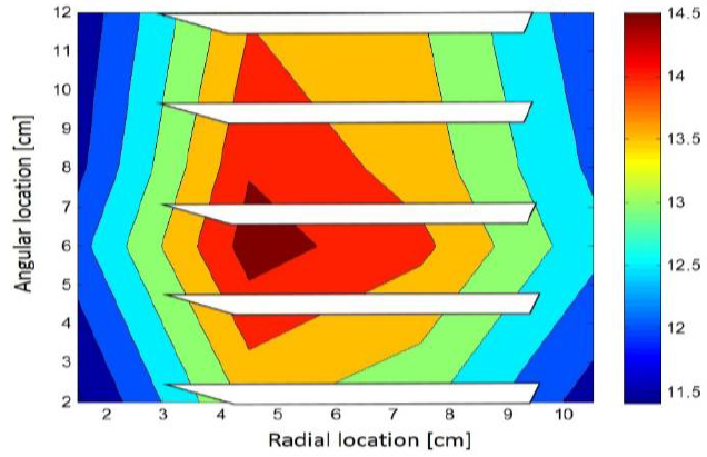
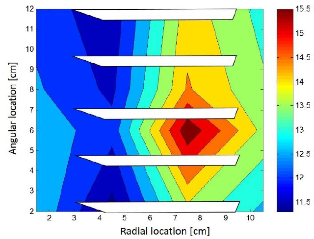
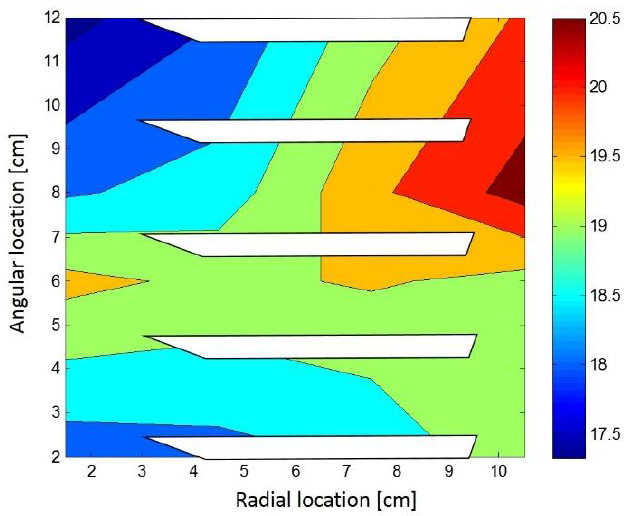
It is the initial damping matrix, φ is the acceptation parameter for the resonance frequencies estimation, ωe 1, ωe 2, ωe 3, ωe 4 are the experimental resonance frequencies shown on Fig. 2. Table 2 and Figs. 13, 14, 15 and 16 show the final results.
Table 2. Final natural frequency estimation error after the recursive adjustment application.
| Frequencies [rad/s] | Error [%] | |
| 1 | 1750.0 | 1.5 |
| 2 | 4105.2 | 2.0 |
| 3 | 5297.9 | 2.5 |
| 4 | 6479.7 | 2.0 |

Figure 13. Error [%] for the first modal shape with the damping parameters adjusted by the recursive algorithm.

Figure 14. Error [%] for the second modal shape with the damping parameters adjusted by the recursive algorithm.

Figure 15. Error [%] for the third modal shape with the damping parameters adjusted by the recursive algorithm.
5. Conclusions
The experimental modal analysis from the set of blades analyzed, was developed through a set of multi-points and simultaneous impact tests, giving four natural frequencies with their corresponding modal shapes in the frequency spectrum of interest for this study case.
Through the authors expertise and the state of the art statement the experimental vibrational modal shapes reported in this document belong to the first four flexible theoretical modes; and their spectral order presentation is also according with the vibration theory if it is considered the free body vibration analysis.
Based on the Fig. 2 and Figs. 3 to 6, it is predictable that set of blades vibrations occurs at high frequencies (1750 to 6500 Hz) with a very low amplitude (less than 14x10-6 m), then because of the rotor rotational speed (7500 rpm = 450,000 Hz) the natural frequencies are excited just in the engine start up or in its pull down; therefore, it has certain that in the steady state speed the set of blades vibrations hardly comes from the flow impacting this solid shape.
The first modal model (without damping adjustment) has a good error of 28.3%, if it is considered that the directly parameters estimation depends on the estimation of a pseudo-inverse matrix; but, to develop more accurate control algorithms the adjustment method proposed is justified, overall if nonlinearities from dynamics are considered.
The recursive algorithm for the model adjustment by modifying the damping parameters has increased the entire mathematical model accuracy to 2.5%, it does not only calculate natural frequencies, it also performs a better modal shapes estimation (see Figs. 13 to 16 and Table 2).
It is important to clarify that the magnitude of the criteria from decision taking from the average of the Eigen values error, in the sixth step of the recursive algorithm; was selected to ensure this algorithm convergence occurs in less than 200 microseconds, to avoid interference with the fastest natural frequency included.
It is concluded also that, because of the naturally of the vibration behavior from the tested set of blades reacts as an underdamped system to a hammer impulse (experimental modal testing); through the inclusion of the damping parameters to the model by the recursive algorithms its results are better than the ones from the analysis without damping consideration.
Modal shapes adjustment is not as good as the frequencies prediction is, so in a future version, the modal shapes error will also have been included into the recursive adjustment algorithm if more accuracy is required.
The validation of the theoretical fundamentals from this proposal for a vibration modal model from the compressor set of blades has been experimentally proven; furthermore, in accordance with the results gotten after the recursive algorithm implementation for the parameters adjustment, the next step for this proposal will be correlate the vibrational behavior from the concerned set of blades with the regulated air flowing in a wind tunnel, with the intention to get an instrumental systems for the air flow characterization by the indirect vibration analysis.


 nueva página del texto (beta)


