


 texto en
  Inglés (pdf)
 Artículo en XML
 Referencias del artículo
 Enviar artículo por email
 Citado por SciELO
  Similares en
SciELO
Similares en
SciELO 
 Permalink
1. Introduction
The main enemy of the durability of concrete structures is the corrosion of steel reinforcement, and this effect is chiefly caused by penetration of chlorides (Cl-) in the concrete mass. When corrosion occurs, it is necessary to repair the structure if we want to use it for more time, otherwise there is a high risk of collapse. The traditional method for structures contaminated by chlorides is the replacement of the structural elements affected by the corrosion process.
Several electrochemical techniques have been successfully used to the protection and remediation of steel corrosion in reinforced concrete structures. All these techniques are based on the lowering of the electric potential of steel (Page, 1992; Mietz, 1998; Andrade, et al, 1998; Tritthart, 1998; Pedeferri and Bertolini, 2000; Bertolini, 2004; Polder, 2005). This effect can be obtained both by connection to a less noble metal, as in cathodic protection (CP) by sacrificial anodes, or by connection to the negative pole of an electric direct current source, as in CP by impressed current (Page, 1997; Pedeferri, 1996; Polder, 1998; Bertolini, et al, 1998; Glass and Chadwick, 1994). The objective of CP is to prevent the initiation of steel corrosion in new structures. On the other hand, temporary techniques are those intended to change the prevailing corrosion conditions of the structures by lowering its chloride content, such as in electrochemical chloride extraction (ECE) ) (Slater, et al, 1976; Vennesland, et al, 1986; Hansson and Hansson, 1993; Elsener, et al, 1993 Thus, it is not necessary to replace the contaminated concrete and, once a sufficient quantity of chlorides has been extracted, the durability of the structure is increased (Slater, et al, 1976; Vennesland, et al, 1986; Hansson y Hansson, 1993; Elsener, et al, 1993). An important aspect regarding the application of this technique is the effect that different bar arrangements may have on the efficiency of ECE when applied to a reinforced concrete structural element. Sánchez de Rojas et al, conclude that the extraction efficiency depends on the reinforcing bar arrangement. A uniform layer set-up favours chloride extraction. It is possible to reduce the chloride content in between two reinforcement layers (Garcés, et al, 2006; Sánchez de Rojas, et al, 2006). On the other hand, different solutions for the external anode have been tested, a Ti-RuO2 wire mesh and a graphite felt fabric, both wrapping the concrete structure with a sandwich-like anodic system consisting of two layers of polypropylene sponge embedding the anodic material. Concluding that if sufficient care is taken with the experimental setup, the efficiency of the extraction with the sandwich-like anodic system may be similar to that obtained with a classical anode immersed in a liquid electrolyte, (Climent, et al, 2006). Finally, also concerning to the external anode, the most important advance in recent years has focused on the study of the viability of using a conductive cement paste (CCP), based on mixes of cement with different carbonaceous materials, as anodic coatings for applications of electrochemical techniques on reinforced concrete, (Pérez, et al, 2010; Carmona, et al, 2015a; Cañón, et al, 2013; Del Moral, et al, 2013; Carmona, et al, 2015b; Climent, et al, 2016; Carmona, et al, 2017; Climent, et al, 2019). For ECE treatments on structural concrete elements, even vertical or of complex shape, the use of a CCP sprayed coating as anode is feasible, because the same efficiency as conventional reference anode (Ti-RuO2 mesh) is obtained (Pérez, et al, 2010). Conductive cement paste is more versatile as anode because the adaptation to various types of surfaces (vertical or more complex shapes) and the possibility of reutilization. One of the most attractive possibilities offered by these anodic conductive layers is the possibility of using a graphite-cement paste anode for combined treatments of EEC plus CP on reinforced concrete elements (Carmona, et al, 2015; Climent, et al, 2019). These treatments would be interesting in cases of structures heavily contaminated with chlorides and continuously exposed to a harsh chloride environment. It has been shown that, in the experimental conditions of this work, the anode is not damaged during the electrochemical chloride extraction step. The application of a previous chloride extraction step allows working with a lower current density at the cathodic protection step, which reduces the risk of damages of the anodic system. The operation conditions of the above mentioned electro-chemical techniques differ in each case (Carmona, et al, 2015a; Cañón, et al, 2013; Del Moral, et al, 2013; Carmona, et al, 2015b; Climent, et al, 2016; Carmona, et al, 2017; Climent, et al, 2019). The typical current density for ECE applications on reinforced concrete elements is in the range 1-5 A/m2, while the total electric charge passed is usually between 1 × 10⁶ and 5 × 10⁶ C/m2. From an electrochemical point of view the current density should be defined as referred to electrode surface, i.e. the surface of the steel cathode. However, in engineering field applications it is sometimes difficult to know the steel reinforcement area. So, many times the current density is referred to exposed concrete surface, which, in the case of anodic overlay systems is equal to the anode area. CP typically applies current density values between 5 and 20 mA/m2, while CPre needs only1-3 mA/m2. Nevertheless, in the case of CP the actual current density needed to effectively protect the steel is higher the higher is the Cl−content of concrete.
Next, the experimental program and main results obtained in the combined and successive application of ECE and CP, without changing the anode, using a conductive cement paste, are exposed. These treatments would be interesting in cases of structures heavily contaminated with chlorides and continuously exposed to a harsh chloride environment.
2. Experimental procedure
2.1 Methodology
The specimens dedicated to testing the CP or, ECE + CP were prepared with concrete admixed with Cl− ions. Table 1 indicates the nomenclature of the specimens and the electrochemical treatments applied to each one. It must be stressed that all specimens included in Table 1, even those that were not given any of the electrochemical treatments (R and P), were subjected to the same salting regime during the 24 weeks period that lasted the CP treatment: 65 ml NaCl 0.5 M weekly sprayed onto the concrete or anodic overlay surface, in order to simulate the continued chloride contamination due to exposure to a very aggressive environment as mentioned above.
2.2. Reinforced concrete specimens
The specimens were prism-shaped reinforced concrete elements, with a dimension of 18 × 18 × 8 cm3, which were reinforced by a grid 16 × 16 cm2 composed of six steel bars (5 mm diameter) welded symmetrically forming squares of 5 cm side, and placed 2 cm under the anode, Fig. 1.
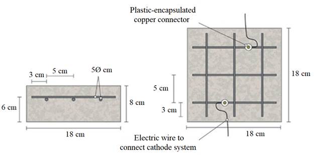
Figure 1 Sketch of reinforcement of samples and connection of the cathodic system (steel reinforcement). Adapted from (Carmona, et al, 2015).
The concrete dosage was as shown in Table 2. One mix was prepared: containing 2% Cl− relative to cement mass for the specimens used in cathodic protection (CP) applications or combined treatment (ECE + CP), see Table 1. Once the formwork was removed, the specimens were moist-cured at 95-98% relative humidity (RH) for 28 days. The characteristics of the hardened concrete were as follows: compressive strength 37.8 N/mm2 (AENOR, 2009), porosity 11.1% (UNE, 2014), and bulk density 2.38 T/m3 (UNE EN, 2009).
Table 2 Concrete dosage for preparation of the test specimens
| Material | Dosage |
|---|---|
| Portland cement CEM I 42,5 R | 250 kg/m3 |
| Water/cement ratio (w/c) | 0,65 |
| Limestone aggregate | 1890 kg/m3 |
| Superplasticizer | 2,50 kg/m3 |
| NaCl | 3,3% (2% Cl- relative to cement mass) |
Fig. 1 also shows the system used for connecting the reinforcement (cathode system) to the negative pole of the electric power source, through plastic isolated copper connectors screwed to the rebar.
2.3 Common experimental details of the electrochemical tests
All the electrochemical tests were performed using a CCP anode. The anodic overlay system was prepared by hardening a graphite-cement paste (GCP) obtained by mixing graphite powder and Portland cement at 50%-50% in mass. Water to solid mix ratio was 0.8. The resistivity of the graphite-cement paste was measured through the four-probe method (Galao, et al, 2014). Secondly, a 2 mm thick layer of this paste was applied on the surface of each specimen, and then all of them were moist cured for 10 days. After that, two grooves were performed lengthwise onto the anodic overlay, without reaching the concrete surface, in order to receive both graphite rods to connect to the positive pole of the electric source. To finish up, these rods were overlaid with graphite-cement paste in order to join with the anode system perfectly but avoiding any contact between graphite rods and concrete.
The measurements of steel corrosion potential (Ecorr) and all the single electrode potentials, were performed using Ag-AgCl reference electrodes. These electrodes were housed in respective holes drilled from the exposed surface of the concrete specimen (that bearing the graphite-cement anode) to the vicinity of the rebar, Fig. 2. For this purpose, the holes were sheathed with a plastic tube, and filled with a KOH 0.2 M aqueous solution, trying to approach the physical-chemical conditions of the concrete’s inner pore solution
Two of the salted specimens were used only for determining the efficiency of the ECE process. Concrete cores were extracted from them, and their chloride content profiles were determined, in one case before and in the other case after ECE. The ECE efficiencies were calculated as the percentages of reduction of the initial chloride content. Obtaining the chloride content profiles before and after the ECE trials allowed calculating the local and overall efficiencies. The Cl− profiles were measured following essentially RILEM recommended procedures (Vennesland, et al, 2013). Cylindrical concrete cores, 95 mm diameter and 20 mm height (up to the rebar depth), were extracted. From these cores, concrete dust samples were obtained by grinding thin (2 mm thick) successive parallel layers to the exposed surface. In this way 10 concrete dust samples were gained from each core, thus allowing the obtention of sufficiently detailed chloride content profiles. The determination of the samples’ acid soluble chloride contents was carried out by potentiometric titration, (Climent, et al, 1999; Climent, et al, 2004). All the chloride content values are expressed in this work as % Cl- relative to cement mass.
The ECE treatments were applied galvanostatically with 2 A/m2 of current density (relative to concrete or anode surface) and 1.5 MC/m2 of charge density relative to concrete surface ((2.6 MC/m2 relative to steel surface). The external electrolyte in contact with the anode was tap water.
The CP treatments were applied galvanostatically with 15 mA/m2 of current density (relative to concrete or anode surface) (25.5 MC/m2 relative to steel surface). Both techniques, ECE and CP, were applied under laboratory conditions (20ºC and RH 60%). The potential data were recorded using a data acquisition system.
The application of CP consisted of two phases:
Phase 1. First 24 weeks. The aforementioned treatment CP was continuously applied during the first 13 weeks. Then, the current was switched off for 4 weeks and after that, treatments were resumed to the end. Chloride contamination was continuously applied, even during the switch off periods.
While applying the CP treatments some electrochemical parameters were measured. During the current passing periods the feeding voltage of each specimen, Efeed, was obtained as the potential difference between cathode and anode; and the individual anodic and cathodic potentials, Ea and Ec, respectively, were measured against the reference electrode Ag/AgCl. Finally, in order to check the efficiency of CP as maintainer of protection conditions of steel, the “100 mV decay” criterion was used, as is specified in ISO 12696:2012. This criterion has been also extensively employed for this purpose by several researchers (Glass, et al, 2001; Liu and Shi, 2012; Dugarte, et al, 2015; Christodoulou, 2010). The method consists in obtaining the 4 h potential decay (E decay), that is the difference between E c 4h (the value of E c 4h after the current switch off), and the instant-off cathodic potential E c io, which in this case was measured 1 s after the current switch off. The minimum value of the 4 h depolarization must be 100 mV for an adequate corrosion protection of steel. The values of E c io were monitored with an automatic data logger able to obtain and record 500 measurements in 6 s, after the current switch off.
Once the 24 weeks processes were fulfilled, cores were extracted from all specimens of Table 1, and their respective Cl− content profiles were obtained. This was done with the purpose of evaluating the net effect of the electrochemical treatments on the Cl− ion uptake by the reinforced concrete specimens during the continued exposure to a very aggressive environment.
Phase 2. At the end of Phase 1 it was observed that all the specimens had lost the steel protection condition, evidenced by Edecay values lower than 100 mV. Then, it was decided to start this second phase with the objective of recovering the protection conditions of steel by adjusting the current density of the CP treatments. The procedure was to increase progressively the current density during 4 weeks, starting with a value of 20 mA/m2, until obtaining the protection conditions (??Edecay≥100 mV.
3. Results and discussion
3.1. Application of ECE
Two of the reinforced concrete specimens were subjected to an ECE treatment before starting the first phase of the CP treatments. Once finished the ECE process with the settled parameters, Cl− content profiles were obtained, corresponding to the states before and after the ECE treatment. The local ECE efficiencies, understood as percentage of Cl− content removed, are plotted in Fig. 2. The average of removed Cl− was 51% of the initial content, i.e. the residual Cl−content of concrete after ECE was approximately 1% referred to cement mass. This indicates a good performance of the ECE process applied on a conventional ordinary Portland cement concrete with the GCP anodic overlay system, for a relatively low charge density of 1.5×10⁶C/m2 relative to concrete surface. This result can be compared to the 41% efficiency obtained for a very similar reinforced concrete element, with the same initial amount of Cl−, subject to an ECE treatment, using a Ti-RuO2 mesh anode, and passing a total charge density of 1 MC/m2 relative to concrete surface (Pérez, et al, 2010).

Figura 2 Choride concentration profiles before ECE (initial) and after ECE (final) and local efficiencies of the extration process. Adapted from (Carmona, et al., 2015)
3.2. First phase of electrochemical treatments
In this section we describe the results of tests carried out to investigate the performance of the CCP anodes during protective electrochemical treatments to reinforced concrete elements affected by steel corrosion due to chloride contamination, such are CP, and combined treatments of ECE + CP.
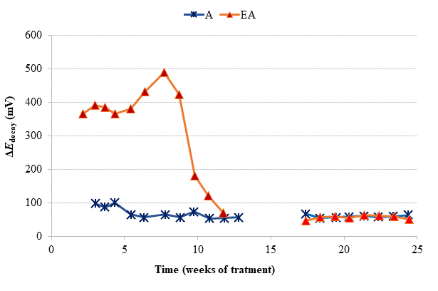
Figure 3 Evolution of ΔE decay during the CP treatments. A: CP; EA: ECE + CP. All of them subjected to Cl− contamination during the 24 weeks. The electrochemical treatments were interrupted between week 13 and week 17. Adapted from (Carmona, et al, 2015).
To verify the effectiveness of CP treatments for protecting steel from corrosion, the “100 mV decay” criterion (ISO, 2012) was used, as stated in Section 2.3. Fig. 4 shows the evolution of the ΔE decay values for the specimens in Table 1, during the 24 weeks experiments. The ΔE decay values of the A specimen, treated only with CP, practically never reached the threshold value of 100 mV. It seems that a 15 mA/m2 current density was not sufficient to provide protection to steel in such harsh conditions: initial Cl− content of 2% plus the continued salting regime (65 ml NaCl 0.5 M weekly sprayed onto the anodic overlay surface). Regarding the EA specimen (ECE + CP), the protection conditions of steel were kept during 11 weeks because of the current circulation, despite external Cl− loading. Cathodic protection of 15 mA/m2 current density, relative to concrete surface, was able to keep protective conditions for the steel reinforcement if the initial Cl− content of the specimen was about 1%.
So, in the case of the specimen with initial Cl− content of about 2%, a higher current density would be needed for reaching the protection conditions (Pedeferri, 1996). These observations corroborate the main hypothesis of the present research, i.e. in cases of reinforced concrete structures with a high Cl− contamination subject to very harsh chloride environments, it would be advantageous to apply successively an initial ECE treatment to reduce the Cl− content, and then maintain protective conditions to steel through a continuous CP treatment without the need of using a too high CP current density, which could eventually impair the performance of the anodic system (Carmona, et al, 2015). These combined treatments, ECE + CP, would be more conveniently implemented with the CCP coatings since the same anode can serve both for the ECE and for the CP treatments.
Table 3 Final averaged chloride contents (expressed in % Cl− relative to cement mass) at the end of the 24 weeks of exposure to a severe Cl− load.
| Specimen | Initial Cl− content (% ref. cem. mass) | Electrochemical treatment previous to the 24 weeks first phase | Electrochemical treatment previous to the 24 weeks first phase | Final averaged (*) Cl− content (% ref. cem. mass) |
|---|---|---|---|---|
| P | 0% | - | - | 4,93% |
| R | 2% | - | - | 6,08% |
| ER | 2% | ECE | - | 4,26% |
| A | 2% | - | PC | 5,39% |
| EA | 2% | ECE | PC | 3,41% |
(*) The final Cl− content was calculated as the mean value of those found in the Cl− content profile determined through the concrete cover zone (20 mm width)
At the end of Phase 1 all the reinforced concrete specimens had reached a very high degree of Cl− contamination, as can be appreciated in Table 3. Nevertheless, some comparisons can be done on the behavior of the different cases. For instance, specimens treated with ECE + CP (EA) during Phase 1, have experienced less Cl− ingress than the reference specimen ER, which after the ECE trial was left untreated during the phase 1. This represents a further evidence of the “chloride barrier effect”, mentioned by Pedeferri (Pedeferri, 1996) , as one of the beneficial secondary effects of CP, as the polarity of the electric field induces a repellent effect of the negative ions, thus reducing the chloride uptake by concrete in a harsh chloride environment.
3.3. Second phase of electrochemical treatments
Given that after the 24 weeks of treatments of phase 1, including rest periods between the 13th and 17th weeks, the steel reinforcements in all concrete specimens had completely lost their protection conditions, and having been demonstrated that a CP of 15 mA/m2 was unable to restore the protective conditions (Fig. 4), the Phase 2 was started. The external Cl− load was discontinued since all the specimens had reached very high Cl− contents, see Table 4. In these conditions, CP was applied with higher current densities. The question was if it would be possible to recover the protection conditions of steel by increasing the current density to the appropriate value. In the beginning of this last phase, the current density was set at 20 mA/m2. After 4 weeks in operation the threshold value of 100 mV was not reached, i.e. the protection conditions were not obtained, Fig. 6. Neither success was obtained in a second attempt at 25 mA/m2 (data not shown in Fig. 6). Finally, a third step of 40 mA/m2 was set. In this case, after 4 weeks, the rule of 100 mV of ΔE decay was achieved for EA and A specimens.

Figure 4 Evolution of ΔEdecay during phase 2 of CP. First step of 4 weeks with 20 mA/m2 of current density, and third step with 40 mA/m2. Adapted from (Carmona, et al, 2015).
Moreover, protection conditions were verified with the measurement of depolarization potential difference values 7 days after switch off [39]. In fact, more than 150 mV of ΔE decay was reached after 7 days (209 mV for EA).
4. Conclusions
The results of this work point out that it is possible to use a graphite-cement paste, overlaid on the surface of a reinforced concrete element, as the anode for successive treatments of electrochemical chloride extraction, to reduce the chloride content and then cathodic protection to maintain protective conditions for the steel reinforcement.
It is possible to recover protective conditions against corrosion of steel reinforcement in concrete by applying a combined treatment of ECE followed by a continuous CP treatment. The current density value of the CP step must be set at the proper value, according to the residual chloride content in concrete.

