


 texto en
  Inglés (pdf)
 Artículo en XML
 Referencias del artículo
 Enviar artículo por email
 Citado por SciELO
  Similares en
SciELO
Similares en
SciELO 
 Permalink
1. Introduction
The use of solar energy has become a promising method to reach energy efficient solutions throughout the last century. Improving the thermal properties of building members will contribute to the efficient use of energy by preventing heat gain/loss through the building envelope. More over thermal comfort became important with development of panel and thin building envelope systems due to their low thermal mass. Phase change materials (PCM) are favorable materials for thermal applications because of their large contribution to the thermal mass of a building and thus providing “inertia” against temperature fluctuations.
Sustainability has become a goal for global development and for the effective use of reliable, sustainable and modern energy. This goal has been revealed among the objectives of United Nations (UN) 2030 (United Nations, 2015; Esseghir and Khouni, 2014).
On the other hand, energy consumption in the world is increasing significantly. This rise in consumption is also causing environmental problems. In the last two decades this increase has reached 30% (Sharifi et al., 2017; Chen et al., 2017; Chwieduk et al., 2003; Papadopoulos et al., 2002; IEA, 2016).
Considering that 60% of energy consumption is consumed by buildings due to heating and cooling operations, it should be considered that reducing this consumption will make a significant contribution to global energy consumption. Passive air conditioning methods can be applied to reduce energy consumption in buildings. Passive air conditioning technologies can be used in conjunction with traditional methods to create hybrid systems (Geetha and Velraj, 2012; Akeiber et al., 2012).
PCMs are materials with high latent heat capacity. With PCMs, it is possible to store high amount of energy in order to control the heat fluctuations in the indoor environment and to increase comfort (Mehling and Cabeza, 2008; Souayfane et al., 2016). When the ambient temperature rises above the melting temperature of the PCMs, the PCM performs a phase conversion from solid to liquid. During this conversion heat accumulates at high temperatures. It also solidifies when the temperature falls below the melting temperature of the ambient temperature and releases the stored heat. This process prevents high fluctuations in ambient temperature. PCMs stay at a nearly constant temperature during phase changes to prevent over-heating and cooling of the environment (Sharifi et al., 2017; Raoux and Wuttig, 2009).
With utilization of PCM in building materials, cooling and heating loads of the buildings can be reduced. Due to the high latent heat storage capacity of PCMs, which means a greater heat storage per unit volume than other building materials (Sharma et al., 2009), thermal inertia of the building that uses PCM integrated building materials will be greater (Singh Rathore et al., 2020). Microencapsulation, which is the process of enclosing the micron size particles of solid, liquid and gasses in an inert shell, is one of the methods that can be used to integrate PCM into other materials. Microencapsulated PCMs have been used in many researches to enhance the thermal performance of building materials (Barreneche et al., 2013; Arce et al., 2012; Thiele et al., 2015, Su et al., 2012; Borreguero et al. 2014; Li et al., 2019; Tuncel and Pekmezci, 2018). Although there is a common conclusion on the success of the PCMs on thermal performance enhancement, their effects on the mechanical properties of the building materials which they are integrated in, still need further examination for reliable applications.
2. Experimental study
In this study, experiments were carried out to determine the mechanical and thermal properties of cement composite panels containing PCM. Calender extrusion which is a sustainable production method has been used in the production of panels. Panels with PCM content of 2.5% and 5%, and panels which are not containing PCM (0%), were produced in the production using the calender extrusion system. The schematic representation of calender extrusion fiber reinforced cementitious panel production system is given in Figure 1.

The dimensions of the produced samples were 60x120x2.5 cm. The ambient environmental conditions were 18℃ temperature and 65% relative humidity. The produced panel specimens were brought to the dimensions necessary for the experimental study, and experiments were carried out. Discrete glass fibers were used in the production of composites. Tests were carried out at 18℃ ambient temperature.
Cement was White Cement obtained from Cimsa Cement Factory Turkey. A polycarboxylate based superplasticizer, which was obtained from SIKA Turkey, was used for production of specimens. The properties of Cimsa White Cement are given in Table 1. CEM-FIL Anti-Crak HP 74/12 chopped glass strands were used as the reinforcement. The manufacturer-supplied properties of the fibers are presented in Table 2. The properties of PCM (provided by the manufacturer) are presented in Table 3.
Table 1 Properties of cement
| Property | Value |
|---|---|
| Setting time, initial (minute) | 115 |
| Le chatelier opening (mm) | 1.0 |
| Compressive strength, 2 days, MPa | 37.0 |
| Compressive strength, 28 days, MPa | 60.0 |
| SO3 (%) | 3.45 |
| Unsoluble residue (%) | 0.16 |
| Ignition loss (%) | 3.10 |
| Cl- (%) | 0.011 |
Table 2 Properties of glass fiber.
| Fiber Length | 12 mm |
| Aspect ratio (length / diameter) | 74 |
| Filament Diameter | 14 - 19 μm |
| Loss on Ignition (%) (ISO 1887: 1995) | 0.80 - 2.00 |
| Moisture (%) (ISO 3344: 1997) | 0.50 max |
| Specific Gravity | 2.68 g/cm3 |
| Material | Alkali Resistant Glass |
| Chemical Resistance | very high |
| Modulus of elasticity | 72 GPa |
| Tensile Strength | 1700 MPa |
Table 3 Properties of PCM
| Product type | Powder |
|---|---|
| Melting point (approx. in °C) | 23 |
| Overall storage capacity (approx. in kJ/kg) | 135 |
| Latent heat capacity (approx. in kJ/kg) | 100 |
In design of the composite panels, two different PCM amount were used (2.5% and 5.0% of total mass). A plain mixture that did not include PCM was also produced for comparison. In all mixtures, the fiber ratio was used as 2% of total volume. Water / cement ratio is kept as 0.40. The workability of the mixtures, which is suitable for calender extrusion, is provided by superplasticizer and viscosity modifier. The mix proportions of the mixtures used in the study are given in Table 4.
3. Results and discussion
3.1 Thermal conductivity and mechanical properties
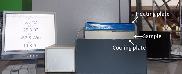
The thermal conductivity tests were conducted according to ISO 8301:1991 using a heat flow meter apparatus (Ahlborn) on plain and PCM composites. Figure 2 shows thermal conductivity test setup. Specimens with dimensions of 350 x 350 x 25 mm were used for the thermal conductivity measurements and were kept in saturated lime water at 21±1℃ temperature for 28 days. Specimens were dried at 60℃ until they achieved constant weight to avoid any moisture-based test error. Testing began when the specimen came to room temperature. Determination of the thermal conductivity was performed at a steady state condition with a mean temperature of +10℃ at the center of the cross-section of sample.
The thermal conductivity of the panels were 0.33 W/mK, 0.31 W/mK and 0.29 W/mK for panels including 0%, 2.5% and 5% PCM by total mass respectively. Although the ratio of PCM, leads to a change in the thermal conductivity values, this change is not significant when evaluated from the viewpoint of heat insulation.
The mechanical properties of the composites were based on the 28-day uniaxial compressive strength test and the simple beam four-point bending test. Compressive strength tests were conducted on 40 mm cube specimens. For flexural tests, beam specimens of 45 mm width and 25 mm height were used. The length of the beam was 350 mm while the span length was 300 mm. A closed-loop testing machine (MTS Criterion 5500) was used in both tests and load-deflection curves were generated in the flexural tests. The specific fracture energy values (Wf) of the specimens were also determined in accordance with the recommendation of the RILEM 50-FMC Technical Committee (RILEM TCS, 1985). Tests were conducted at 18℃. Five individual specimens were tested for each group.
Figure 3 shows the results of the compressive strength test. It is clear from the figure that as the PCM ratio increases, the compressive strength of the matrix decreases. When the variation of the compressive strength values with the PCM ratios of matrix is examined, the compressive strength of the matrix is decreased by 7.5% and 10% when the PCM is used by 2.5% and 5%, respectively.

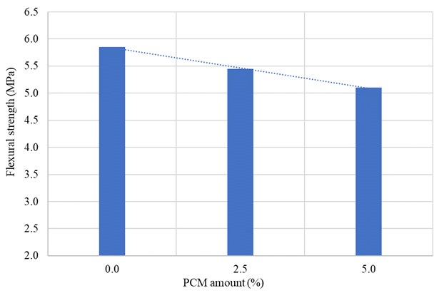
Figure 4 shows the variation of flexural strength values with PCM amount. It is clear that flexural strengths decrease as the amount of PCM in the mixture increases. When the PCM content is 2.5% and 5%, the flexural strengths decrease by 7% and 13%, respectively.
Figure 5 shows the variation of specific fracture energy values with PCM amount. The specific fracture energy values increase as the PCM amount of the mixture increases in contrast to the strength values. The specific fracture energy increase was 31% and 40% for PCM ratios of 2.5 and 5%, respectively. This increase in specific fracture energy values can be attributed to an increase in deformation capacity. As the amount of PCM in the mixture increases, the ductility of the composites also increases due to the specific fracture energy value.

3.2 Microstructure
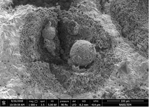
The micrograph of the microencapsulated PCM in the cement matrix is shown in Figure 6. When we look at the Figure 6, it can be said that the microencapsulated PCM provides good bonding with the cement matrix and there are no cracks at the interface. However, it is observed that the PCM retains its spherical shape. This shows that microencapsulated PCMs during mixing, processing and curing can be used without deterioration.
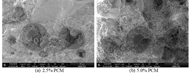
In the Figure 7, the distribution of microencapsulated PCMs in the cement based matrix is shown in the case of using PCM at different ratios.
Figures 7a and 7b show SEM images of mixtures containing 2.5% and 5% PCM, respectively. It is clear that the microencapsulated PCMs are placed closer to each other at 5% use, but the PCM capsules do not contact each other while preserving the integrity of the mortar phase there between.
3.3 Thermal heat storage performance
The inner walls of two rooms of equivalent size were covered with the produced panel samples and the temperature changes in the rooms were monitored. Panels without PCM were applied to one of the rooms while panel samples containing PCM containing 5% were applied to the other room. In order to obtain the best performance from the PCM, measurements were made in the equivalent rooms having 50 m3 volume built in the main laboratory building. The main laboratory's air conditioning was shut down for four days during a vacation and the temperature in the main laboratory was allowed to fluctuate depending on natural conditions. In this process, the maximum temperature in the laboratory reached 28℃ during the daytime hours and the minimum temperature remained at 15℃ during the night hours. The maximum fluctuation in the room was measured as 3℃ in the room where PCM-free panels were used, while 1℃ was used for the room where PCM including panels were used.
4. Conclusions
Within the scope of this experimental study, the following conclusions can be drawn;
The cementitious composite panels including PCM’s are promising in terms of mechanical properties. Although PCM usage causes decrease on strength values, this decrease is not dramatic to prevent the use of the composite panels in situ. Moreover, PCM usage helps to increase the specific fracture energy values.
Although the ratio of PCM used leads to a change in the thermal conductivity values, this change is not significant when evaluated from the viewpoint of heat insulation.
The maximum fluctuation in the room was measured as 3℃ in the room where PCM-free panels were used, while 1℃ was used for the room where PCM including panels were used.

