Introduction
The splitting of d-orbitals is an important concept to be learnt not only in India but students all over the world. Further, any good university library devoid of standard books such as Concise Inorganic Chemistry' by J .D .Lee and 'Theoretical Inorganic Chemistry' by Marion Clyde Jr. Day and Joel Selbin, is difficult to imagine. Since the d-oribtal splitting is not explained explicitly in these books, this short pedagogical communication which explicitly explains the d-orbital splitting by the use of a simple rule of thumb is useful for the teachers and the taught, across the globe.
The following paragraph (verbatim from J.D.Lee[1]) explains the splitting of d-orbitals in octahedral complex.
In an octahedral complex, the metal is at the center of the octahedron and the ligands are at the six corners. The directions x, y and z point to the corners of the octahedron. The eg orbitals (dx2-y2) and (dz2) are directed along the axes and t2g orbitals (dxy, dxz, dyz) point in between the axes x, y and z. It follows that the approach of six ligands along x, y, z, -x, -y and -z directions increase the energy of dx2-y2 and dz2 orbitals which point along the axes much more than dxy, dxz, and dyz orbitals which point in between the axes. Thus under the influence of an octahedral ligand field the d-orbitals split into two groups of different energies as shown in Figure A[2].
Discussion
The logical question which follows, and which students often ask is, "Why is the energy of dx2-y2 and dz2 orbitals (eg set of orbitals) which point along the axes much more than that of the dxy, dxz , and dyz orbitals (t2g set of orbitals) which point in between the axes?' This question was asked by many freshmen engineering students (non-chemistry discipline).
The above question can be answered from symmetry considerations alone, using group theory, but the answer from this standpoint is difficult for freshman engineering (non-chemistry discipline) and pre-university students to comprehend. The following 'rule of thumb', while not a full answer appropriate at a higher level of education, is a pedagogically useful way of helping students at this level to understand this phenomenon.
Attraction is associated with lowering of energy and repulsion is associated with increase of energy
Since the eg orbitals are along the axes and the approach of negatively charged ligands is also along the axes, appreciable repulsion occurs between the electrons of eg orbitals and the negatively charged ligands. As already stated, repulsion is associated with increase of energy, hence eg orbitals have increased energy. Whereas, the t2g orbitals are between the axes and the approach of ligands is along the axes, the repulsion between electrons of the t2g orbitals and the negatively charged ligands is less, and therefore the energy of t2g orbitals is lower than that of eg orbitals.
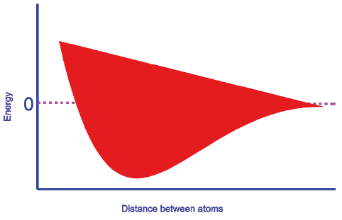
This simple 'rule of thumb' can also be useful in teaching other concepts in ways that are accessible to students. In the same book [1], while explaining the linear combination of the atomic orbitals of hydrogen atoms, a plot of energy versus distance between the atoms of Ψ(g) molecular orbital (Figure B) is presented, where g of Ψ(g) stands for gerade. The plot is depicted, but the explanation for the trend of the curve is not explained. The same is the case with another textbook [5] written for freshman engineering (non-chemistry discipline) education. This trend can again be explained with the help of our rule of thumb (especially for non-chemistry freshman audience).
Consider Ψ(g) in the above plot. The two 1 s orbitals of different H atoms approach to form a molecular orbital. As the orbitals approach to form a bond, the electron of the H atom of one of the orbitals which was initially under the influence of one nucleus, is now under the influence of two nuclei. This results in more electrostatic attraction and as a consequence lowering of energy (attraction is associated with lowering of energy). The state of affairs is the same with other electron in the other H atom. Thus, the fall in the Ψ(g) curve. After the curve reaches a minimum (here the bond distance is equal to bond length), the energy starts increasing. The reason for this is that if we further push the orbitals (after the minimum point is reached), repulsion between the nuclei commences and as a consequence the energy increases (repulsion is associated with increase in energy).
This thumb rule also explains why Δo (the difference in energy between two levels t2g and eg levels in octahedral field) increases on descending a group of transition elements (Table 1).
The above table is again from reference [1]. The book only says that Δo (the difference in energy between two levels t2g and eg levels in octahedral field) increases on descending a group of transition elements. But it does not explain why it increases down the group. As you go down the group, the distance of d-orbitals from the nucleus increases. In other words the d-orbitals are more available for the approaching negative ligands, hence more repulsion between the electrons of the d-orbital and the negatively charged ligands (a point to be noted is that if the ligands are neutral, the negative end of the dipole molecule is directed towards the metal ion). More repulsion is associated with gain of energy hence the more Ao as one goes down the group. Again this rule of thumb helps in understanding this point.
The splitting of d-orbitals in tetrahedral ligand field is explained well in the book[1], but again the correct reason for why the t2g is above the barycenter and eg below the barycenter is not given explicitly. The splitting is explained as follows (verbatim from J.D.Lee [1]) as follows:
A regular tetrahedron is related to a cube, with an atom at the center, and four of the eight corners occupied by ligands. The directions of axes X,Y, and Z point towards the faces of the tetrahedron as shown in Figure C[1].
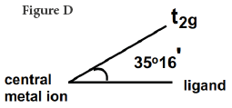
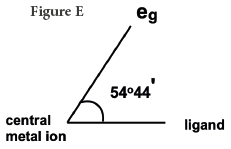
The direction of approach of the ligands does not coincide exactly with either the eg or the t2g orbitals. The angle between an eg orbital, central metal and the ligand is half the tetrahedral angle = 109o28'/2= 54o44'. The angle between a t2g orbital, central metal and the ligand is 35o16'. Thus the t2g orbitals are nearer to the directions of the ligands than eg orbitals The approach of the ligands raises the energy of both sets of orbitals, but since t2g are closest to ligands they are raised most.
The discussion in the foregoing paragraph from J.D. Lee [1] can be made more lucid or comprehensible by applying our rule of thumb. Since the t2g orbitals are closer (Figure D) to the ligands (35o16') than eg (Figure E) orbitals (54o44') the repulsion between the electrons of t2g orbitals and the ligands is more, hence the energy is raised higher; it does conform to our rule of thumb, repulsion is associated with the gain of energy.
To comprehend this simple rule of thumb, one can visit the basics of physics by considering the following example:
The columbic potential energy (E) of two charged particles 'q1' and 'q2' separated by a distance 'r' is given by the equation
For oppositely charged particles, that is when there is attraction, E has -sign. As 'r' decreases that is when oppositely charged particles come closer, E becomes more negative in other words energy is lowered. Thus attraction is associated with lowering of energy.
For charges with same sign that is when there is repulsion, E is positive. As 'r' decreases the positive E value increases, in other words energy is increased. Thus repulsion is associated with increase in energy.
Another important point regarding this rule of thumb is that its use is applicable when pure classical model is applied. So this article would find a place for pre-university and freshman students of engineering (non-chemistry discipline).
Conclusion
This simple rule of thumb is pedagogically valuable to explain to students why the energy levels of a certain set of d-orbitals are above the barycenter and another set of d-orbitals is below the barycenter (at least for freshmen non-chemistry discipline and pre-university students). Neither the very old standard books [1,3] nor the latest books [4,5] clearly explain the reason for splitting of d-orbitals and this simple approach helps to enhance students' understanding. Further, this simple rule of thumb is also pedagogically valuable while explaining the plot (Figure B) while teaching linear combination of atomic orbitals. This plot was neither explained in the old standard book written by J.D Lee [1] nor the latest book written [5] for freshman engineering audience.


 nueva página del texto (beta)


