1 Introduction
Modern automobiles use several sensors fabricated with microtechnology that can provide a better performance, comfort and safety. These sensors have advantages such as low cost, small size, dynamic range wide and high resolution. However, these sensors need electrical power for their performance, which could be supplied with energy harvesting devices (Wei and Jing, 2017).
These devices are an option to replace conventional batteries used in many electronics devices (Selvan and Ali, 2016; Paradiso and Starner, 2005). The energy harvesting devices can be classified considering their main transduction methods: piezoelectric, electrostatic and electromagnetic (Blokhina et al., 2016). For instance, electrostatic transduction allows integration of energy harvesting devices with microelectromechanical systems (MEMS). These devices require aligned electrodes patterns and any slight misalignment or rotation between them alters the overall performance. On the other hand, electromagnetic energy harvesting devices do not need external voltage sources and can operate at low frequencies; although, they need the deposition of magnetic layers using postprocessing. The third option is the piezoelectric transduction that is suitable for MEMS devices fabrication and does not demand external voltage sources and precise alignment. The piezoelectric vibration energy harvesting (PVEH) devices are potential alternative sources to supply electrical energy to sensors of modern and future automobiles. Yu et al. (2014) developed a PHEV device formed by a piezoelectric cantilever array with an integrated large silicon proof mass. This device (footprint size of 11 x 12.4 mm) generates 66.75 μW at its resonant frequency of 234.5 Hz with an optimal resistive load of 220 kΩ and a vibration acceleration of 5m/s2. However, this device has a resonant frequency that exceeds the peak operating frequency (close to 200 Hz) of an automobile engine.
Lu et al. (2015) fabricated a PVEH device (footprinze size of 6 x 6 mm) composed by a micromachined silicon disk supported by three sandwiched piezoelectric springs.
This device has a resonant frequency less than 20 Hz and a power of 0.57 μW under an acceleration of 0.1g; although, this acceleration amplitude is lower than that of automobile engines. Tang et al. (2016) designed a PVEH device composed by a microcantilever (footprint size of 12 x 6 mm) with piezoelectric and phosphor bronze layers and a proof mass of silicon and tungsten.
This design can provide an open-circuit output voltage of 61.2 V when the vibration acceleration is close to 7.0g and the resonant frequency is 100.8 Hz. Elfrink et al. (2011) reported a PVEH device with high power of 489 μW under sinusoidal input vibrations at frequencies about 1 kHz for automotive applications; nevertheless, it needs a vacuum packaging.
Most of these PVEH devices operate with vacuum packaging and do not performance at resonant frequencies and vibration accelerations close to those of automobile engine. In addition, they are developed through complex fabrication processes or post-processing. In order to overcome these disadvantages, we design a PVEH device composed by two silicon cantilevers with trapezoid shape, a PZT layer and two silicon proof masses.
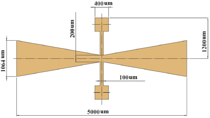
This design is based on the PiezoMUMPs fabrication process of MEMSCAP (Cowen et al., 2014). Our device operates at resonant frequency (207.8 Hz) under a vibration acceleration (12.0 m/s2) close to that of automotive engine. The proposed device has a compact structure (5000 x 2400 μm of footprint size) and does not require a vacuum packaging and post-processing.
It can generate a power of 0.378 μW with a resistive load of 10 kΩ and quality factor of 30.9. A proposed devices array can be series connected to get higher power.
The work is organized as follows: section 2 describes the operation principle of the PVEH device. Section 3 depicts the FEM models of the PVEH device to predict its mechanical and electrical performance. The results and discussions of the finite element method (FEM) models are indicated in section 4. Section 5 shows the conclusions and future researches.
2 Operation Principle
The design of the MEMS-PVEH device considers two cantilevers with trapezoidal shape (2500 ×1064 × 9 μm) that includes a lead zirconate titanate (PZT-5H) film (1 μm thickness) deposited on a silicon layer (8 μm thickness) and two silicon proof masses (400 μm thickness). Figure 1 shows the main components of the proposed device, which are based on the piezoMUMPS® fabrication process. Also, it shows the connection of the resistive load with the PZT-5H film, which is necessary for the finite element analysis. Figure 2 shows the dimensions of the PVEH device. Due to a vibration acceleration with orthogonal direction to the device upper surface, the two cantilevers will have out-of-plane deflections (see Fig. 3).
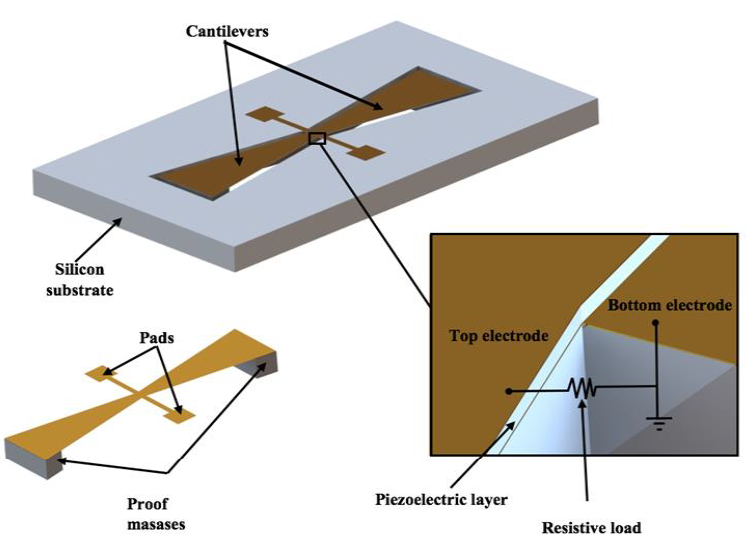
Fig. 1 Design of a MEMS-PVEH device formed by two silicon cantilevers, a PZT-5H film and two silicon masses
It will cause deformations of the PZT-5H film, generating output voltages between its upper and bottom electrodes. Thus, when this device is under environmental vibrations then the two cantilevers oscillate due to the inertia of their large proof masses. The generated voltage by the device will depend of the deformation magnitude of the PZT-5H film, which is related with acceleration and oscillation frequency. To increase the deformations of the cantilevers and the generated voltage, they must operate at resonance with a flexure vibration mode.
2.1 Quality Factor
The proposed PVEH device operates at atmospheric pressure and its main energy loss mechanism is due to the air damping.
This damping can be calculated using the Bloom model (Blom et al., 1992):
with:
where f r is the resonant frequency of the device, ρ p the density of the silicon, b, h and L are the width, thickness and length of the cantilever, respectively, and μ and ρ a are the viscosity and the density of the air, respectively. Because the cantilever surface has trapezoidal shape, its average width b is approximated as the half of the sum between the long and short base.
The damping ratio (ζ) of the cantilever is the reciprocal of twice its total quality factor (Q):
For our PVEH device operating at atmospheric pressure, its total quality factor is approximately equal to that related with the air damping of the cantilevers.
3 Finite Element Models
MEF models of the PVEH device are developed to predict their deflections, main stresses and output voltage at resonance and under a vibration acceleration. These models (see Fig. 4) are implemented through ANSYS® software using the Solid226 element type with keyopt(1) = 1001 for piezoelectric materials. Table 1 depicts the mechanical properties of the materials used in the FEM models. In these models, the PZT-5H film is assumed as anisotropic material with the elastic, piezoelectric and relative permittivity matrices indicated into Eqs. (5-7) (Jiashi, 2006). Moreover, we employ the circu94 element type to represent an electrical resistive load (10 kΩ) connected to bottom and upper faces of PZT-5H film (see Fig. 1). This element type is added with the following ANSYS parametric design language (APDL) commands using the μMKS unit system:
- /prep7 ! Metric (um, kg, uN, s, V, mA)
- ddel,all,volt
- et,30,circu94,0 !Load resistance.
- r,30,1e-8 ! Value of the electrical resistive load using μMKS unit system.
- nsel,s,loc,z,1 ! Selection of nodes inside upper surface of PZT film.
- cp,next,volt,all
- *get,term1,node,0,num,min
- allsel,all
- nsel,s,loc,z,0 !Selection of nodes inside bottom surface of PZT film.
- cp,next,volt,all
- *get,term2,node,0,num,min
- allsel,all
- d,term2,volt,0 !Assigns zero voltage to nodes of bottom surface of PZ film.
- type,30
- real,30
- e,term1,term2 ! Connects the resistive load on both surfaces of PZT film.
- outres,esol,all
- fini
- /solu
-* The material is assumed as anisotropic
Table 1 Materials properties used in FEM models.
| Property | Silicon (Si) | PZT-5H |
|---|---|---|
| Density (kg/m3) | 2330 | 7500 |
| Young's modulus (GPa) | 160 | -* |
| Poisson ratio | 0.28 | - |
Figure 5 shows the first four vibration modes of the PVEH device, which its second out-of-plane bending mode (207.8 Hz) is suitable to the best performance under a vibration acceleration in z-axis direction. The first out-plane-of bending mode (185.8 Hz) allows the bending in opposite directions of the two cantilevers. It is not adequate for the proposed vibration acceleration because one cantilever will have a contrary direction to the acceleration direction.

Fig. 5 (a) First, (b) second, (c) third and (d) four vibration mode of the PVEH device using FEM models
The third and fourth vibration mode have torsional shape that are not acceptable for a vertical acceleration.
Hence, the PVEH device must operate at resonance to 207.8 Hz (second out-of-plane bending vibration mode), which is appropriate to vertical bending in the same direction of the two cantilevers.
This frequency is close to that of an automobile engine (Blokhina et al., 2016), as shown in Table 2.
Table 2 Acceleration and frequency of several vibration sources (Blokhina et al., 2106)
| Vibration source | Acceleration (m/s2) | Peak Frequency (Hz) |
|---|---|---|
| Automobile engine | 12 | 200 |
| Base of 3-axis machine tool | 10 | 70 |
| Blender cover | 6.4 | 21 |
| Clothes dryer | 3.5 | 121 |
| Door frame just after door closes | 3 | 125 |
| Microwave oven | 2.25 | 121 |
| Washing machine | 0.5 | 109 |
| Air conditioning vents in office building | 0.2-1.5 | 60 |
| External windows net to a busy street | 0.7 | 100 |
| CD drive on notebook computer | 0.6 | 75 |
| Second floor of busy office | 0.2 | 100 |
4 Results and Discussions
In this section, we present the results of the electrical and structural analyses of the PVEH device using the FEM models. For these analyses, the device is under a vibration acceleration along z-axis of 12 m/s2 and has a damping ratio of 0.0162.
First, the acceleration is applied considering a frequency range from 181 to 230 Hz to estimate the deflections and generated voltage of the PVEH device.
Figure 6 depicts the displacement magnitudes in z-axis direction of a node located on the free end of the PVEH device as a function of frequency, obtaining a maximum displacement of 201 μm at 207 Hz. Figure 7 shows the displacement distribution of the device at 207 Hz (resonance), achieving maximum displacement magnitudes (201 μm) in their free ends.
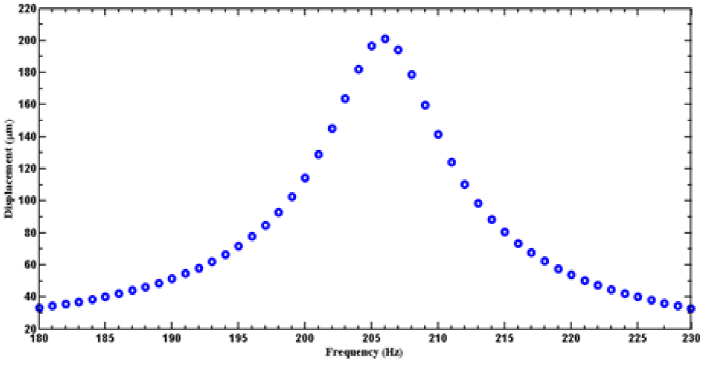
Fig. 6 Displacements along z-axis vs frequency of the PVEH device under a vibration acceleration along z-axis of 12 m/s2
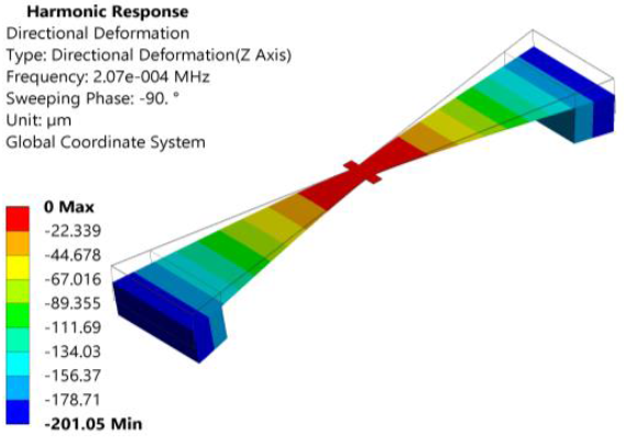
Fig. 7 Displacements distribution of PVEH device caused by a vibration acceleration along z-axis of 12 m/s2
The behavior of maximum principal stress of the PVEH device at resonance is shown in Fig. 8.
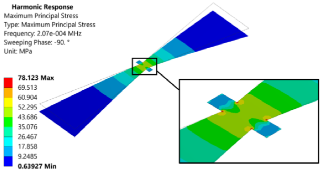
Fig. 8 Main maximum stresses in the piezoelectric material operating in resonance with load resistance of 10Kω
Its maximum value (78.12 MPa) is lower than the bending strength (162.25 MPa) of the PZT-5H material (Cheng et al., 2000), which is suitable to avoid structural damage during its performance. The maximum values of the principal stress are located around of the join (vertices) between the cantilevers and the support beams. Thus, the deformations and stresses of the PZT-5H film generate output voltages, as shown in Fig 9. The highest voltage (61.7 mV) is obtained at resonance considering an electrical resistive of 10 kΩ. Based on these values, the PVEH device generates a power maximum of 0.38 μW at resonance.
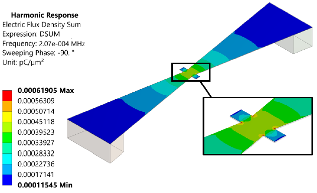
Figure 10 and 11 show the results of the electric field and electric flux density on the PVEH device.
The electric flux density maximum is placed on the surface of the highest principal stress value. The designed PVEH device can operate to the same frequency of an automobile engine, supplying an electrical power that can be used for automobiles sensors. This power can be increased using an electrical connection between several PVEH devices.
5 Conclusion
A MEMS-PVEH device based on the PiezoMUMPs fabrication process of MEMSCAP is designed. This device is composed by two silicon cantilevers of trapezoidal shape (2500 × 1064 × 9 μm), a PZT-5H film and two silicon proof masses. The proposed device takes advantage of the mechanical vibrations to generate voltage.
FEM models were developed to predict the electrical and mechanical behavior of the PVEH device. The FEM model results registered a resonant frequency of 207.8 Hz for an out-of-plane bending vibration mode.
For an acceleration along of z-axis of 12 m/s2 and an electrical resistive load of 10 kΩ, the PVEH device at resonance had a vertical displacement of 201 μm, a maximum principal stress of 78.12 MPa and generated voltage of 61.7 mV.
The designed device operates with a frequency close to that of automobile engines, which allows the increment of its generated power.
Future researches will include the optimization and fabrication of the PVEH device.


 nueva página del texto (beta)

