1. INTRODUCTION
Channel coding (digital) transforms the sequence of useful information into a discrete sequence encoded named codeword.
In 1948, Shannon (1948) showed that when the transmission rate of the system is less than the capacity of the transmission channel, the errors caused by the channel noise can be reduced to an arbitrarily low level by using a encoding and decoding of an appropriate. From that time, researchers have begun to explore different methods of construction of error-correcting codes. In this work, we focus on two families of error correcting codes: LDPC codes and turbo-codes.
LDPC (Low Density Parity Check) codes are a family of error correcting codes allowing approximate the theoretical limit predicted by Shannon correction it over 50 years ago. These codes were discovered by Gallager (1962) in the 60s, but were ignored until 1981 when Tanner (Tanner, 1981) devoted their new interpretation of a graphical perspective. A LPDC code is a code whose parity check matrix H of size (Μ χ Ν) is low density (Kou, Lin, & Fossorier, 2001). And the number of 1 in the matrix is small compared with the number of 0. The parity check matrix Η thus defines a block code where the number of information bits is Κ = Ν - M.
Turbo-codes are also a family of error correcting codes that allow approximate the theoretical limit predicted by Shannon correction. These codes, invented by Claude Berrou are obtained by concatenation of two or more low-complexity convolutional codes, separated by an interleaving function introducing diversity.
Recall that the decoding of the LDPC code and turbo-code uses an iterative process.
In what follows, we first recall the basic principles of the LDPC code and turbo-code. We perform a detailed description for the two families of codes. And we present the performance evaluated by simulation on a Gaussian channel. Also, the effect of iterative LDPC and turbo-code will be shown by simulation. We presented, a comparison will be made between the two codes. Finally, we will show the performance of the good channel coder use two pictures transmit in the Gaussian channel and Rayleigh channel.
2. THE LDPC CODES
2.1 INTRODUCTION TO LDPC CODES
The LDPC (Low Density Parity Check codes) were discovered by Gallager (1962) in the 60s, but has only proposed a general method to construct pseudo-random LDPC codes, the good LDPC codes are generated by computer and decoding is very complex due to the lack of structure.
These codes were ignored until 1981 when Tanner (1981) has given a new interpretation of a graphical perspective. After the invention of turbo codes, LDPC codes were rediscovered in the mid-90s by MacKay and Neal (1997), (Peterson, 1960) and Sipser and Spielman (1996). Construction and decoding of LDPC codes can be made in several ways. An LDPC code is characterized by its parity check matrix.
2.2 DEFINITION OF A LDPC CODE
LPDC code is a code whose parity check matrix H of size Μ χ N has a low density (Tanner, 1981). And the number of 1 in the matrix is small compared with the number of 0. The parity check matrix H thus defines a block code where the number of information bits is K = N - M.
Example: the following parity check matrix is considered a code of rate R = 1/2 and 4 producing redundancy bits:
The parity equations associated with this matrix and a codeword χ =[x0............x7] are:
X 0 +X 4 =0 (1)
X 1 +X 4 +X 5 =0 (2)
X 2 +X 5 +X 6 =0 (3)
X 3 +X 6 +X 7 =0 (4)
2.3 HYBRID LDPC CODES
Now we introduce a new class of LDPC codes, named hybrid LDPC codes (Sassatelli & Declercq, 2006). LDPC codes are a class of hybrid LDPC codes, involving regular and irregular LDPC codes, binary or non-binary.
2.4 BINARY HYBRID LDPC CODES
The binary LDPC codes (Sassatelli & Declercq, 2006) are described by the parity check equation involving some code word symbols. A binary LDPC code is a linear mapping a field GF(2) Κ to GF(2) N (Gallager, 1962).
2.5 GRAPHICAL REPRESENTATION OF BINARY HYBRID LDPC CODES
Multiplication of elements in the set GF (2) Κ can be represented as the following generator matrix (Gallager. 1962):
The equations associated with this generator matrix are:
X 0 +X 2 +X 3 +X 7 =0 (5)
X 0 +X 1 +X 3 +X 6 =0 (6)
X 2 +X 5 +X 6 +X 7 =0 (7)
X 1 +X 4 +X 5 +X 6 =0 (8)
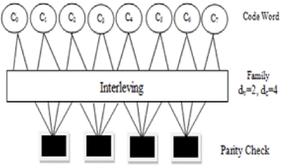
From this matrix (matrix H), Tanner (1981) came to the graph in Figure 1:
In Figure 2, we represent the Tanner graph (Tanner. 1981) of family hybrid LDPC codes parameters dv=2, dc=4.
2.6 GENERAL PARITY CHECK EQUATIONS
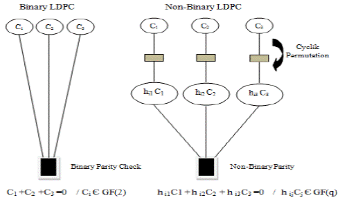
Either binary LDPC hybrid or non-binary codes. They are described with the parity check equation which corresponds to the i-tհ row of the matrix H, and is given as follows (Richardson, Shokrollahi, & Urbanke 2001):
The Tanner graphs (Tanner, 1981) corresponding to the binary LDPC hybrid or non-binary codes, related to equation (9) are shown in Figure 3.
2.7 DECODING OF LDPC CODES
Decoding of LDPC code (Paolini, 2007) is carried out according to an iterative algorithm known belief propagation algorithm. Each variable node sends the parity nodes to which it is associated with a message on the estimated value of the variable (a priori information). The entire message a priori received allows the parity constraint calculate and return the extrinsic information. The subsequent processing of variable nodes and parity is iteration. At each iteration, so there is a bilateral exchange of messages between the parity nodes and variable nodes on the edges of the bipartite graph of the LDPC code. At the receiver, the method of quantizing the received sequence X, determines the choice of the decoding algorithm.
3. THE TURBO CODES
3.1 INTRODUCTION TO TURBO CODES
The Turbo codes are error-correcting codes which can be close to the theoretical limit of correction. These codes, invented and presented by Claude Berrou at ENST Bretagne (Berrou, Glavieux, & Thitimajshima, 1993), are obtained by the parallel concatenation series (Benedetto & Montarsi, 1996) or hybrid of two or more error-correcting codes (Convolutional codes) of low complexity. Their decoding uses an iterative process (or turbo).
3.2 DEFINITION OF A TURBO-CODE
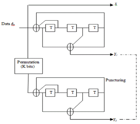
The Figure 4 shows the general principle of a turbo code, in its classic (Menezla, 2010) release.
The binary input message of length k is encoded in its natural order and a permuted by two coders called CI and C2 order. The two constituent encoders are identical, but it is not a necessity. In our example, the performance of natural coding without punching is 1/3, since for each source bit (dk) three bits (x, y1, y2) are sent to the channel. These bits are generated as follows:
The symbol χ is the data dk (we can already see the systematic);
The symbols y1 and y2 are respectively constructed parity bits by means of two identical encoders C1 and C2 . The only difference between y1 and y2 is that we swapped the order of the source bit (dk) for the second encoder C2 through an interleaver.
To get higher returns, punching redundancy symbols y! and y2 is made. And this gives the system its pragmatic approach (Menezla, Meliani, & Mahdjoub, 2012).
That we call it interleaving or permutation (Menezla. 2010), the technique of dispersing data over time has always been of great service to digital communications. It is used to advantage to reduce the effects of attenuation or long transmissions affected in blackouts and more generally in situations where disturbances can alter consecutive symbols.
In the case of turbo-codes, swapping effectively fights against the occurrence of burst errors, on at least one dimension of the composite code.
3.3 CONVOLUTIONAL CODES
The convolutional codes form an extremely flexible and efficient class error correction codes. These codes introduced in 1955 by Elias (Gaffour, 2006), can be considered as a special case of linear block codes. But from a broader point of view we can say that the additional structure equips convolute if linear code of favorable properties that facilitate both the coding and improve its performance.
The principle of these codes is not cut out the message finished blocks, but to consider it as a semi-infinite a0a1a2 ...sequence of symbols that passes through a succession of shift registers, the number is called memory code.
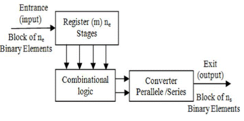
The convolutional codes operate such that each block of ns bits in the encoder output depends not only on the block consisting of only bits positioned at the input of the encoder, but also from m previous blocks . So this family of codes uses a serial memory effect m.
The quantity m = (m + 1): is called the constraint length of the encoder;
The ratio R = se / ns: is called the encoder performance.
The principle of the convolutional coding (Mostari, & Bekkar, 2000) is illustrated by the diagram of Figure 5.
A convolutional encoder to yield R and m constraint length is a linear time invariant system, of order m, at inputs and outputs ns.
Example of convolutional encoder
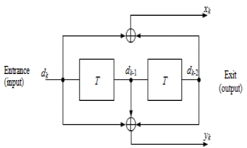
The Figure 6 is an example of a convolutional encoder of yield R =1/2 and constraint length μ = 3 (Bassou. 2000). Its input consists of blocks of binary symbols ne= 1 and the output of blocks of ns = 2 symbols.
This encoder produces two symbols for one symbol entering. So it converts a sequence of information symbols (.., dk-1, dk , dk+1, ..) to two sequences (.., хк-1, хк , хк + 1, ..) and (.., ук -1,Ук ,Ук + 1,…) of coded symbols. The input-output relationship is expressed in the form:
3.4 THE TECHNIQUE OF PUNCTURING
To obtain a transmission system having a high spectral efficiency on the one hand and to avoid the exponential growth of the complexity of the decoder increases with the coding rate for the convolutional codes of the other high rate, it is often useful to use codes which their performance is greater than 1/2.
The puncturing technique (Menezla, Méliani, & Mahdjoub, 2011) used to produce codes of various returns from a base code, the non-transmission of certain symbols from the encoder (see Figure 7).
For example, conventional punched codes are obtained from a code of rate 1/2 by deleting "no transmission" Periodic Xk and yk values, following a "mask" suitable punching indicating the positions of the symbols to be deleted.
This technique makes use of a simplified lattice, in which each node arrive only two branches as code for half performance. Decoding complexity is reduced, and the same decoder can then be used for a family of compatible punctured codes.
3.5 DECODING OF TURBO CODES
The turbo decoding is done on the principle of iterative decoding (Mostari, Méliani, & Bounoua, 2010). Or turbo based on the use of input and output decoders weighted or SISO (Soft Input Soft- Output) (Hoeher, 1997) exchange information reliability, they are called Expired extrinsic information through a feedback against, in order to Improve the correcting over the iterations.
The term TURBO (Toggle until Regenerations Bring Optimality) is the concept of looping similar to that used in turbo engines.
The circuit of a turbo decoder consists of the cascading modules Ρ corresponding to Ρ iterations of decoding the same Figure 8. Its structure is completely modular.
The input of the module P
éme
is composed of the received sequences
4. SIMULATION RESULT
4.1 LDPC CODES
The Figure 9 shows the simulation results evaluated by the Binary Error Rate (BER) on Gaussian channel for a hybrid LDPC code. We note in this figure the importance of the reaction against the reception level which results in the iterative effect.
4.2 TURBO CODES
The Figure 10 shows the simulation results evaluated by the Binary Error Rate (BER) on Gaussian channel for a turbo code. We note in this figure the importance of the reaction against the reception level which results in the iterative effect.

Fig. 10 Evaluation of the BER of a turbo-code with rate R = 1/2 on Gaussian channel and demonstration of iterative nature.
In the Figure 11, we show the behavior of various iterative error corrections in the fifth and sixth iterations. These codes will be the hybrid LDPC code; the turbo-code punched and turbo-code none punched.
5. DISCUSSION AND INTERPRETATION OF RESULTS
The Figure 9 and 10 show the effect of the iterative nature of the hybrid LDPC codes and turbo codes. These figures show that the BER decreases and as the number of iterations increases. For cons, the curves show that the hybrid LDPC code has better BER than the turbo code.
The Figure 11 shows the evaluation by simulation BER Perforated a turbo-code punctured, a turbo-code non-punctured, and hybrid LDPC code whit rate (R=l/2), in the fifth and the sixth iteration, depending on the signal to noise ratio Εb/Ν0 (dB) on a Gaussian channel.
If you choose a SNR in 1 dB, in the fifth iteration, the BER of the turbo-code not-punctured is 1.10-6, the BER of the turbo-code is punctured is 6.10-2 , through against the BER of hybrid LDPC code is 3,5.10-5. In this figure, we noted that the hybrid LDPC code remains attractive although the turbo-code not-punctured is better.
Other studies have done were they find that the LDPC gives a better BER for the Rayleigh channel for low SNR and the difference in dBs increases for higher values of SNR (Almaamory & Mohammed, 2012).
In Figures 12, 13, 14 and 15, we have presented the performance of a turbo code optimize and we have given:
A good puncturing;
Increase the number of modulation states;
Optimize the modulation constellation;
And finally a good adaptation to the channel.
The Figures 12, 13, 14 and 15 show that the BER as a function of SNR (dB) and are still very attractive while the receiver has a structure easy to work well as flows increase. This was done either by punching, that is to say by increasing the flow rate or increasing the number of modulation states, and any means that results are optimal.

Fig. 12 Performances on a Gaussian channel of a modulation MAQ-16 protected by turbo-code of return. 3/4(η = 3 bit/s/Hertz).

Fig. 13 Performances on a channel Rayleigh of a modulation MAQ-16 protected by turbo-code of return 3/4(η = 3 bit/s/Hcrtz).

Fig. 14 Performances on a Gaussian channel of a modulation MAQ-32 protected by turbo-code of return 4/5(η = 4 bit/s/Hertz).
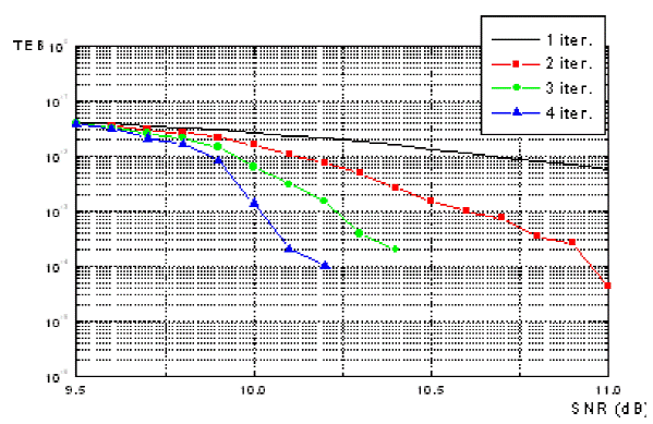
Fig. 15 Performances on a channel Rayleigh of a modulation MAQ-32 protected by turbo-code of return 4/5(η = 4 bit/s/Hcrtz).
Now, we see the effect of the latter on the transmission of two images (Mostari, 2008), for this we used two examples:
Figures 16 and 17 show the effect of the number of iterations on the image quality and we have found that the result obtained was much improved when the number of iterations increases. In a Gaussian channel, the image correction is performed for a number of lower iterations than that of a Rayleigh channel.

Fig. 16 The influence of the turbo-code on the transmission of the picture in the Gaussian channel (A)- received picture, (B) Picture decoded (1 iter.),(C) - Picture decoded (2iter.), (D) - Picture decoded (3 iter.), (E) - Picture decoded (4 iter.), (F) - Picture decoded (5 iter). (Mostari, 2008).

Fig. 17 The influence of the turbo-code on the transmission of the picture in the Rayleigh channel, (a)- received picture, (b) ֊ Picture decoded (1 iter.), (c) - Picture decoded (2iter.), (d) - Picture decoded (6 iter (Mostari, 2008).
6. CONCLUSION
In this work, we presented two major families of error correcting codes (channel encoders) which are LDPC (Low Density Parity Check) codes and turbo-codes. We used our simulation model to evaluate the performance of a Gaussian channel. The results show the effect of iterative LDPC and Turbo codes on the transmission and quality of information. We have shown the effect of the iterative nature of the two codes and we have shown that the hybrid LDPC code gives the best results relative to the turbo-codes punctured. Based on images obtained, we have noted that the image gradually was corrected as the number of iterations increases for both types of channels. On the Rayleigh channel, the image correction is done for a number of iterations higher compared to the Gaussian channel.


 nueva página del texto (beta)


