1. Introduction
Spin-coating is a fast, highly reproducible technique used for depositing thin films on a variety of substrates, such as Silicon, Quartz, and Sapphire. In spin-coating, a controlled centrifugal force is employed to uniformly distribute a material onto a substrate. This method is extremely desirable for applications where high-quality layers of thin films are required. This technique is widely used in the fabrication of devices in the micro and nanoscale, including sensors, polymer electronic devices, advanced drug delivery systems, semiconductor memories and magnetic storage devices, among many others (Madou, 2011).
An important element in spin-coaters is the vacuum chuck (VC), the component in charge of coupling the substrate to the motor. The vacuum chuck is usually attached to a motor with a hollow shaft. The perforation in the center of the motor’s hollow shaft allows coupling a vacuum system to the chuck while a perfect alignment with the motor shaft is achieved, reducing vibrations considerably (Bianchi et al., 2006). Other alternatives include the separation of the VC and the motor, while the torque is transmitted using a system of pulleys and bands (Gaur & Rana, 2014; Medina, Arámbula, Rizo, & Loera, 2009). Nonetheless, this mechanism of pulleys can induce a high degree of vibrations to the substrate. An example of commercial option of a VC with a non-perforated shaft is provided Rigaku®. It uses bearings with ferrofluids, which leads to very low vibrations but usually requires liquid cooling and has a limited the range of operation in terms of rotational speed (Rigaku, n.d.). Another way for transmitting the torque is by magnetic coupling, using a magnetic field rather than a physical mechanical connection. However, magnetic fields are never perfectly balanced and will always cause assemblies to shift to the lowest energy state. Consequently, all magnetic couplings require full mechanical support through radial and thrust bearings (Huang, Chen, Yau, & Sung, 2001; Wallace, Wohlgemuth, & Lamb, 1995; Yonnet, 1981).
As an alternative to VCs assemblies used in conventional spin coaters, in this work we present the development of a VC that couples to motors with a solid shaft without bearings. This VC was incorporated into a spin-coater fabricated in-house by our group at the Department of Basic Sciences at EAFIT University. Photoresist layers were spin-coated onto multiple substrates to test the working characteristics of the whole assembly. Initially, we describe the mechanical design as well as the working mechanism of the VC developed. Results on the working characteristics of the VC are presented as well. Those results include a discussion of the vibration and thermal characteristics of the whole spin-coater assembly as well as the characterization of the resulting spin-coated films in terms of their uniformity. Last, we present the conclusions obtained from this work.
2. Materials and methods
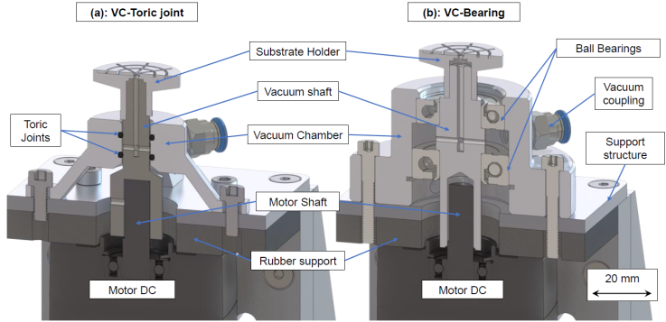
The VC described here is required to work with substrates of different sizes and geometries. In addition, the rotating head of the device should be separated from the rest of the system for cleaning and maintenance. According to these requirements, two VCs were designed. 3D cut views of the designs considered are presented in Figure 1.

Figure 1 3D cut view CAD design of the Vacuum-Chuck systems. (a) VC sealed with toric joints, (b) VC sealed with bearings.
As shown in Figure 1, both VCs consist of a shaft with perforated walls (vacuum shaft), a vacuum chamber, a substrate holder and a vacuum tube fitting. The vacuum chamber and motor shaft are mechanically coupled to the vacuum shaft. The function of the vacuum shaft is to hold the substrate in place using vacuum and to transfer the motor’s torque to the substrate holder. During operation, the air drawn by a vacuum pump passes through a filter to absorb any amount of photoresist or solvent poured onto the substrate. This filter protects the pump that attaches to the vacuum chamber.
In the design shown in Figure 1a, the vacuum shaft is sealed and aligned to the motor shaft by two toric joints. In the design shown in Figure 1b, the shaft is aligned and sealed by bearings instead of toric joints. The section of the shaft located between the toric joints, or bearings, has holes to allow air flow from the substrate holder to the vacuum chamber. The vacuum shaft was made of inox AISI 304. Aluminum 2024-T4 was used for all other components. To minimize frictional heating and vibrations, all pieces were fabricated using CNC machining.
To verify diameter variations of the vacuum shafts tested, these were mounted in between two live centers and the diameter was measured using a Mitutoyo Series 543 digital dial comparator gauge. Variations in the diameter of the vacuum shafts should be minimized to guarantee a good coupling with the motor’s shaft and the vacuum chamber. Variations in the vacuum shaft diameter can also lead to vibrations due to eccentricity and poor alignment to the other components.
The VC-motor assembly is completed by a Bodine DC brushless motor, series 22B model 3314. This motor is controlled by a Bodine Electric Company motor driver, model 3921. An analog control interface and voltage isolating module, Bodine Electric Company model 3984, is also used in this piece of equipment. The performance of the control system was validated for operating speeds ranging from 1000 to 8000 rpm. This measurement was done with a UNI-T digital tachometer model UT372, which has a resolution of 0.1 rpm.
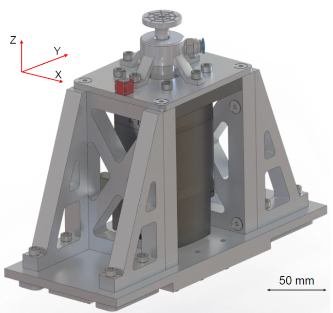
As shown in Figure 2, the motor was suspended from a metallic structure made of Aluminum 2024-T4. This structure was designed to reduce vibrations generated by the motor during spin-coating.

Figure 2 3D CAD illustration of the VC and motor support system, the red cube is the triaxial CCLD accelerometer.
To check the stability of the whole assembly, vibrations of the plate supporting the motor and vacuum elements were measured at different rotational speeds. These tests were made using a triaxial CCLD accelerometer type 4524. It allowed to measure acceleration of the plate in the x, y and z axes. The measured acceleration data was processed in MATLAB using the following procedure. First, measured frequencies below 15 Hz were filtered out to remove values that do not correspond to vibrational modes of the system. The filtered data was then integrated twice in order to find the spatial displacements. Finally, the RMS values of the acceleration and the displacements were calculated.
Variations in the temperature of the substrate holder surface were measured with a FLUKE-62 Compact Infrared Thermometer. These measurements were done for periods of four minutes for each spin speed in the range of 1000 to 8000 rpm. The system was allowed to cool down in between tests.
Photoresist (PR) films were also deposited at different rotational speeds. The thickness and uniformity of the films spin-coated across 50 mm silicon substrates were measured using a Filmetrics F3 spectral reflectometer. Results of PR thickness obtained at 1000, 2000, 3000 and 4000 rpm were compared to data provided by the PR manufacturer and results are summarized in the following section.
3. Results and discusion
Table 1 presents the mean
(
Table 1 Spin speed precision and accuracy for the DC motor and control system.
| rpm | χ(rpm) | σ(rpm) |
| 1000 | 1000.1 | 2.4 |
| 2000 | 2000.2 | 2.2 |
| 3000 | 3000.5 | 3.1 |
| 4000 | 4000.4 | 1.7 |
| 5000 | 5000.2 | 1.6 |
| 6000 | 6000.1 | 1.7 |
| 7000 | 6999.7 | 2.0 |
| 8000 | 8000.8 | 4.8 |
As seen, the mean value of the rotational speed deviates less than 1 rpm from the setpoint value for the entire range of operation. Furthermore, the standard deviation was found to be between 1.7 and 4.8 rpm for the whole range of operation. These results indicate accurate and stable operation of the motor driver, which is paramount for adequate control of the photoresist thickness.
After confirming the correct operation of the DC motor driver, it is important to validate that the VC design yields low vibrations. To achieve a low-vibration behavior, a perfect alignment between the vacuum shaft, the motor shaft and the vacuum chamber is required, see Figure 1 for additional details on these components. Table 2 summarizes the variations in diameter in different regions of the vacuum shafts fabricated for the VC designs analyzed in this paper.
Table 1 Diameter variation of the vacuum shafts.
| Shaft | Region | Δθ(µm) | σ(µm) |
| VC-Toric joint | Motor coupling | 8 | 1 |
| Toric joint contact | 38 | 11 | |
| Substrate holder coupling | 35 | 11 | |
| VC-Bearings | Motor coupling | 2 | 3 |
| Bearing contact 1 | 138 | 6 | |
| Bearing contact 2 | 45 | 9 | |
| Substrate holder coupling | 55 | 34 |
A comparison of the diameter variations for the different regions of the vacuum shafts indicates that the design using toric joints has a better match to the design parameters. It is within an IT9 range of the ISO system of limits and fits our fundamental tolerances. On the other hand, the design using bearings falls in an IT11 range. This is due to the manufacturing process of both shafts. The manufacturing of the shaft in the design using bearings requires dismounting the piece from the CNC machine multiple times, while the design using toric joints can be fabricated in a single operation.
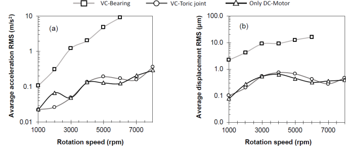
Poor mechanical alignment between these components would amplify vibrations generated by the motor. This is, vibrations greater than a few microns would lead to non-uniformities in the thickness of the spin-coated photoresists. Figure 3 shows the measured acceleration and displacement of the two VC designs tested.

Figure 3 Vibrations measured as a function of the rotational speed for the different VC designs. (a) Average acceleration RMS, (b) average displacement RMS.
As seen in Figure 3, the VC design using bearings has acceleration RMS and displacement RMS values, an order of magnitude larger than the VC design using toric joints. It can also be seen that the vibrations measured for the DC motor alone are in the same range as the vibrations measured for the VC with toric joints. These variations are in the range of 0.02 m · s-2 at 1000 rpm and 0.35 m · s-2 at 8000 rpm. This result indicates that a perfect coupling and alignment between the motor shaft and the VC with toric joints is achieved.
The shape of the curve shown in Figure 3 a is due, in part, to the natural frequencies of vibration of the DC motor, as well as by the natural frequencies of vibration of the motor coupled to the different VC designs. In the case of the motor only, these frequencies were found to be at 33.3 Hz and 66.6 Hz, which correspond to 2000 and 4000 rpm, respectively. When the DC motor is coupled to the different VCs, the mass of the system changes, therefore displacing the natural frequencies of the assembly.
For the VC with toric joints, these natural frequencies lead to a maximum in the average acceleration RMS around 5000 rpm, which corresponds to 83.3 Hz. In the case of the VC with bearings, this system is heavier and more rigid than the VC with toric joints. Consequently, the former has a greater moment of inertia when compared to the latter. As a result, the VC with bearings has vibrations of greater magnitude, as summarized in Figure 3. In addition, the soft material of the toric joints in the VC-toric joint design dampens part of the radial components of acceleration, reducing the vibrations and minimizing the misalignment with the motor shaft. This damping effect for the VC-toric joint design is seen in the acceleration (Figure 3 a ) as well as in the displacement (Figure 3 b ) curves. A maximum displacement for the VC-toric joint of 0.7 µm was found around 4000 rpm, which agrees with the maximum displacement measured for the motor only system. In general, the measured displacements for the motor only and the VC-toric joint system vary in less than 1 µm. Meanwhile, displacements for the VC with bearings are between 2.2 and 16 µm larger than those of the motor only system. Therefore, it is possible to conclude that the VC-Toric joint design is the best design for our spin-coater. From here, the VC design with bearings was discarded and the analysis refers to the VC design using toric joints.
Figure 4 shows the variation in temperature of the substrate holder surface as a function of time of operation and rotational speed. The temperature variation is presented as a ΔT, calculated with respect to an ambient temperature of 25 °C. These measurements provide information about the friction in the assembly, which can occur mostly between the vacuum shaft and the toric joints. The surface roughness was measured using a Mitutoyo Surftest SJ-201P instrument, in this section of the shaft, the value was 1.8 ± 0.3 µm. It falls in the N7 ISO grade number, which is adequate for dynamic sealing.
Figure 3 Temperature increase in the substrate holder surface as function of spin speed.
As presented in the inset of Figure 4, an increase in the substrate holder temperature below 1 °C is measured for all rotational speeds tested for operating times up to 60 seconds. Therefore, unwanted heating of the substrate holder is not expected to have any significant effect on the photoresist deposited with the spin-coater described here. This is particularly true if we consider that spin-coating processes used for conventional photoresists are usually carried out at rotational speeds in the range of 200 and 5000 rpm with spinning times in the range of 10 to 60 seconds. Higher variations in the substrate holder temperatures are observed for spin-coating times above 60 seconds and rotational speeds greater than 5000 rpm. The increase in temperature can have a negative effect on the spin-coated resist while decreasing the lifetime of the VC. This increase in temperature is due to heat transfer between the region where the toric joints are in contact with the vacuum shaft, the motor and substrate holder.
Consequently, our spin-coater can be used in continuous mode for rotational speeds up to 4000 rpm. Processes that require higher rotational speeds should include pauses every 60 seconds of operation to allow for cooling of the assembly.
As part of the qualification of the spin-coater, the level of vacuum pulled on the substrates was also measured. The vacuum pressure achieved by the system was about 0.05 Bar and it remained at this value while the vacuum shaft was spinning. This vacuum level was held during 4 minutes after the vacuum pump was turned off. This result guarantees that the substrate will be securely held in place throughout the spin-coating process.
Spin-coating tests with a duration of 30 seconds were carried out at 1000, 2000, 3000 and 4000 rpm. Thickness measurements were done at different radial positions in the 50 mm wafers. Results are summarized in Figure 5 and Figure 6.
Figure 5 shows the radial dependence of thickness for different spin-coating speeds. For all rotational speeds tested, the PR was found to be thicker in middle of wafers. This thickness was found to decrease toward the edges of the substrate. In general, the differences in thickness between the center and the edges of the wafer are below 50 nm. This trend in PR thickness variation across circular substrates has been reported before for other spin-coating systems (Flack, Soong, Bell, & Hess, 1984; Jenekhe & Schuldt, 1985; Sukanek, 1991; Washo, 1977). This behavior is not expected to have a significant effect on the features that can be obtained by performing photolithography with the spin-coated resists.
Additionally, Figure 6 shows the PR thickness as a function of spin-coating speeds. When experimental data is compared to the curve reported by the manufacturer, a good match is observed for spin-coatings performed in the 3000 - 4000 rpm range. A greater deviation is observed at lower speeds (1000 - 2000 rpm). As it was discussed before, the control and vibrations of the spin-coating apparatus are well within specs. Therefore, these deviations from the manufacturer data are believe to be due to changes suffered by the PR over time, including evaporation of solvents, degradation of the active components as well as changes in the solid content of the solution.
Nonetheless, the manufacturer of ma-P 1205 photoresist recommends to perform the spin-coating at rotational speeds of 3000 and 4000 rpm. For these conditions, the measured PR thicknesses are in good agreement with those reported by the manufacturer. For instance, at 3000 rpm the measured PR thickness is 0.42 ± 0.02 μm and while the value reported by the manufacturer is 0.44 μm (Micro Resist Technology, n.d.).
4. Conclusion
In this paper we presented the construction and operation of a spin-coater featuring a low-vibration VC. Two VC designs were considered, one with bearings and another one with toric joins. The VC with toric joints was found to have a better coupling to the vacuum system as well as the vacuum and motor shafts. This vacuum shaft can be coupled to a variety of motor shafts. The system described here can be operated at a wide-range of rotational speeds, going from 100 to 8000 rpm. It can be operated in continuous mode at rotational speeds up to 3000 rpm. For rotational speeds between 3000 to 8000 rpm, the system is recommended to be operated in batch mode, allowing the whole assembly to cool down after every 60 seconds of operation.


 nueva página del texto (beta)


