1. Introduction
The sun is a vital source of energy, which may be exploited in several fields such as drying of agricultural products, production of hot water, etc. All these applications can only be realized with devices that allow us to capture solar radiation that arrives on earth, such as solar collectors.
Some works have been achieved on the subject; among others, Ramani et al. (2010) investigated theoretically and by experiments the performance of a collector with double air pass with and without porous material. Deng et al. (2015) interested in a solar with a single air pass. Moss et al. (2018) used a solar collector with a flat plate absorber in order to reduce the heat losses and enhance efficiency. Abuşka and Şevik (2017) examined by experiments the impact of environment, economic of solar air collectors. By numerical simulations and experiments, Saedodin et al. (2017) showed the thermal and dynamical performance of a solar collector with a flat plate absorber in the case of the presence of a porous metal material. Chen et al. (2015) compared the performance of solar collectors experimentally in various cases. Kalaiarasi et al. (2016) showed an energy study with an exergy analysis of a solar collector with a flat plate absorber. Mohammadi and Sabzpooshani (2013) mounted obstacles over the absorber to enhance the performance of a solar heater with a single pass. Mohammadi and Sabzpooshani (2014) explored numerically the performance of a solar air heater with baffles under the external recycle effect. Bayrak et al. (2013) analyzed the energy efficiency of porous material obstacles inside solar heaters at air. Peng et al. (2010) used pin-fin on the absorber to enhance the efficiency of solar air collectors. Hu et al. (2013) inserted baffles on the absorber to improve the heat transfer a solar collector at airflow. Youcef-Ali and Desmons (2006) studied, through experimental and numerical analysis, the efficiency of a collector of solar energy with fins on the flat plate absorber. Kabeel et al. (2018) used an experimental approach to study the characteristics of a solar collector with fins in its single-pass. They examined the effect of fins height inserted in their longitudinal section on the overall performance. Deng et al. (2016) presented a simple model of characterization of thermohydraulic performances. This new model is based on the concept of the piston flow in the presence of solar collectors with flat plate absorbers. Baccoli et al. (2015) studied theoretically the energetic performance of a solar collector using an analytical technique. Priyam and Chand (2018) interested in a solar air heater with a single pass and a flat absorber. They examined the amplitude impact of the wavy section and wavelength of fins on the overall efficiency. Priyam and Chand (2016) studied the effect of flow rate on the thermal efficiency of a solar air collector with an absorber mounted with wavy fins. They also presented the effect of the number of these obstacles on the thermal behavior. Some other crucial numerical analyses on the thermohydraulic characteristics of solar channels with obstacles were reported in the literature (Menni, Ghazvini, Ameur et al., 2020; Menni, Ghazvini, Ameur, Kim et al., 2020; Menni et al., 2022; Merabti et al., 2019).
In this paper, the performance of a solar water collector equipped with seven parallel tubes over an aluminum absorber and a simple white glass cover is investigated. The study is achieved for three flow rate values (0.001, 0.0003, 0.0003 kg/s), and irradiation of 1000 W/m2.
2. Solar collector under study
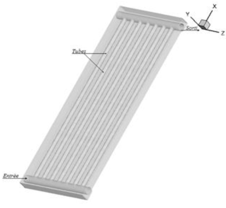
The geometry proposed in this work is presented in Figure 1. It is a water collector with a height (H), width (W) and length (L), equipped with seven aluminum tubes placed in parallel over an aluminum absorber and a simple white glass cover, whose geometric and physical parameters are given in Tables 1 and 2.
Table 1 Geometric parameters of the collector.
| Parameter | Value |
|---|---|
| H (cm) | 4.5 |
| L (cm) | 94 |
| W (cm) | 36 |
| l(cm) | 87 |
| w (cm) | 4.5 |
| r (cm) | 1 |
| R (cm) | 1.75 |
| n | 7 |
| Ufe (kg/s) | 0.001, 0.0003 and 0.0001 |
| Tfe (K) | 303.2 |
3. CFD-based 3D simulation
The flow governing equations are the continuity, the Navier-Stokes, and the energy equations. These equations are used to simulate the steady incompressible fluid flow and the heat transfer within the computational domain. They are given as follows:
Continuity:
Momentum:
Energy:
where: u, v and w are the components of the velocity field along x, y, z in the Cartesian coordinates, P the pressure, ρ and μ the density and the viscosity, Cp Specific heat, T temperature, and λ thermal conductivity.
These equations are solved using finite volume method (Patankar, 1980), QUICK scheme (Leonard & Mokhtari, 1990), and SIMPLE discretization algorithm (Patankar, 1980). These techniques have been used previously by some researchers for the treatment of various industrial problems and satisfactory results were obtained (Ameur 2016a; 2016b; 2018; 2019a; 2019b; 2020a; 2020b).
The boundary conditions in the fluid and solid are given as follows:
Inlet
For water
For absorber and insulator
-Outlet
For water
For absorber and insulator
-Walls
4. Results and discussion
In order to improve the productivity of the solar device, the coupling of these systems with a solar collector can be used. In this work, a special attention is paid to the flow of water and the heat transfer inside the tubes of the collector (Figure 2).

Figure 2 Geometry of a solar collector equipped with seven parallel tubes over an aluminum absorber and a simple white glass cover.
Figure 3 reports a three-dimensional visualization of water flow through the solar water collector, which is equipped with seven tubes that are placed in a parallel arrangement.
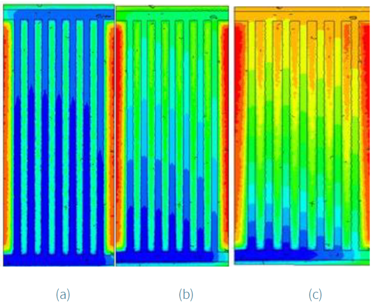
Figure 4 illustrates the variation of temperature profiles (XZ) of the water inside the tubes and the absorbent wall, at the median cross-section (Y = 0) and for different flow rates.

Figure 4 Contour plots of temperature fields (in XZ) of water for different mass flow rates: (a) U fe = 0.001 kg/s, (b) U fe = 0.0003 kg/s, and (c) U fe = 0.0001 kg/s.
Figure 4b shows a lower mass flow of U fe = 0.0003 kg/s. The result revealed that the water begins to heat properly, where its temperature reaches the value of T fs = 316 K in the outlet section.
Figure 4c shows a low flow rate of U fe = 0.0001 kg/s. It is clearly observed that the water temperature increases gradually along the tubes, where it reaches the value of T fs = 324 K, because the stay of the water inside the tubes will be much slower. In this situation, the fluid receives more energy that is transferred through the absorbent wall. This case is, therefore, the most favorable for an efficient collector, and the value of U fe = 0.0001 kg/s provides the optimal mass flow rate through the tubes.
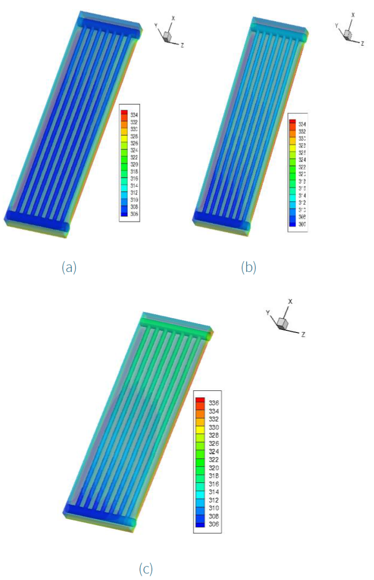
Figure 5 shows the heat exchange between the absorbent plate and the tubes that are placed in parallel. It is noted that, for low mass flow and with irradiation of 1000 W/m2, the absorbing plate releases a temperature of T abs = 334 K, which is used to heat the water circulating inside the tubes, where the temperature reaches 324 K (Figure 5c).

Figure 5 3D temperature profiles of the water and absorber for different mass flow rates: (a) U fe = 0.001 kg/s, (b) U fe = 0.0003 kg/s, and (c) U fe = 0.0001 kg/s.
The temperature distribution in the seven tubes is not symmetric due to the different velocities, which causes different pressures in each tube. The fluid quantity is not equally divided in the tubes divided and it is depending on the distance from the main entrance.
Figure 6 shows the variation of temperature in the last tube. We note that the temperature of water increases gradually along the tube, because it receives heat released across the absorbent wall during its stay, where the temperature reaches 324 K at the outlet.
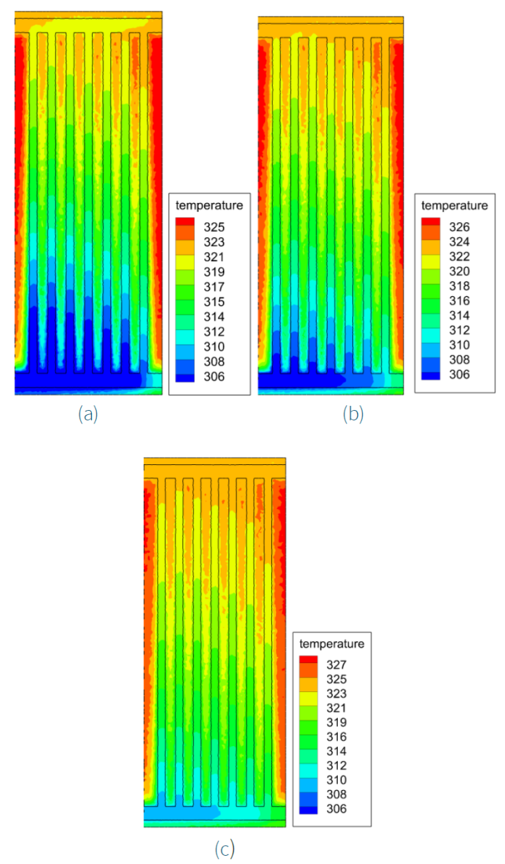
The temperature of the water inlet (T fe) is mentioned in Table 1, where T fe = 303.2 K. In addition, the contour plots of temperature fields of different inlet water temperatures T = 298 K, 303.2K, and 308 K for U fe = 0.0001 kg/s are illustrated in Figure 7. There is an increase in outlet temperature with increasing inlet temperature for the same mass flow rate.

Figure 7 Contour plots of temperature fields of different in let water temperature (a) T = 298 K, (b) T = 303.2 K, (c) T = 308 K for U fe = 0.0001 kg/s.
The efficiency is calculated by the following equations:
Using this equation, the obtained results of the efficiency are: η0.001 = 0.061, η0.0001 = 0.016, η0.0003 = 0.077.
5. Conclusions
Three-dimensional numerical modeling of the thermohydraulic behavior of a solar water collector was performed. This study is based on the comparison between different mass flow rates in order to optimize the stay of the water circulating inside the tubes and to have a larger temperature spread at the outlet of the collector. Our numerical model was based on the general equations of mass conservation (continuity), momentum, and energy.
The obtained results highlight the influence of the mass flow rate on the temperature of the water because the heat transfer between the absorbent wall and the tubes will be more and more critical when the water circulates slowly. The lower mass flow rate yields a longer residence time and increases the outlet temperature.


 nueva página del texto (beta)


