This paper is dedicated to Dr. Jorge Ibañez Cornejo as part of the JMCS special issue: "Tribute to emeritus SNI Researchers in the area of electrochemistry."
Introduction
We present our approach to obtain a broad electrochemical window out of acetonitrile (CH3CN), one of the most widely used solvents in electrochemistry for studies of organic compounds. This solvent has several advantages that make it suitable for electron transfer studies and electrosynthesis in aprotic media. [1-3] Acetonitrile dissolves salts required to prepare the supporting electrolyte, such as tetraalkylammonium perchlorates, hexafluorophosphates, and tetrafluoroborates. It is also widely used in cathodic and anodic regions because of its relatively large electrochemical window. The electrochemical window is the region in which pure acetonitrile does not get electrolyzed, and thus, there are no faradaic currents due to oxidation or reduction of CH3CN. Acetonitrile is usually a less effective solvent to dissolve nonpolar samples, but CH3CN /benzene mixtures have been used to study aromatic molecules, [4] including some of us. [5] These benzene/acetonitrile mixtures rely on clean acetonitrile to provide a sizeable electrochemical window, just like pure CH3CN. This paper deals with the issue of the electrochemical potential window as it relates to the purity of the supporting electrolyte, i.e., the solvent and the dissolved electrolyte salt. In practice, the solvent and supporting electrolyte salt purity limit the electrolyte window. Our group found that these impurities vary among different commercial sources and even across batches of the same source. Therefore, we often must troubleshoot the purification of solvent and salt (supporting electrolyte). Here we present an approach to verify and improve the purity and, therefore, the potential window of an acetonitrile/tetrabutylammonium perchlorate salt (CH3CN/TBAP) to yield a sizeable electrochemical window suitable for cathodic and many anodic processes. We discuss the purification of CH3CN and TBAP and how the experimentalist can learn from the electrochemistry of the system to guide the purification toward the preferred potential window. We base our methods on a review of the literature on the purification of CH3CN and provide our currently preferred procedure to provide a solvent with acceptable impurities level for applications in the cathodic and anodic regions. Interestingly, although there are many papers about the purification of the solvent, cyclic voltammograms (CVs) are seldom shown for the final solvent and supporting electrolyte system or at different purification stages. Here, we use CVs to illustrate the purification process and the CV window as a guide for solvent purity.
The optimized procedure yields a solvent with small background currents, essential for electrochemical measurements from a signal-to-noise (S/N) perspective; we discuss how to estimate a maximum allowable background current for a CV. Besides the S/N enhancement, smaller background currents that result from higher-purity solvents minimize the chances of chemical complications. For example, in studying the reduction of an aromatic compound, A, reduction can produce a radical anion: [6]
Radical anions, A((, are usually highly reactive, and purifying the solvent minimizes the risk of impurities reacting with the reduced A(( species and increases the probability that reaction (1) will be chemically reversible.
Several methods to purify acetonitrile exist, along with conflicting accounts for achieving the required purity for electrochemical measurements. Here, we include the most relevant to our purification method. The impurities include acrylonitrile, acetic acid, aldehydes, amines, and water. [2,3,7,8] One of the procedures involves distillation from P2O5, but because of solvent polymerization, this procedure does not have high yields.
[8] Some electrochemical manuals and reviews recommend distilling from CaH2, [2,3] although others state that CaH2 is ineffective in drying CH3CN. [8] Another popular procedure is to let CH3CN on top of molecular sieves (3A) for 12 h or more. [9] Some claim that this method makes the water concentration less than 1 ppm or <0.05 mM, ref [10] while others claim that 3A sieves are less effective at removing water and can only decrease the H2O concentration down to 30 to 50 ppm (ca. 2.7 mM), [11] and approximately 1 mM. [8] Nevertheless, these 3A sieves are reported to yield a sufficiently dry solvent for many applications. Activated alumina is another drying agent initially proposed to purify acetonitrile in a pack flow-through column [7] that is also used as a static agent. When used on their own for static drying, we found that these desiccants do not provide a suitable solvent for many of our electrochemical experiments. Therefore, we combine these methods inspired by a purification apparatus that runs the solvent through a series of columns packed with different desiccants [12,13] to get a solvent with a relatively high electrochemical window. We present our optimized procedure along with the more significant optimization experiments.
Experimental
Optimized procedure
We used CH3CN HPLC grade (Fisher, 300 mL) and treated the solvent with molecular sieves 3A (10% volume of CH3CN) for 48 hours in a drierite desiccator. We transferred the solvent to a distillation flask and added CaH2 until the hissing stopped, and we added approximately 1 g of excess CaH2 to distill the solvent. The distillation was carried out at 80 (C. We discarded the first 5 mL and collected the distillate on a round bottom flask containing recently activated alumina (MP Alumina N-super I, EcoChrom, 13.65 g), collecting 250 mL. All the distillation process occurs in a Schlenk line set up, and we transferred the solvent to an Ar glove box. We used the alumina within 24 h of activation in air or after storing it in an Ar glove box (O2 and H2O concentration < 1 ppm). We prepare a solution (2 mL) of 0.1 M TBAP inside the Ar box. The TBAP salt was recrystallized from ethyl acetate and 95 % ethanol. The electrolyte solution was treated with alumina (100 mg / 2 mL) to yield the electrolyte with the largest electrochemical window. We activated the Al2O3 by heating it to 400 °C for 4 h in a benchtop muffle furnace (Thermolyne); after cooling it to 150 (C, we quickly transferred the alumina to the Ar glove box for storage. We activated the 3A molecular sieves by baking them in air at 250 (C for 12 h at 52 torr, and while they were still hot, they were transferred to a drierite desiccator.
Electrochemical measurements
Electrochemical measurements were performed using a closed, one-compartment cell in a three-electrode configuration. The working electrode was a Pt disk electrode sealed in glass and made in-house. The diameter of the platinum disk was 2.3 mm; an Ag wire was used as a quasireference electrode (QRE), and a Pt wire was used as the counter electrode. The potentiostat was a CH Instruments workstation (Austin, TX). All potentials were measured against a quasi-reference of silver wire and ultimately converted to the standard calomel electrode (SCE), using Fc (E = 0.31 V vs. SCE) [6] as is customary for nonaqueous studies. Unless otherwise noted, the supporting electrolyte was 0.1 M TBAP. For experiments using CH3CN without distillation, the solutions were prepared on the bench, so the solvents were exposed to air unless otherwise noted. We plot cathodic currents as negative.
Carbon deposits on Pt
The Pt electrode was modified by adapting a procedure reported before. [14] Briefly, a parafilm candle was used as a carbon source. After lighting the wick, the smoke rising from its flame passed through a pinhole and deposited on the electrode. The loss of the metallic shine on the Pt surface confirmed the soot deposit on a Pt electrode.
Reagents
Acetonitrile was HPLC grade (Fisher Chemicals), while the tetra-n-butyl ammonium perchlorate was purchased as "electrochemical grade" (Alfa Aesar). For the purification of TBAP, ethyl acetate HPLC grade (Sigma-Aldrich), 95 % ethanol (Koptec), and pentane (Fisher) were used. We recrystallized the tetra-n-butyl ammonium perchlorate twice. First, TBAP was dissolved in ethyl acetate (2 g in 40 mL) and placed on a heating plate at 90 (C to remove ca. 10 % of the solvent. This step was done in a hood and required additional safety precautions due to the flammability of the solvents. Second, the TBAP solution was placed in an ice bath and filtered with a Buchner funnel with a fritted disc. The recovered TBAP was dissolved in 40 mL ethanol-water 95 % and recrystallized using the procedure for ethyl acetate. Finally, the TBAP recovered was washed once with 20 mL of pentane (Fisher, used as received) and heated at 110 °C under a vacuum overnight (52 Torr); we recovered 70 % of the initial TBAP. Purification of CH3CN was conducted by distillation in an Ar atmosphere, using calcium hydride (Alfa Aesar, used received). Ferrocene (Fc) and LiClO4 (Alfa Aesar) were used without further purification.
Theoretical background
We present a method to estimate the background currents required for a CV experiment. Taking the peak current for a thermodynamically reversible CV according to Eq. (2): [6]
Where i p is the peak current, n is the number of electrons, A the electrode area (cm2), D is the diffusion coefficient (cm2/s), C* is the bulk concentration (mol/ cm3), and ( is the scan rate (V/s). Rearranging and taking D = 1 ( 10-5 cm2/s, ( = 0.1 V/s, as usual values, we get:
It is helpful to use the current density, j:
where i is the current, and A is the area as before. For a typical D = 1 ( 10-5 cm2/s, and C* = 1 mM, the current density at the CV peak is expected to be in the order of 269 (A/ cm2. To estimate permissible background current, we use the condition that the analytical signal should be ten times the noise. In this case, the noise would be the faradaic background current, so we get the relationship:
where i bkd is the permissible background current, this makes the maximum allowable current density for the solvent approximately 30 (A/ cm2, which is consistent with the usual definition of the electrochemical solvent window as the limits at which the background current from electrolyzing the solvent is of a "few microamps/cm2". [6]
Besides contributions from electrolyzing the solvent, the Faradaic background current can be due to an impurity in the solvent that carries onto the supporting electrolyte. Suppose the current is due to an electroactive impurity in the electrochemical window of interest. In that case, we can estimate a higher limit for the concentration of impurities, taking j p = j bkd = 30 (A/ cm2 and solving from Eq. (2), which gives us the typical maximum permissible concentration for the impurities to be in the order of 0.1 mM. Again, these numbers are calculated assuming typical D values, which are reasonable assumptions for many small molecules in nonaqueous solvents, e.g., for anthracene in CH3CN, D = 2.55 ( 10-5 cm2/s. [15] In summary, for many experiments and concentrations of 1 mM, we can use a solvent where the background current density is < 30 (A/cm2, which likely results from making the concentration of impurities in the order of 0.1 mM or less. Here, we present a method to provide a solvent with a window of ca. 4.5 V, with current densities < 30 (A/cm2.
Results and discussion
Fig. 1 shows the CVs for 0.1 M TBAB without purification in HPLC grade acetonitrile as received and (---, black) after treatment with activated alumina for 10 min (---, red). Interestingly, the background currents in the CH3CN without purification are relatively high and above 100 (A/cm2. Another interesting point is that treatment with freshly activated alumina decreased some background currents in the 1.5 to -1 V vs. SCE region but did not decrease the background current in many other CV areas. The background current remains relatively large at a potentials negative of -1 V. Also, scanning in this cathodic region results in surface modification due to the reduction of impurities, as indicated by the current trace crossing-over (see Fig. 1 inset). The peak around -1 V is associated with water and O2. Fig. 2 shows the effect of purging the electrolyte with Ar, comparing the CV for the solvent as received (black trace) with the CV after purging (---, red). The purge time was 20 minutes, with Ar previously passed through CH3CN to avoid drying the electrolyte and changing its concentration. Also, adding water to CH3CN made the peak at ca. -1 V vs. SCE increase (not shown). After purging, (---, red), the peak at -1 V vs. SCE is not as evident, and the current decreased to a plateau above the double layer charging. Therefore, the peak at ca. -1 V is probably associated with O2 and H2O reduction, contributing to the background current. Consequently, we propose that the peak at -1 V vs. SCE is primarily due to O2 reduction coupled with H+ from residual water in CH3CN.
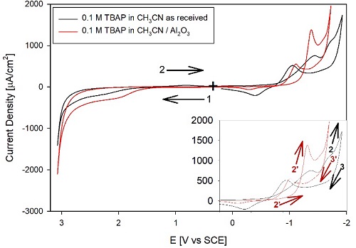
Fig. 1 CVs of 0.1 M TBAP in (-----, black) acetonitrile HPLC grade as received and (---, red) after treatment with activated alumina. The TBAP was used as received. The graph shows four segments, Ei = 0 V, ( = 0.1 V/s. The inset shows the cathodic region with the same x-scale. (+) marks the starting point of the CVs, while the (1 () arrows indicate the initial direction of the potential scan.
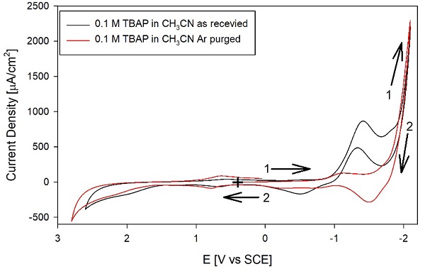
Fig. 2 CVs of 0.1 M TBAP in (-----, black) acetonitrile HPLC grade as received and (---, red) after purging with Ar. All other conditions as in Fig. 1.
We also attempted to purify the solvent with 3A molecular sieves. Fig. 4 shows the voltammograms for a solvent treated for over one week with molecular sieves. Like the Al2O3 treatment, the molecular sieves are effective in some regions of the CV, but at the anodic and cathodic ends, the background currents remain large. The red trace in the graph shows the addition of 1 mM Fc, which is consistent with the expected reversible behavior. Note that on many of the CVs' cathodic regions, the outgoing and the return scans cross over, indicating that the electrode is being modified during the potential excursions to the cathodic extremes. So, the Fc is necessary to calibrate the potential of the quasireference Ag wire and is also a test to rule out a passivated working electrode. In this case, the Fc CV is consistent with a Pt surface that has not been passivated. Given the results obtained with Al2O3 and 3A molecular sieves, we distilled CH3CN from CaH2 under Ar to remove residual water and other impurities.
Fig. 4 shows the results obtained with an electrolyte prepared with CH3CN, treated with 3A molecular sieves, and distilled from CaH2 using the TBAP as received. Although the background currents have decreased after distillation on most of the CV, consistent with removing most impurities, as discussed below. However, reducing most background currents made an oxidation peak evident around +2.5 V vs. NHE. The figure compares the CV for 0.1 M TBAP and 0.05 M TBAP without purification. Note that diluting the supporting electrolyte by 50 % decreases the oxidation peak current of approximately the same percentage. Therefore, we assigned this peak to an impurity in the TBAP and purified it by recrystallization, ultimately from two solvents (ethyl acetate ether and 95 % ethanol-water). These CVs illustrate a common problem with preparing nonaqueous electrolytes: an electroactive impurity can be in the solvent or the salt; in this case, by diluting the electrolyte, we could assign the electroactive impurity to the TBAP.
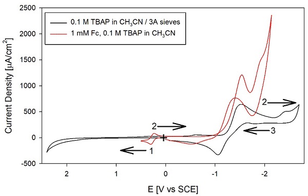
Fig. 3 CVs of 0.1 M TBAP in CH3CN, after treating the solvent with 3A molecular sieves. ( , black) supporting electrolyte, and (---, red) adding 1 mM Fc. All other conditions as in Fig. 1.
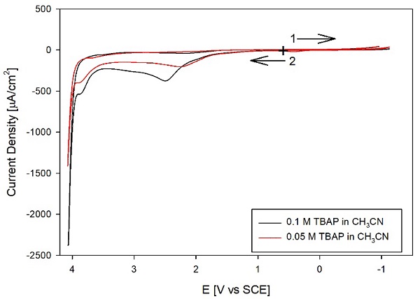
Fig. 4 CVs of TBAP in distilled acetonitrile with different concentrations of supporting electrolyte: 0.1 M TBAP (-----, black) and 0.05 M TBAP (---, red). The TBAP was used as received-all other conditions as in Fig. 1.
In our optimized procedure, we use CH3CN that has been pre-treated with 3A molecular sieves, distilled from CaH2, and collected and stored over Al2O3. The TBAP salt is recrystallized twice, and the solvent and the dried TBAP are stored in an Ar glove box. We prepared the nonaqueous electrolyte in the glove box and added activated Al2O3 (50 mg/ml) to minimize the impurities. Fig. 5 shows the electrochemical behavior of the final nonaqueous electrolyte after the optimized purification procedure. Because of the problems with electrode modification at the anodic and cathodic ends of the electrochemical window, we obtained two different linear sweep voltammograms (LSVs), one for each potential scan direction and starting with a recently polished electrode for each scan. The graph also shows the CV for 1 mM Fc added to the electrolyte ( , red), with a detailed view in the inset. For this CV, we checked the difference between the peak potential, Ep, and the half-peak potential, Ep/2, for the anodic section of the CV, which for a thermodynamically reversible peak is: [6]
For Fc, n = 1, so the theoretical difference is 56.5, which is in reasonable agreement with the experimental value of 63 mV; the larger than the theoretical (Ep ( Ep/2( is consistent with reversible behavior with a potential loss of ca. 6 mV due to IR drop, that is, due to the relatively high resistivity of the nonaqueous electrolyte. Overall, the CV of Fc is consistent with a clean Pt surface, ruling out the possibility that the background current decreases due to surface passivation. Furthermore, the background currents are much smaller than the i p value for the redox mediator, and therefore, this potential window will be acceptable for many electrochemical studies.
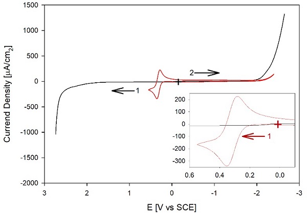
(+) marks the starting point of the LSVs, while the arrows indicate the initial direction of each scan-all other conditions as in Fig. 1. The inset shows the region of interest for Fc, starting at (+, red) and scanning initially in the anodic direction.
Fig. 5. ( , black): LSVs of 0.1 mM TBAP in distilled acetonitrile and after purifying solvent and salt with our optimized procedure. The anodic and cathodic segments were collected from independent experiments starting with a recently polished electrode in blank 0.1 M TBAP. ( , red) CV of a 1 mM Fc in 0.1 M TBAP.
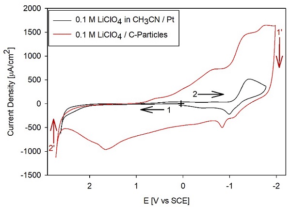
A final test was performed to illustrate the use of the anhydrous CH3CN in an experiment involving the intercalation of Li. Fig. 6 compares the CVs for a freshly polished Pt electrode in an electrolyte prepared with 0.1 M LiClO4 with the results of a C-modified Pt electrode. The solution was 0.1 M LiClO4 without any additional electrolyte, and the CV on C/Pt was obtained once the current became stable after repeating several CVs in the same potential window. The C was obtained from candle soot, a currently investigated source, because it can become a widely available source of relatively simple-to-synthesize materials with potential applications in energy storage. [16-20] The voltammograms show that at potentials positive of -1 V (e.g., from +1 to -1 V vs. SCE in the cathodic segment) SCE, the carbon material (---, red) shows peaks not present in the control for the bare Pt electrode. Note that the currents on the C material are significantly higher than those for the CH3CN background for Pt in the region between 0 and 2.5 V vs. SCE for the anodic processes and between 0 and -1 V for the cathodic side of the CVs. For potentials more negative than -1 V vs. SCE, the Pt and C/Pt electrodes display clear cathodic processes. Because in this region, the background current for 0.1 M TBAP is << 500 (A/cm2, the cathodic process is assigned to the bulk electrodeposition of Li, reaction (7). In contrast, the anodic currents are assigned to the bulk electrodeposition of Li, reaction (7), and the anodic currents are assigned to the reverse of reaction (7):
Note that the Li deposition current is more prominent on the C-modified electrode due to the porous electrode's significantly larger surface area compared to a polished Pt surface. Therefore, because of the low background currents on the solvent, we can assign the processes between 0 and 1 V to the intercalation of Li into the carbon material, similar to the intercalation into graphite, reaction (8): [21]
Conversely, for the anodic currents at potentials more positive than 0 V, the peaks are assigned to the de-intercalation of Li+ or the reverse of reaction (8). These assignments are consistent with prior reports. [18,19]
Conclusions
In summary, we present an approach to optimize the purification of acetonitrile and the TBAP electrolyte for experiments in nonaqueous media. We could not use a single method that did not include distillation because we could not remove water to a concentration low enough with the common drying agents of Al2O3 and molecular sieves 3A. Therefore, we used 3A molecular sieves as a static desiccant, distillation from CaH2, and added Al2O3 to obtain a pure solvent while minimizing distillation steps. The optimized procedure yields a solvent with small background currents, desirable for electrochemical measurements with high signal-to-noise ratios over a wide potential range (ca. 4.5 eV). In addition, as discussed above, smaller background currents result from smaller impurities concentration, which minimizes the chances of chemical complications in CV.
Other methods can provide lower background currents. For example, the procedure of Walter and Ramay [7] yields a solvent with lower background currents; however, this procedure involves four different reflux and distillation steps: from AlCl3, KMnO4, KHSO4, and CaH2. Therefore, our method constitutes a trade-off because it yields a useful solvent over a wide potential window while minimizing laborious steps.
The approach presented here illustrates the different complications in purifying other nonaqueous electrolytes. We use CV theory, signal-to-noise criteria, and voltammetry experiments to guide the purification steps. This experimental design includes discriminating between impurities in the solvent and electrolyte salt. The approach and theoretical guidelines are generally applicable to other nonaqueous electrolytes.


 nueva página del texto (beta)

