1. Introduction
Nowadays, the use of fibers in concrete has become a frequent trend in the construction industry. In our country, they initially replaced steel wire meshes in shotcrete, industrial floors, and precast elements. Worldwide, the application of this technology varies from pavements, industrial floors, slope support and architectural elements to tunnel construction (Gettu et al., 2004; Kasper et al., 2008; De la Fuente et al., 2012). Currently, steel fibers are also used in precast segments for tunnels lining (Blom, 2002), (Burgers et al., 2007), (De la Fuente et al., 2013). In Mexico, the first work sites, both in civil works and mining.
One of the main benefits provided by fiber reinforced concrete is the energy absorption capacity after cracking, meaning that regardless how much the element cracks, it may keep on withstanding the load and strain without collapsing, allowing tensile strength redistribution (De Waal, 2000), improving fracture behavior, fatigue performance and impact strength (Gopalaratnam y Gettu, 1995). Efficiency of fibers included in the concrete mix depends on (1) the fiber properties, strength, stiffness and bonding, (2) fiber distribution, volume fraction, content and orientation (Zollo, 1997).
Several standardized test methods have been developed to measure energy absorption which allows to assess the fiber reinforced concrete performance. For its application, it is important to keep the following into consideration: 1) Test complexity; 2) Difficulty to prepare the samples; 3) Execution complexity; 4) Test replication; 5) Cost and applicability in real life, as well as acceptance of the test method by researchers (Kooiman, 2000). Methods proposed to evaluate FRC should be assessed according to the above-mentioned conditions to determine its practical application as Protocols in the Work Control for FRC.
Having in mind the above premises and the vast experience of Instituto de Ingeniería de la UNAM [UNAM Institute of Engineering] in research on FRC, this paper submits the results of an experimental program to evaluate SFRS in a practical case, extension of Mexico city metro line 12 (L-12). Energy absorption (toughness) of primary lining fiber reinforced shotcrete of L-12 tunnel and the complexity to prepare samples for square panel test EN 14488-5 (l 600 × l 600 × h 100 mm), round panel test ASTM C1550 (ϕ 800 × e 75 mm) and Barcelona test UNE 83515 (h 150 × ϕ 150 mm) are evaluated. It was decided to use the international standards because during this experimental campaign, we did not have standards allowing to evaluate this type of tests in Mexico.
2. The line 12 extension subway tunnel
2.1 Overview
Mexico City Projects and Services Secretary builds the extension of Mexico City metro line 12. It is an infrastructure project consisting of a 4.6-kilometer-long tunnel where three metro stations will be located, connecting Mixcoac and Observatorio stations, and connecting the East and West areas of Mexico City. With this Mexico City metro line 12 extension, it is estimated that the commute between Mixcoac to Observatorio Stations will be up to 60 per cent faster.
The executive project which is currently in its first stage consists of building 13 shafts between 15 and 46.5 m deep. Along the project the stratigraphic profile of the soil consists mainly of tough sandy clay, however, in some sections of the tunnel, there are soft soils with poor stability. There is no groundwater level. Where unstable soils were found, it is solved it with supporting elements, such as metal frames with 0.50 m to 1.00 m separation between them, depending on the type of soft soil. In other cases, with overexcavation, it was solved with injection products, such as cement slurry and fluid concrete, chosen according to the overexcavation size.
To build the 4.6 km long and 11 m average diameter tunnel, a conventional mechanic excavation method using roadheader tunneling equipment. To excavate the tunnel face, the roadheader is moved towards the face and the cutting head is set in motion. The face of the tunnel is then milled off in sections with the cutting head. The average digging progress is of 1.5 m, with an average of two to three per day. After digging the top middle section, primary lining is placed to stabilize the land. This consists of applying steel fiber reinforced shotcrete (SFRS). The primary lining width is of 20 cm, placed in approximately two 10 cm layers each one. Between the primary and secondary lining, a PVC geomembrane is placed to prevent water leaks towards the final lining. The secondary lining is made of 40 cm width concrete in the vault. In this second lining layer, conventional shotcrete with no fibers is used, reinforced with rebars.
2.2 Control tests
The most representative property of SFRS is energy absorption. After concrete cracks, fibers start working during the cracking process, redistributing and controlling cracks spread as the SFRS lining system strains. SFRS load capacity determines the lining system performance.
SFRS energy absorption is determined by means of flexure tests. There are two traditionally used procedures: a) the panel test, round or square section, and b) the beam test. New globally used, standardized test methods have been developed to determine this. The beam test is mainly used in pavement applications.
The post-elastic performance of round/square panels subject to a point load in the center, is represented by the energy absorbed up to a specified central deflection. The typical flexure strength test methods include ASTM C1550, round panel and in EN 14488-5 square panel. The energy absorption capacity determination is the most important factor to evaluate the SFRS performance, calculated for a specified deflection, 25 mm in square panel and 40 mm in round panel. Other methods to evaluate flexure strength are the beam tests. To perform this test, SFRS panels cut in beams are required, and they are tested according to the ASTM C1609 and UNE EN-14651 standards, to determine the flexure toughness.
A recent development is the double punching test (DPT) proposed by Chen (1970) standardized by UNE 83515, known as the Barcelona test. With this test, the cylinders’ toughness is determined, calculated for a 6 mm specified circumferential opening. Carmona et al., (2009), deems this test is characterized by its low complexity in test specimens’ preparation, it provides a suitable FRC systematic control in the work site and poses a great specific crack surface along its height.
To evaluate the primary lining concrete performance of L-12 tunnel, II-UNAM carried out control tests, manufacturing different types of SRFS specimens obtained in the tunnel, and it launched an experimental campaign following up all concrete placement operations, emphasizing in the specimens sampling and tests.
Figure 1 shows a typical procedure of SFRS primary lining placement in L-12 tunnel. Upon arrival to the work site the concrete truck obtains a concrete sample, it measures temperature and slump for purposes of either rejecting or accepting it. In case it is accepted, the design fiber quantity is immediately included, allowing it to integrate and mix during the stated time. Once the mixing time is over, the concrete is supplied inside the tunnel by means of a pipe, received by a mixer truck that takes concrete from the shaft to the front part of the work site, adding it to the shotcrete equipment. Materials used for concrete production were: cement CPC 40RS (NMX-C-414-ONNCCE), stone aggregates: andesitic sand, 10 mm maximum limestone gravel (NMX-C-111-ONNCCE), type B and F admixture (ASTM C 494), accelerating admixture TamShot 70 AF (ASTM C 1141) and 35 mm long steel fiber, slenderness ratio (l/Ø) 65, tensile strength of 1.345 (N/mm2), in a dose of 30 kg/m3 of concrete. 0.50 water/cement ratio. Design compressive strength specified at 28 days is of f´c = 250 kg/cm2.
Three types of sampling were carried out, round panel, square panel, and blocks, with which the following tests were performed: ASTM C1550 (round panel), EN 14488-5 (square panel) and UNE 83515 (Barcelona test). All test specimens obtained for this experimental campaign belong to the same mix design and each type of sampling belongs to the same batch supplied in field. Notwithstanding, the mix design information is not available because it is owned by the concrete supplier.
3. Square panel test - en 14488-5
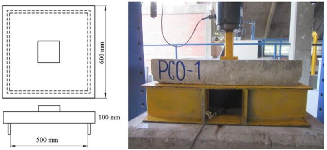
Square panels, of 600 × 600 ×100 mm, were subject to a central load applied through a 100 × 100 mm and 20 mm thickness square plate, according to EN 14488-5. The load and the axial displacement of the jack are registered during the test. The behavior is evaluated through the maximum load and the energy absorption for a displacement of 25 mm. The energy absorption is calculated as the area enclosed by the load‐displacement curve up to the specified displacement.
The test was carried out in a rigid load frame with a capacity of 500 kN and with a closed‐loop control system. The displacement rate was 1 mm/min and a LVDT transducer was located at the center of the panel to measure the displacement.
Figure 2 shows the setup of the square panel test according to EN 14488-5. The rough side shall be on the top during the test, i.e. the load is applied on the spraying direction.
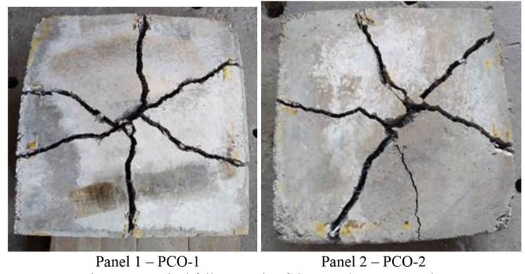
The experiment test series was performed on 3 square panels, identified as PCO-1, PCO-2 and PCO-3. The specimens were obtained from the same concrete batching supplied in the primary tunnel lining. Cracks were generated in a classic pattern from the panel centers, producing multiple fragments as shown in Figure 3. In all cases, two main cracks and others secondary are observed in each panel, going from the center to the sides of the panels. The failure was gradual due to the fibers action in the concrete matrix.
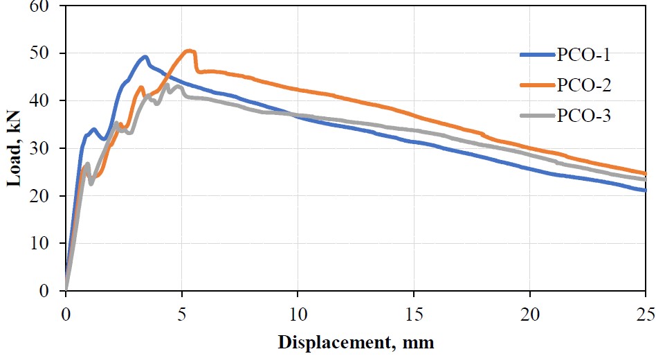
Figure 4 shows the load-displacement curves of the tested panels. The curves show a similar behavior, regardless the tested panel. Two stages can be identified: the ascendant initial and the descendant post-crack. In the former stage, the load gradually increases at a low displacement rate, and various peaks are reported. At this stage, the fiber contribution is very low. Once the crack appears, the fibers start working together with the concrete. The peaks reflect the descending load descends mainly due to the concrete cracking and the respective recovery due to the initial fiber contribution, until a maximum load value is reached. Then the second stage starts as a progressive descendent post-crack curve, reproducing the fiber main contribution. The test ends at a 25 mm deflection. Figure 4 shows that post-cracking behavior is very similar for the tested panels, likewise, maximum load values are very much alike; therefore, it is estimated that energy absorption will show similar values.
Toughness was determined as the area under the load-displacement curve between the origin and the 25 mm central displacement, as specified in EN 14488-5. Results are shown in Table 1. The results show that average toughness (energy absorption) of the tested panels is of 843.14, with a 5.27% variation coefficient. The repetitiveness of the results is quite acceptable.
Table 1 Toughness results, Tδ25mm
| ID | Panel | U | Toughness | Average |
|---|---|---|---|---|
| T d25 mm | PCO-1 | Joules | 820.83 | Tprom = 843.14 J |
| T d25 mm | PCO-2 | Joules | 894.29 | C.V. = 5.27% |
| T d25 mm | PCO-3 | Joules | 814.31 |
These test panels have a high level of complexity in their sampling, transport and testing because the specimens weigh in average 80 kg each one, in addition to requiring at least, two trained people to prepare and handle the samples during the sampling and testing. For its preparation, additional amount of concrete mix for sampling should be taken into consideration, approximately 0.1 m3 for the three test specimens, which represents an additional cost in concrete. This one will be affected by the test frequency, however, it will be applied if the project specifies its use in the Control Protocol as the evaluation method, or alternatively, use another test in case its correlation with this one is known.
4. Round panel test - astm c1550
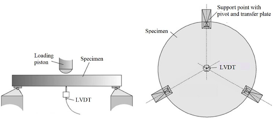
The test was performed on the specified round panels, 75 × φ 800 mm, in accordance with the standard ASTM C1550. In Mexico, the standard test method equivalent to ASTM C 1550 is NMX C539 (NMX 539, 2017). This test method covers the determination of flexural toughness of fiber-reinforced concrete expressed as energy absorption in the post-crack range using a round panel supported on three symmetrically arranged pivots and subject to a central point load. The fixture supporting the panel during testing shall consist of any configuration that includes three symmetrically arranged pivot points on a 750 mm diameter pitch circle. The supports shall be capable of supporting a load of up to 100 kN vertically applied on the center of the specimen. The supports shall be sufficiently rigid so that they do not displace in the radial direction. The pivots shall not restrict rotation of the panel fragments after cracking. Figure 5 shows the round panel test configuration.
The test specimen is mounted in the test apparatus by placing the molded face in the three transfer plates resting on the pivots.
During the test, the load and displacement are continuous, and the load-displacement curve is obtained which will allow to get energy absorption.
The test was carried out with the same equipment used in the square panel test. The displacement rate was 4 mm/min and the test stopped at a displacement of 40 mm. A LVDT transducer with a range of 100 mm was placed at the center to measure displacement. The energy absorption is calculated for displacements of 5, 10, 20 and 40 mm.
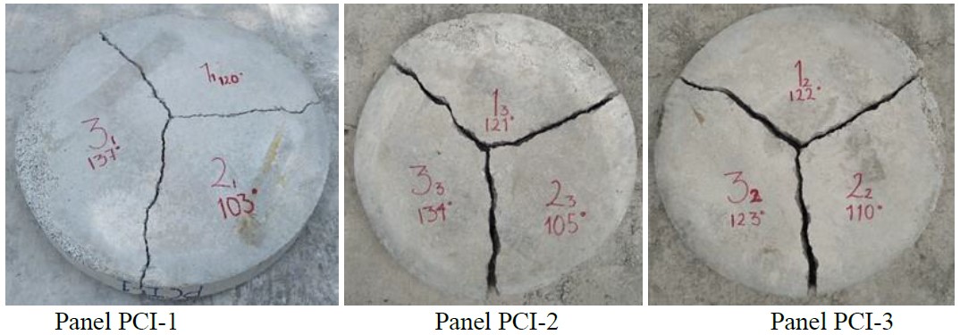
A typical failure mechanism of round panel consisted of three radial fracture planes, as shown in Figure 6. The failure mode was progressive because of fibers in the concrete matrix, unlike the panel tests with no fibers where the failure happens suddenly according to previous experience (Aire and Rodríguez, 2011).
According to ASTM C1550, a sample shall consist of at least two successful tests. A successful test involves a failure that includes at least three radial cracks. Specimens occasionally fail in a beam-like mode involving a single crack across the specimen that is characterized by low energy absorption. The result of such a test shall be discarded. Only two specimens need be tested if both specimens fail by the required mode. In this paper, the three panels had three radial cracks.
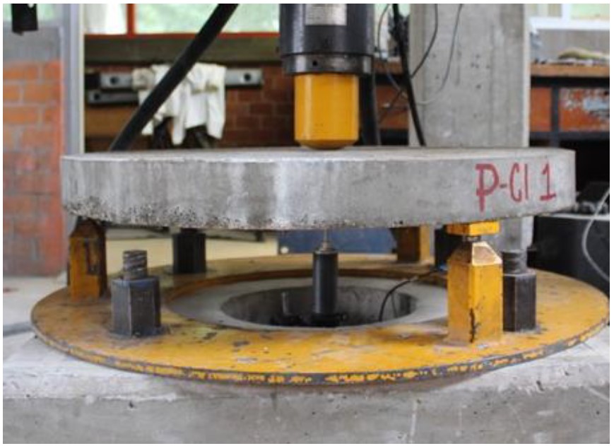
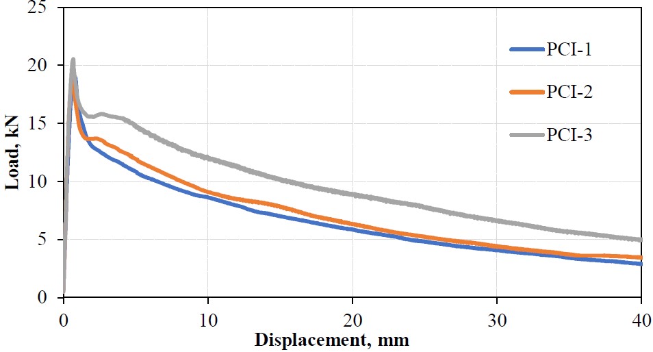
Figure 7 shows the round panel test configuration and Figure 8 shows the load-displacement curves from obtained results. The initial ascendant line represents the load increase at small displacement increments, mostly taken by the concrete matrix. At that part of the test, the fibers contribution is minimal or null. In this stage, the curve reaches a maximum peak (maximum load) to proceed to the concrete cracking stage when the load is taken by the fibers, which work together with the concrete. Loss of load is observed when the concrete cracks; however, a load recovery follows as a result of the fibers contribution and its perfect anchorage with the concrete. The displacement increases (deflection) while the load lowers progressively. This unload stage is mainly due to the gradual fibers anchorage loss, which produces the fibers slip followed by the final concrete rupture.
Energy absorption (toughness) was determined as the area under the load-displacement curve between the origin and the central displacement specified in ASTM C1550. Results are shown in Table 2. Average energy absorption for tested panels is of 311 Joules for 40 mm displacement, with 19.7% variation coefficient.
Table 2 Toughness results, Tδ5mm, Tδ10mm, Tδ20mm y Tδ40mm
| ID | U | T d5 mm | T d10 mm | T d20 mm | T d40 mm |
|---|---|---|---|---|---|
| PCI-1 | Joules | 63.8 | 111.6 | 182.4 | 265.6 |
| PCI-2 | Joules | 66.7 | 118.8 | 196.0 | 286.9 |
| PCI-3 | Joules | 77.2 | 143.3 | 246.1 | 380.8 |
| Taverage | Joules | 69.2 | 124.5 | 208.2 | 311.1 |
| CV | % | 10.2 | 13.3 | 16.1 | 19.7 |
Like square panels, round panels pose handling difficulties, because they weigh approximately 100 kg., each one, in addition to sampling, transport and testing. For round panel, an additional 0.15 m3 volume of concrete is necessary to prepare the test specimens. In both cases, round and square panels pose difficulties in the curing process, especially because they require more space in the curing room. By the same token, as in the case of square panels, if the specification requires it, it will be necessary to carry out sampling and testing.
5. Barcelona test- une 83515
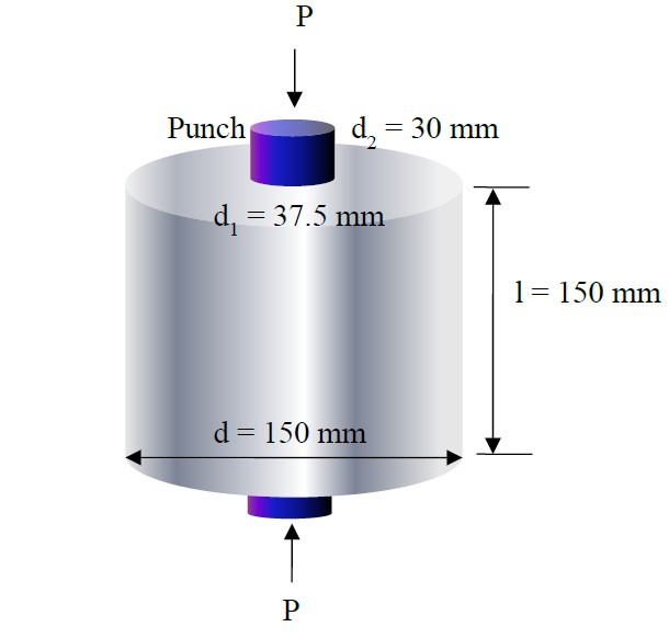
Barcelona test was performed according to the Spanish Standard UNE 83515 on cylindrical specimens, 150 × φ 150 mm. In Mexico, the standard test method equivalent to UNE 83515 is NMX C538 (NMX 538, 2017). This test method is used to determine the cracking strength, ductility and residual tensile strength of fiber reinforced concrete. It is based on a double punching test of a cylindrical test specimen. The essential elements to apply this test method are the circumferential extensometer, steel punches that will act as load elements and mounting disks. The test specimen is a cylinder with height approximately equal to its diameter. The standard diameter of the specimen is 150 mm. This cylinder can be obtained by direct moulding of a 150 mm diameter by 150 mm height specimen, or direct moulding of a 150 mm diameter by 300 mm height specimen, followed by cutting at the midpoint of the specimen height in a plane perpendicular to its axis of symmetry or 150 mm diameter by 150 mm height specimen extracted from a real structure, which represents an advantage of this method when casted in place concrete performance needs to be evaluated. Figure 9 shows a diagram of Barcelona test configuration.
The load is uniformly applied at a press-piston descending velocity of 0.5 ± 0.05 mm/min throughout the entire test. The test is considered to be complete once the circumferential displacement has reached 6 mm.
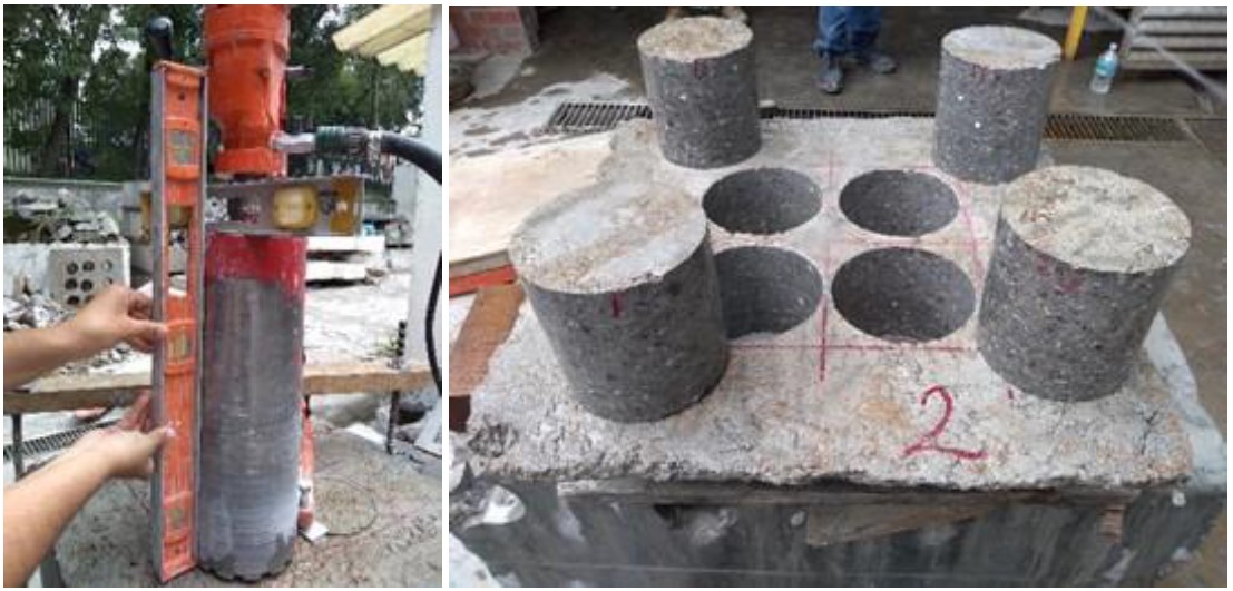
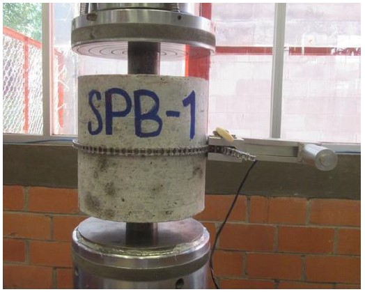
To perform this test, 650 B x 350 b x 150 h mm concrete blocks were sampled, from which 4 cylindrical cores were extracted. Figure 10 shows the equipment used to extract the samples. The specimens’ vertical position was ensured leveling the support surface. The load was applied on the spraying direction. Figure 11 shows the test configuration.
A typical failure mechanism consists of three radial fracture planes, as shown in Figure 12.
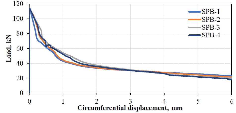
The load-circumferential displacement curves of the tested cylinders are shown in Figure 13. The curves have an almost null displacement from the beginning of the load application to the maximum load. At this stage, the cylinder does not develop cracks. When the maximum load is reached, the first cracks start to appear. At the post-crack stage, the load decreases up to a determined circumferential opening, when the structural fibers start their work. The load is then recovered, and a residual behavior is observed.
Table 3 shows the toughness results of tested cylinders. The results variation coefficient varies between 2.5% and 6.8%.
Table 3 Toughness results, Tδ2mm, T2.5mm, Tδ4mm y Tδ6mm
| ID | U | SPB-1 | SPB -2 | SPB -3 | SPB -4 | Average | CV % |
|---|---|---|---|---|---|---|---|
| Tct 2 mm | Joules | 102.9 | 108.9 | 120.2 | 115.5 | 111.9 | 6.8 |
| Tct2.5mm | Joules | 119.2 | 125.5 | 137.9 | 132.5 | 128.8 | 6.3 |
| Tct 4 mm | Joules | 163.8 | 170.2 | 182.8 | 177.2 | 173.5 | 4.8 |
| Tct 6 mm | Joules | 214.7 | 219.1 | 227.9 | 220.5 | 220.5 | 2.5 |
The UNE 83515 also has the advantage of low weight (5 kg) and volume specimens, casted in cylinders which can be easily handled, and is a more sustainable method. The lower press machine capacity required to carry out the test and the feasibility to core from squared panels for quality control and from an existing structure for post-placement verifications. Additionally, the concrete specimens require a small concrete volume and can be easily handled, which provides a more sustainable method.
6. Conclusions
From results obtained for the three proposed tests regarding energy absorption, the statistical analysis showed more variability in the round panels results and low variability in cylinders for the Barcelona Test. This situation results from the fact that the higher the width, the greater fiber concentration in the concrete core.
Samplings developed so far in the L12 extension work represent a pilot project to assess the methods application, which are not specified for the project, therefore, it cannot be confirmed that obtained values comply with the specified parameters regarding SFRS energy absorption, however, it is a turning point for the implementation of a Control Protocol that evaluates the SRFS performance and allows to know the different scenarios, advantages, difficulties and other things that happen in the work site during the sampling development, resulting from tests and analysis of all involved components.
Derived from the experimental campaign applied to the practical case of Mexico City Metro Line 12 Extension, sampling processes, specimens preparation and Barcelona Test (UNE 83515) are more practical from the viewpoint of the work site conditions, because we are dealing with lower weight and smaller test specimens, compared to panels, therefore, less time is needed to prepare them and when the staff is highly skilled, handling, preparation and tests can be done by only one person.
Increase in the use of FRC, experience obtained from field works and related research has encouraged private sector, construction companies and academic institutions such as Instituto de Ingeniería de la UNAM to bring up, propose and develop national test methods to evaluate FRC, based on international standards, using information in local applications. This will encourage a new quality control system for fiber reinforced concrete in Mexican underground works.


 texto en


