1. Introduction
Structural Health Monitoring (SHM), based on sensor technology has been accepted as an important method for safety assessments of structures in engineering. In SHM, the responses of a structure are traditionally measured using various technologies such as accelerometers (Arias and De la Colina, 2018), distributed fiber optic sensors (Bao and Chen, 2012), Laser Displacement Sensors (LDS) (Song et. al., 2006; Park et. al., 2013), Global Positioning System (GPS) (Tamura et. al., 2002; Breuer et. al., 2002) Linear Variable Displacement Transducers (LVDT) (Arias and De la Colina, 2018), wireless sensors (Li et. al., 2019; Guo et. al., 2014; Zrelli and Ezzedine, 2017), and Wheatstone bridge circuit (Li and Hao, 2016). Likewise, several data processing and evaluation techniques such as deep learning (Li et. al., 2019; Guo et. al., 2014), Particle Swarm Optimization (PSO) (Chatterjee et. al., 2017; Moosazade et. al., 2019), and genetic algorithms (Ghasemi et. al., 2018) have been employed for this purpose. Finally, the data is transferred to a monitoring server for analysis of the recorded historical information and evaluation by specialists in the area. The characteristics of the structure and the various loads (wind load, seismic load, and service load) determine the target structural elements, the types of response and the required measurement sensors. Therefore, the selection of a response index that can accurately assess damage to a structure is critical.
For the development of microelectronics applications, the design methodology of Application-Specific Integrated Circuits (ASICs) is used, which presents several development alternatives (Maxinez and Alcalá, 2007). Programmable logic is a type of design that uses Programmable Logic Devices (PLDs), such as Field Programmable Gate Arrays (FPGAs), which can be characterized from the outside through various programming techniques using a Hardware Description Language (HDL).
The objective of this work is to provide a proposal for the development of an electronic system that can determine the stability of a multi-story building based on the evaluation of the relative displacement measurement of the mezzanine that is obtained by a network of ultrasonic sensors that acquire measurements directly from the vertical structural elements in a non-invasive manner.
2. Methodological development
In this section we present the development of our proposal, first we present the specifications and scenarios, then we start with the modeling of the proposal, continuing with the approach of the solution algorithms and their programming, ending with the implementation of the system.
2.1 Specifications and scenarios
The most important parameter for determining the magnitude of possible damage to buildings is the mezzanine distortion γ, that is, which is the relative displacement of the mezzanine ∆, divided by the mezzanine height H.
In equation (1) it can be observed that the mezzanine distortion is a dimensionless parameter, since both ∆ and H have length dimensions, and it can be used in percentage terms. To evaluate we based on what was established by Pauly, (2001), which proposes that the measure of permissible average displacement will lay between 2.0 and 2.5 % of H, from this premise the system inference engine table will be built and from this the system will react in a predetermined way to activate the actuators.
The practical case is not a general case, it is specifically proposed for a structure with a well-defined rectangular geometry, for which the model of a six-level structure with a heigh of each mezzanine Hi =3.5 m is used, with flexible vertices each level for the generation of inclinations. The purpose of the model used is solely to collect measurements to obtain the relative displacement of the mezzanine and the stresses analyzed are of one-dimensional nature, since, if they were otherwise, a general geometry would have to be analyzed with stresses of a vertical nature that they can cause displacements in more than one direction, induce rotations, transverse modes of vibration, longitudinal, torsional, etc. Therefore, it is important to mention that the analysis is bounded to the one-dimensional stress in the vibration-free rectangular structure
To obtain the value of the lower limit state of the proposed case, we use equation (1) and formulate it as follows:
We must consider that 2.0 % of Hi is 0.07m. For the case we pose:
To obtain the maximum permissible average displacement of the complete structure, the average displacement multiplied by the number of levels is used, in this case the relative displacement of the mezzanine lower limit is obtained:
In the same way to obtain the value of the upper limit state, we must consider that 2.5 % of Hi is 0.0875m. And we obtain:
2.2 Modeling
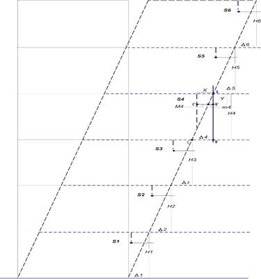
In a first stage, to obtain the measurement of the relative displacement of the mezzanine of a six-level model structure, it is proposed to develop the Sensor System of Ultrasonic Relative Displacement in Pendulum (SSURDP) block, in which the relative displacement measurement of the mezzanine is calculated, for this, a system was designed that integrates a net of high-capacity ultrasonic sensors HC-SR04 placed suspended on the mezzanine ceiling to obtain the measurement of the relative displacement at specific points of a building, the sensors are the elements capable of obtaining the parameter of a physical signal that is conditioned into a convenient signal for its interpretation, and thus integrate these into a data acquisition system to adapt the signals obtained in data that we can process in the analysis stage. Figure 1 shows the parameters to consider: measurement obtained by the sensor M i, measurement of the base of the similar triangle that is generated in the triangle on the right-side m i, relative displacement of the mezzanine ∆ i and the height of the mezzanine H i , which is known. When the structure suffers an inclination, the sensors for M i due to the effect of gravity will remain in the original vertical axis, the mezzanine wall follow the inclination of the mezzanine, with which, when projecting the inclination we must consider that the references of the coordinate axes are translated and the projection describes two triangles, we can identify that both triangles contain two similar triangles that would comply with Thales’s first theorem, then, applying the similarity relations for similar triangles we can obtain the value of the bases, noting that the base of the triangle on the right side, as we represent it in the diagram, we identify it as the relative displacement of the mezzanine ∆ i . The measurement M i obtained by each sensor varies, undergoing a decrease that will be used so, through the similarity relation applicable to the case, the length of the base of the triangle on the right could be obtained, which, as indicated, corresponds to the relative displacement of the mezzanine ∆i. With these data, the distortion of the mezzanine from each level is calculated and it is determined which of the measurements is the largest to enter the limit state evaluation.
As explained above, we can base ourselves on Thales’s first theorem and stablish a relationship for similar triangles:
Identifying the elements, we have that:
The measurement AB = H
The measurement B´C´= m
The measurement m = X - M
The measurement BC = ∆
Then, from equation (6) we take:
Substituting we get:
We solve for ∆ and obtain the expression:
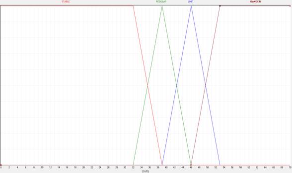
In a second stage, the value of the relative displacement measurement of the mezzanine is received, whose magnitude is the largest of the six that were determined, this parameter will be the input variable to a Rule-Based System (RBS), the analysis will be based on the principles of fuzzy logic for which we first assign a universe of discourse in the desired range, in this case from 0cm to 70cm, where 0cm represents the initial and calibrated state of the perpendicular of the building and its base, and 70cm we consider a sufficiently permissible value since from the calculations obtained in (4) and (5) the limit state for the case is between 42.0cm and 52.5cm, with which we determine to set the limits between 39.0cm and 53.0cm, which means that a measurement greater than 53.0cm would represent that the structure would be in danger of collapsing, for which reason the range that we propose is more than enough to allow the inference system to work in a mayor range to the established limits and not act immediately if these measures are exceeded.
With this consideration, we determined to use four membership functions: two trapezoids and two triangular ones, to give meaning to each linguistic variable. Each membership function identifies the range of input values that correspond to a linguistic variable, the membership functions map to the present data to determine the degree of membership. That is, the physical values of the input variable, that is the largest of the measurements obtained by the sensors, are converted into linguistic values.
In Table 1 we show the ranges how the input variable is partitioned, these ranges were defined subjectively with the support of an expert, who adjusted these ranges so that the behavior of the input measure will observe the correct assignment of membership to the function in which it obtained the greatest value.
Table 1 Ranges of the input variable DESP_REL.
| Set | Range (cm) |
|---|---|
| STABLE | 0 - 39 |
| REGULAR | 32 - 46 |
| LIMIT | 39 - 53 |
| DANGER | 46 - 70 |
We apply what we have determined and feed the fuzzyTECH software using a membership function for each established range, these being two triangular and two trapezoidal. In Figure 2 we can identify the membership functions for the input variable DESP_REL that corresponds to the largest of the relative displacement measures and that are defined with the linguistic terms: STABLE, REGULAR, LIMIT and DANGER. The four membership functions used allow the limit ranges calculated for the practical case not to activate the outputs towards the actuators when reaching a maximum limit; that is, proposing two triangular membership functions for the REGULAR and LIMIT terms allows handling values between 32.0 cm and 53.0 cm to identify the membership value of a physical value of the input variable in order to observe the behavior of this and in this range, a degree of belonging is assigned that corresponds to a linguistic variable that allows us to dose the operation of the actuators in the following phase.
Now we conveniently extract the ranges for each membership function, to describe each of these we use the equation of the point-slope line and obtain:
Third stage: Reasoning. This inference process determines the most appropriate output of the system from two implications, on the one hand, the input data and on the other the knowledge base. Inference is a computation consisting of two main steps: aggregation and conclusion. It will allow us to obtain logical deductions from propositions. Knowledge is presented by rules of the IF-THEN form, the actual behavior of the system is defined by individual rules. To prototype an appropriate set of rules, we started by creating rules that represent unambiguous controller strategies at specific operating points. Once these have been established, we proceeded to the construction of the set of rules, in Table 2 we present the four rules that were established as sufficient to determine the desired behavior of the system, this was done by direct assignment of behavior to actuators that was determined with the help of the expert.
Table 2 Production rules.
| DESP_REL | A_VISUAL | A_ACOUSTIC | A_MESSAGE |
|---|---|---|---|
| STABLE | AVGREEN | TURN OFF | TURN OFF |
| REGULAR | AVYELLOW | TURN OFF | AMCAUTION |
| LIMIT | AVYELLOW | TURN OFF | AMALERT |
| DANGER | AVRED | ALERT | AMALERT |
Fourth stage. At this stage we get the exact value of the output. Then we only need to transform the membership values provided by the inference engine, into a real value for practical purposes from the consequents of the rules that have been activated, it is necessary to obtain a single control action combining the result proposed by each one of them.
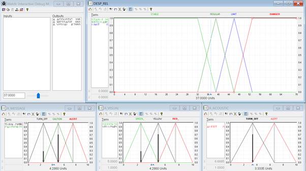
A designed system check is initiated by invoking a debug mode of the fuzzyTECH software. All changes made to the driver are immediately implemented in the current debugged driver task, this allows testing of changes entered into the driver due to specific input data, that is, verifying the behavior of the system with manually entered data. The range from 0 cm to 70 cm is covered completely. Figure 3 shows the case when the input is fed with a value of 37 cm that is manually fed and the value that would correspond to the outputs.
2.3 Proposed algorithm
We propose to proceed as follows:
Inference data type declaration (stable, regular, limit, danger) Process MEMBERSHIP Converts distance (BCD) to dis (integer) Evaluates dis Assigns SlopeNegative and SlopePositive Assigns MembershipNegative and MembershipPositive End Evaluates End MEMBERSHIP Process REASON Declaration of process variables while SlopeNegative and SlopePositive result = SlopePositive and belongs = MembershipPositive if not, result = SlopeNegative and belongs = MembershipNegative End While End REASON Process OUTPUT If rising edge Evaluates belongs Assigns values to outputs End Evaluates End OUTPUT
RBS algorithm for SSURDP.
2.4 Implementation
Once the system has been debugged, verified and optimized we can program the necessary modules to implement the Rule-Based System for the Sensor System of Ultrasonic Relative Displacement in Pendulum (RBS for SSURDP).
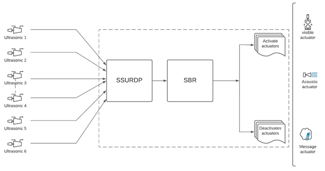
Then SBR for SSDRUP embedes the inference engine that is responsible for evaluating all the measurements collected by the sensors, determines the largest of the measurements, evaluates and establishes the state of structural health that is determined with the inference rules, and generates the logical levels of the system outputs to activate or not the operation of the intended actuators. Finally, Figure 4 shows the SBR system for full SSDRUP.
3. Materials and methods
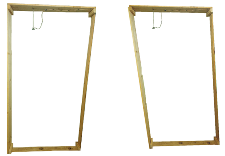
A wooden model was employed with flexible vertices to generate the inclinations manual and independently for each level. Instrumented with a system of six ultrasonic sensors HC-SR04, each one set on every level suspended at 45cm from the roof of the mezzanine, and at 50cm from the limit wall located in the entrance of the lateral force. The purpose of suspending the sensor in the roof of the level to analyze is to generate the pendulum effect when the inclination is produced, see Figure 5. The system just requires a simple calibration regarding the vertical axis reference. The sensor did not rotate during the measurement, the pendulum approximation is for small oscillations, the subtended angle between ultrasonic transmitter, the contact point of the structure and the echo receptor is almost zero. The sensor preserved all the time the vertical orientation during the measurement, such that the structure kept oscillating, but using the pendulum, there may be phase changes that alter the measurements.
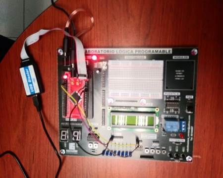
For the modeling and verification phases the software fuzzyTECH 6.03 IA-S7 was employed, it provides a graphic definition of the membership functions of each term employed and eases the debugging of the system designed. The system was implemented using methodology for the hierarchical design and integration entities of the logic programable, and its programming in the hardware description language VHDL in the platform Intel Quartus II V.13.0.1 Web Edition. RBS for SSURDP was embedded in a FPGA EP2C5T144C8, see Figure 6, the conditioning of the output signals toward the actuators, have visual indicators of the current logic levels.
4. Experiments and results
In order to validate the system proposed, the described model was implemented, and a test set was designed where in every experiment, each one of the six levels of the model are manipulated independently, such that different inclinations are generated in each one of them. SSURDP obtains the relative displacement measurements of each mezzanine y determines the largest value of these measurement, which RBS for SSURDP uses for the evaluation.
Test 1. SSURDP determined 21cm as the largest of the six measurements, so, RBS for SSURDP assigns the membership of the input variable the linguistic value STABLE and sets the logic levels for the outputs of the actuators, see Figure 7.
Test 2. SSURDP determined 37cm as the largest of the six measurements, so, RBS for SSURDP assigns the membership of the input variable the linguistic value REGULAR and sets the logic levels for the outputs of the actuators, see Figure 8.
Test 3. SSURDP determined 41cm as the largest of the six measurements, so, RBS for SSURDP assigns the membership of the input variable the linguistic value REGULAR and sets the logic levels for the outputs of the actuators, see Figure 9.
Test 4. SSURDP determined 44cm as the largest of the six measurements, so, RBS for SSURDP assigns the membership of the input variable the linguistic value LIMIT and sets the logic levels for the outputs of the actuators, as shown in Figure 10.
Test 5. SSURDP determined 49cm as the largest of the six measurements, so, RBS for SSURDP assigns the membership of the input variable the linguistic value LIMIT and sets the logic levels for the outputs of the actuators, see Figure 11.
Test 6. SSURDP determined 50cm as the largest of the six measurements, so, RBS for SSURDP assigns the membership of the input variable the linguistic value DANGER and sets the logic levels for the outputs of the actuators, see Figure 12.
The logic values from the outputs to the actuators are verified physically in the visual indicators of the conditioned outputs, they are reported in Table 3.
Table 3 Logic values from the outputs to the actuators.
| Test | Δ(cm) | Membership | SAAalert | SAV green | SAV yellow | SAV red | SAM caution | SAM alert |
|---|---|---|---|---|---|---|---|---|
| 1 | 21 | STABLE | 0 | 1 | 0 | 0 | 0 | 0 |
| 2 | 37 | REGULAR | 0 | 0 | 1 | 0 | 1 | 0 |
| 3 | 41 | REGULAR | 0 | 0 | 1 | 0 | 1 | 0 |
| 4 | 44 | LIMIT | 0 | 0 | 1 | 0 | 0 | 1 |
| 5 | 49 | LIMIT | 0 | 0 | 1 | 0 | 0 | 1 |
| 6 | 50 | DANGER | 1 | 0 | 0 | 1 | 0 | 1 |
Test 1: The system determines that the 21cm of relative displacement belongs to the STABLE category; hence, the output towards the green visual actuator is activated, and the other actuators are turned off, indicating that the structure is stable and without collapse risk.
Tests 2 and 3: the measurements obtained, 37cm and 41cm, respectively, the system determines the status as REGULAR, the yellow visual actuator and the caution message actuator are turned on; the other actuators are turned off; This provides a visual and message alert that the structure is in a compromised situation.
Tests 4 and 5: There are obtained measurements of 44cm and 49cm, respectively, the system stablishes the LIMIT status; thereby, the system activates the corresponding actuators: the yellow visual turned on and the alert message actuator are turned on, and the other actuators are turned off, this alerts that the structure is compromised and at risk of collapse.
Test 6: The measurement obtained is 50cm, therefore, the system establishes the DANGER status and activates the three corresponding actuators to alert of the situation: the acoustic actuator, the red visual actuator, and the alert message actuator are turned on, while the other actuators are turned off; in this case the structure considered seriously damaged and in risk to collapse.
The lower limit computed in (4) is 42cm; hence, a larger relative displacement measure would activate the alerts and a lower measure would not activate them. In test 2 with a measure of 37cm, thus, the warning alerts are turned on; hence, the system doesn´t expect the lower limit to react. Also, for the upper limit computed in (5), is 52.5cm, so, it would expect that from this relative displacement measure, the structure is unstable. In test 6 there is obtained a measure of 50cm, that is, a lower measure to the upper limit of the system, the status is set as DANGER, the three corresponding actuators alert about the situation. Thereby, the system is validated because it reacts in a dosed manner, not only to maximum and minimum values, according to the design performed.
5. Discussion
Monitoring the structural health uses, mainly, displacement laser sensors and accelerometers, representing a high cost and technical complexity for their management; also, often there are required fixed points to perform such measurement.
Li and Hao, (2016) report the development of a relative displacement sensor, that employs the Wheatstone bridge circuit principle, they determine a damage index, where the sensor measures the local relative movement, and it is sensible to the changes of condition locally.
Park et al., (2013) employ a laser displacement sensor and a customized wireless sensor node that measure the displacement as a damage index with which they implement SHM to verify and correct the design parameters of an irregular edification. This method involves to use the optic technique LDS to obtain the distance of the objective by triangulation with its inherent complexity.
Our proposal is based on a Sensor System of Ultrasonic Relative Displacement in Pendulum (SSURDP), that it is capable provide the measure of the mezzanine relative displacement by taking only one measurement, it just requires that the sensors are located, toward the vertical structural element, on the side of the incoming horizontal force that is identified, and the measurement performed taking advantage of the pendulum effect. We follow what Paulay, (2001) who indicates that to evaluate we must consider that the magnitudes of medium displacement should not exceed 2 to 2.5% of the height H and with this we establish the limit of the relative displacement measurement and provide our own damage index for the SHM.
In the three proposals there are developed different relative displacement sensors, and a particular damage index is proposed for each case, thus, it is no possible to establish an efficiency comparison.
6. Conclusions
The proposal for the location of the sensors and the pendulum effect caused by their suspended placement was correct, since the geometric projections generated allowed, based on a measurement of each suspended sensor, through the relationship of similarities that can be applied in this case by contain similar triangles and using the corresponding mathematical mechanisms, the measure of relative displacement of the mezzanine was obtained. The system just requires a simple calibration regarding the vertical reference axis.
The application of the hierarchical design of the programmable logic with programming VHDL, allowed the design of an electronic device capable to obtain measures recollected by the sensor network, to be processed by the SSURDP algorithm, so that to give the mezzanine relative displacement measures, and also to identify the largest magnitude where the RBS algorithm for SSURDP performs the evaluation to evaluate the stability of the structure by the proposed index presented in this study.
The instrumentation with RBS for SSURDP of the model employed in this work, provided the data necessary for evaluation. The results section shows that the system was capable to determine, in each case, outputs toward the actuators, and 100% of the tests implemented corresponded with exactitude to the design established and the actions defined by an expert. We conclude that the RBS for SSURDP system is capable to determine the stability of a structure, in a non-invasive manner, in real time, without requiring fixed points to acquire data, and basing on a parameter: mezzanine relative displacement; therefore, the present proposal can be recommended as a support tool to be used in SHM to estimate the damage in multi-story buildings.


 texto en


